I have a glass panel that needs to be rationalised by squaring its edges. I usually do this by drawing the edge profile I require on a surface perpendicular to the edge and using ‘Follow me’ - but I cannot for the life of me work out how to draw a surface perpendicular to an edge that doesn’t lie on a SketchUp axis.
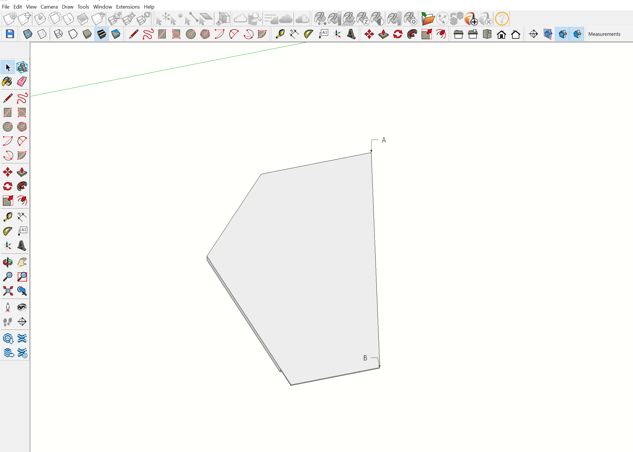
The edge is AB in the following image and a copy of the file in 2021 format is attached. I will upload an earlier file version if that helps?
The Pie tool lets you drag out the axis of rotation, so click and drag on the edge, and you can at least get a surface that’s perpendicular to that edge.
Edit: with the pie tool selected, click on B and drag toward A and that defines the axis of rotation. Then draw any portion of arc and you’ve got a starting surface. You can always draw with the rectangle tool after that by hovering over it, and holding shift to be on that surface.
Not quite Dave - I mean if you extended the line and then looked straight down the line so that it disapeared you would be looking what I call perpendiclar to it. The top edge of the panel would be horizontal if that makes any sense.
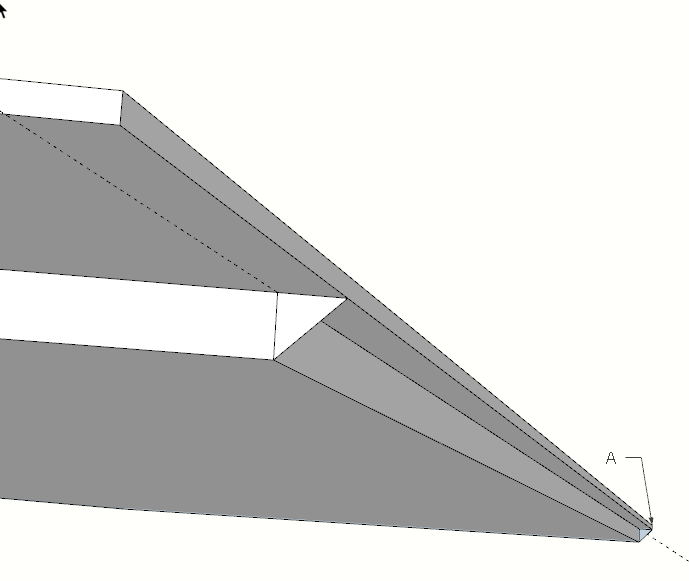
The panel is 40mm thick. Its made of 2 pieces of glass - 10mm & 6mm thick seperated by a 24mm spacer bar. When I look along the line AB I should see this view.
I drew the near “vertical” edge using Inferencing and put in the guideline parallel to the long edge so I could see where it comes out on the opposite end. Then I filled in the rest of the edges and erased the angled face
If I was going to model that panel and starting from scratch I would have drawn the large face, extruded it to the 10mm thickness and then outlined the thicker section and used Push/Pull to extrude to the final thickness. Less screwing around that way.
That’s brilliant Dave! Thank you very much. I didn’t realise you could inference straight off of a plane. I realise now that you can inference anywhere on a plane - not even on an edge. Thanks again.
Should be easy enough to replace the geometry. I opened your group and copied the top face. Then I exited the group and used Paste in place before moving the face straight up in the blue direction. If I was going to replace the panel in the group I would have copied that top face, deleted all of the geometry in the group, pasted in place and then proceeded to add the detail.
Thanks - I will try that. The aim is to come up with glass 2 profiles - one for the outer pane and one for the inner pane so that the panel can be made with no part of the glass being outside of the original profile. So each edge of the panell in section will look something like this.