Greetings ~ I’m using SketchUp 2017 (a marvelous tool). This is a question about using Protractor tool (not Rotate or Orbit tool) to create a guideline that is 32 degrees off of red axis then 85 degrees off of that 32 degree line. Clear as mud? Ultimately, I’m trying to model an angled circular mortise for bench legs.
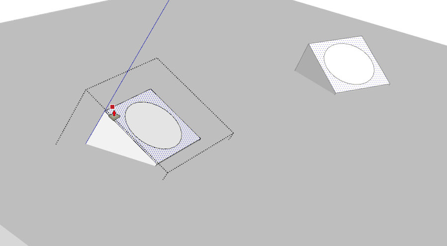
The 32 degree guideline is easy. How do I get Protractor to make a guideline based on that 32 degree line? The attached screenshot shows what I have so far. I selected the 32 degree line to highlight it.
Also, when I search in the SketchUp Help Center for a common Sketchup tool like Protractor why does the search results have nothing about the specific tool? Very frustrating.
It would be interesting to see your model. From your description it feels like you are working too hard to get the mortise modeled. That said, I expect you would find it easier to draw a temporary face along that 32° guideline. Or maybe you could just rotate the 32° guideline to the 85°.
Adding the plane works. My math was wrong ~ it’s a 75 degree guideline.
So, now ~ how to model the circular mortise through the bench? If I add a circle at that intersection, Push/Pull only works on one of the three axis, not a splayed and raked line, correct?
Plus, Push/Pull won’t leave one component and move into another will it?
Push/Pull will let you extend one component through another without affecting the other. You could then use Intersect Faces to get it done. I just realized I have to get to Robotics now but I’ll come back to this when I get home. I expect someone else will have you sorted out by the time I get back, though.
Sorry for the delay. It would be helpful to see more of the dimensions you’re working from. Since I can’t find more, though, this is a bit of a guess as far as the angles. There are sightlines shown in the screen shot. I would set the legs in place centered at where the base line and sightlines intersect and rotate them so their sides are aligned parallel with the sightlines.
Next I would rotate each leg to the splay angle by putting the rotate tool on the side of the leg at the center of the top. I rotated the legs to 32° but that’s probably not the right angle.
You can copy the tenon geometry from the legs and paste in place inside the seat plank. Then use Intersect Faces and erase what isn’t needed.
Easier would be to use the Trim tool in BoolTools2 which will work in Sketchup Make.
I’m not a fan of the way the show the shoulders of the tenons in your screen shot. Maybe they refine them and trim them to the underside of the seat. I would do something to round the legs for a short distance below the shoulders and then counterbore the underside of the seat so there’s a better connection between the seat and legs. Remember the wedges are aligned across the grain of the seat.
You’re quite welcome. FWIW, here are a couple of things to consider for things like this. It can be helpful to think about how you would do this in the shop. Probably you’d mark out the sightlines on the seat. (Use a guideline in SU) and then you’d use that leg angle pattern in your plan or a bevel gauge standing up on the sightline to guide the brace and bit. If it helps, you could draw that pattern in place on the sight line and use it as a reference to rotate the leg.
I find it easiest to model things in place as much as possible and to use what I’ve modeled to help model the next pieces. By using a copy of the tenon geometry to create the mortise, you are guaranteed a perfect fit. Technically it would be a press fit but there’s no friction in SketchUp. Leverage the fact that one object can pass through another. And don’t be stingy with the parts. Let the legs and their tenons run long. They can be trimmed once they are in the right place. And there’s no leftover bits to go into the woodstove.


