Today I found that probably after the last update to 2020.2 I’ve got some strange behaviour with accurate measurements. Does anybody got the same? Look at my gif screen showing that.

measure.skp (96.8 КБ)
Today I found that probably after the last update to 2020.2 I’ve got some strange behaviour with accurate measurements. Does anybody got the same? Look at my gif screen showing that.
I can’t tell what you are having difficulty with from your GIF. Please describe the problem. I’m not having any difficulty putting in dimensions in your model.
It’s a wonder you can do any modeling with that style you have selected.
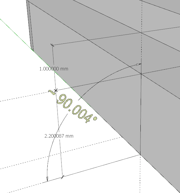
It can be seen on gif that each time I get different results in measuruments. This has never happened before. See that bottom shape has got 2.2 mm height and top is 1 mm height and it placed exactly on the top face of bottom shape. So their all height must be 3.2 mm but tape tool shows height as 3,200058 mm
Looks like you’re creating your problem by having Length Snapping enabled. I turned that off and I have no problem getting the dimensions to add up. You’re model is screwed up in several ways because of the Length Snapping.
I’ve just checked on other models and newly created and there are no problems, everything works as it should. I always use Length Snapping and never get such a problem before. And it can’t be fixed even after exploding geometry or turning LS off.
Using Length Snapping is your choice. It doesn’t take much of search of the forum to find other cases in which Length Snapping has caused similar problems to the ones you show. Most users turn off Length Snapping.
Another problem is the side of the lower shape isn’t square to the ground plane.
Yes, you’re right, don’t know how it could happen while in my style an option to show edges by axes turn on
Length snapping and color by axis are both know to cause issues.
Length snapping tends to make endpoints miss by a small amount.
Color by axis has a rather loose tolerance, certainly far looser than .004.
Having all those decimal places doesn’t guarantee accuracy, especially when working with such small geometry. If this is for 3d printing you would be far better off working in metres and scale down or export with the correct options set to get the size you want.
Didn’t know about that(((
I was trying to tell you that but apparently you didn’t believe me.
why? I believe you)
I have had an issue with solids having sides slightly off axes… It sounds as though using colour by axes may be some of the cause.
So, Dave, am I right that switching off next time only length and angle snapping is not enough for not having same issues? I mean that I also should never use color by axis, while modeling because it could make problems back even if I switched off length and angle snapping options?
Color-by-axis does not cause or create problems per-se, rather it can yield “false-positive” situations where SketchUp shows that an edge is parallel with an axis, when the edge is actually not parallel with an axis. In other words- color-by-axis does not force geometry to be somehow distorted. But it can conceal geometry that the user has somehow themselves caused to be very slightly distorted.
Length snapping, on the other hand, can easily result in or help create distorted geometry. Here is a hypothetical example (I don’t know if this happens as I describe it because I don’t use length-snapping, but this is what I suspect happens.) Say you are trying to create an edge that bridges a gap between two other edges. You start drawing the new (bridging) edge at one of the endpoints (A) on an existing edge, then re-position the cursor near an endpoint (B) on the other existing edge. Without length-snapping, SketchUp’s “inferencing engine” would generally automatically adjust the second endpoint of the new edge to be exactly on the endpoint (B) near the targeted position (i.e., an endpoint of an existing line). But length-snapping can over-ride the inferencing-engine, and cause the new edge to have a length that is a multiple of the “snap” length. If the gap between the two desired existing-edge endpoints is not perfectly a multiple of that snap length, then the finishing endpoint of the new line will not fall exactly on the targeted existing endpoint. The finishing endpoint of the new edge may over- or under-shoot the targeted existing endpoint. You would be able to see the discrepancy on close inspection, but if you don’t inspect it visually, there could be an “error” in the model.
Seems a rather lame answer. If the guy is measuring 1mm and has length snapping turned on to 1mm or .1mm there should be no problems.
Length snapping has caused many users problems with accuracy. There are numerous threads in the forum about this topic. Most users have it turned off.
I think the issue is that an edge snaps to a length not to a place. If the edge started at an imprecise location, the length may be precise but both ends are at strange locations that contaminate anything more drawn from them.