USS NJ Engine Room #3 Model Final Assembly Begins

You do that… Okay!

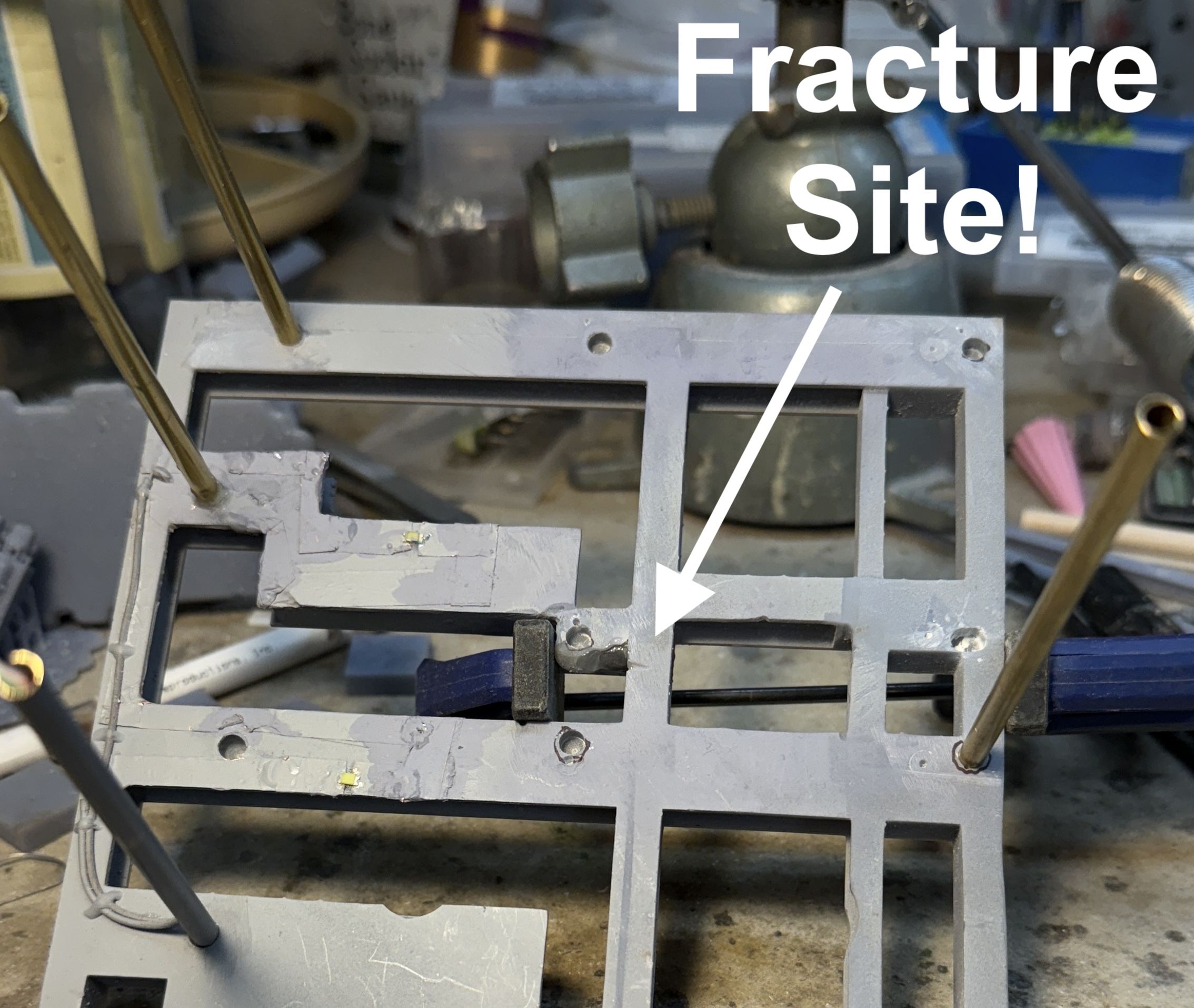
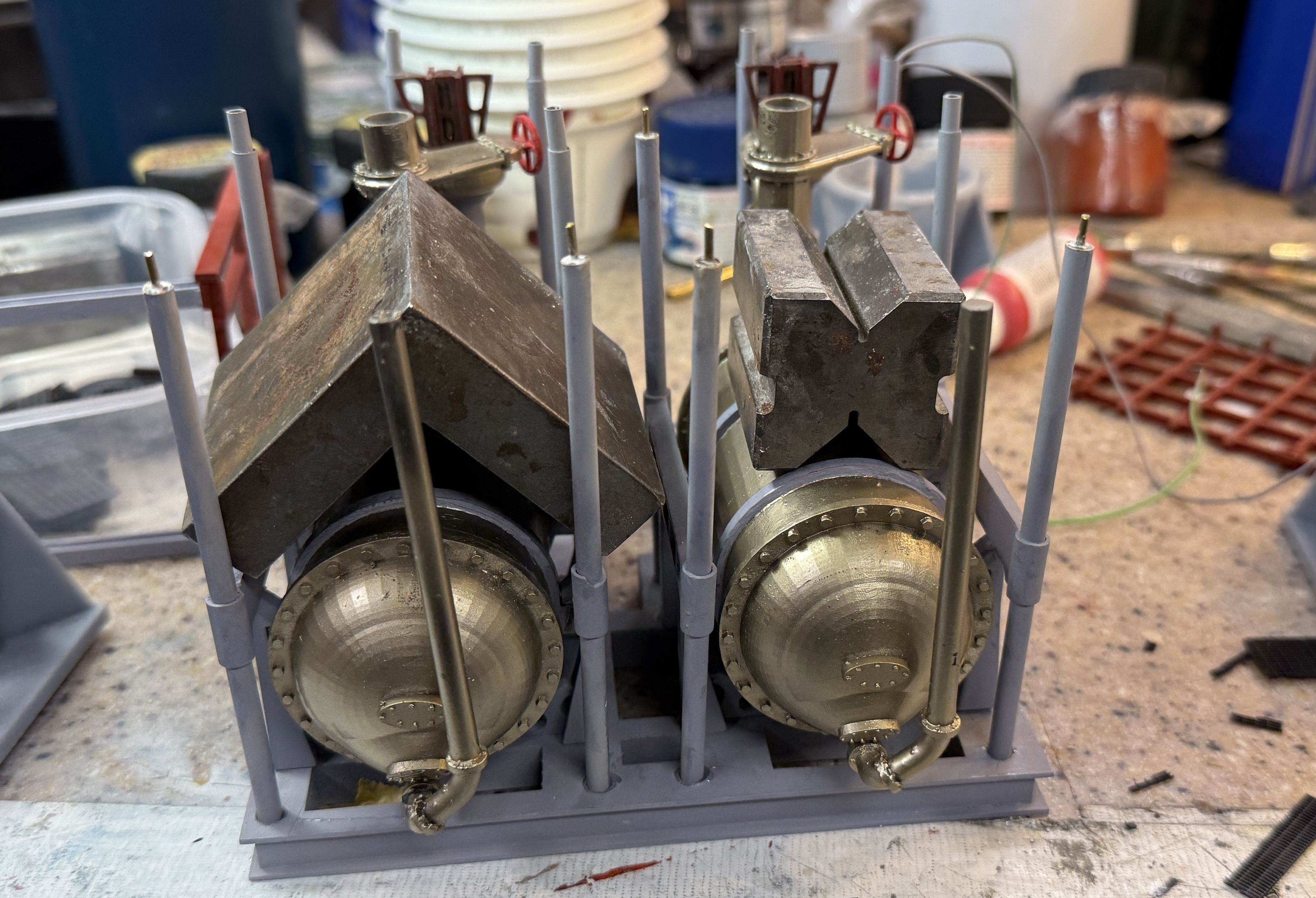
Friday wasn’t such a good day. I was on the phone with my friend Bryant, who’s building the base, and noticed that an upper joint of one of the vertical pipes out of one condenser was failing. One of the challenges of drilling resin to add metal rod reinforcement is that it can weaken the resin that’s surrounds it. I think that’s what was happening in this case. I repaired it with epoxy while still on the phone.

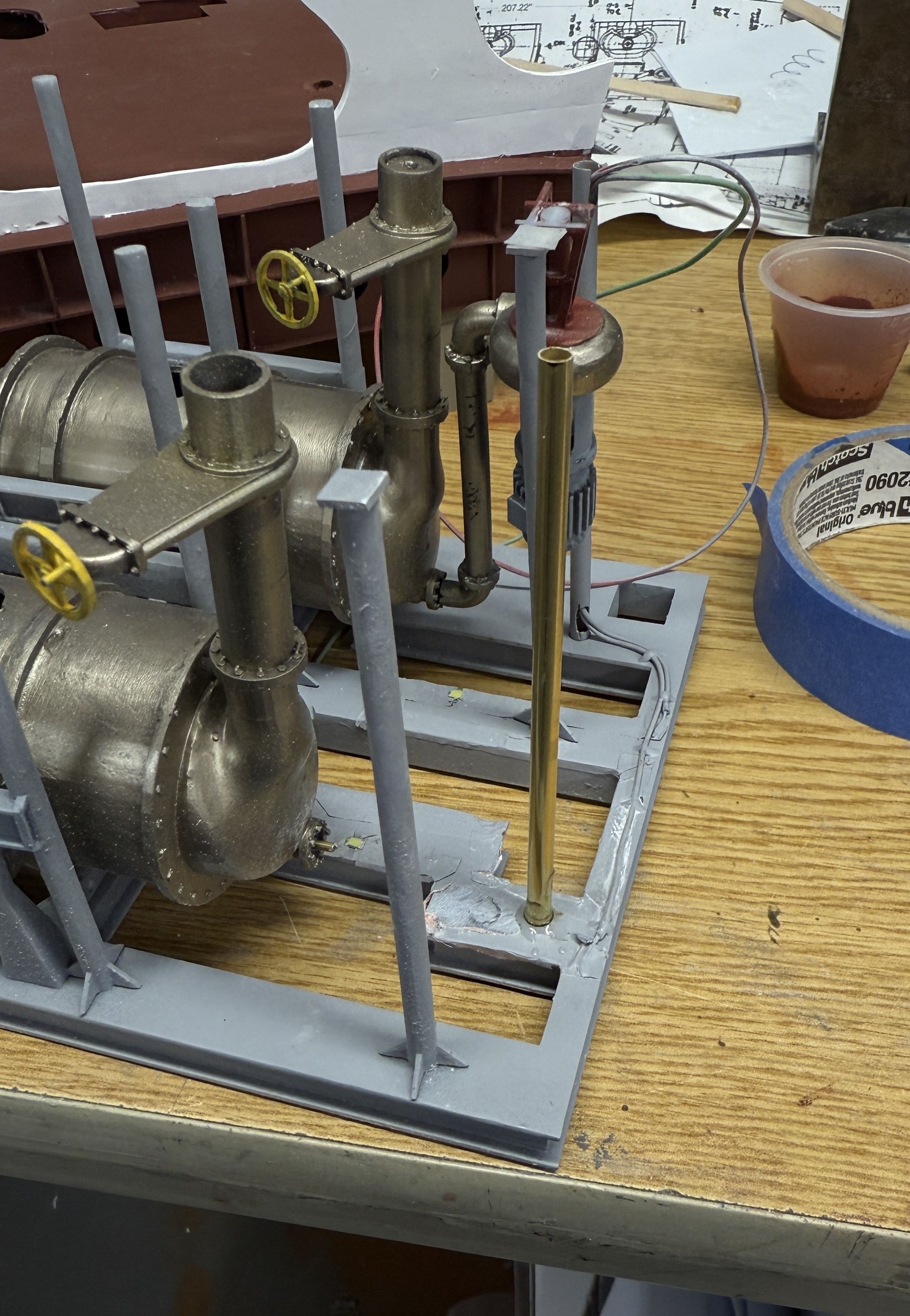
I then put the TG deck and condensers onto my pull-out tray on the main workbench that is 90º to my movable bench. It was too close to the edge (apparently). My new desk chair is pretty big and tend to run into thing behind me when I swivel it. Usually it knocks over the trash receptacle behind me. NOT THIS TIME!. This time it knocked the entire TG assembly onto the floor. Thank goodness that all that was glued on were the condensers and the TGs themselves. IT BASICALLY WRECKED IT!

Enough of the support columns were whacked that I removed the rest of them. All that remained unscathed were the brass ones. So that’s the bad news.

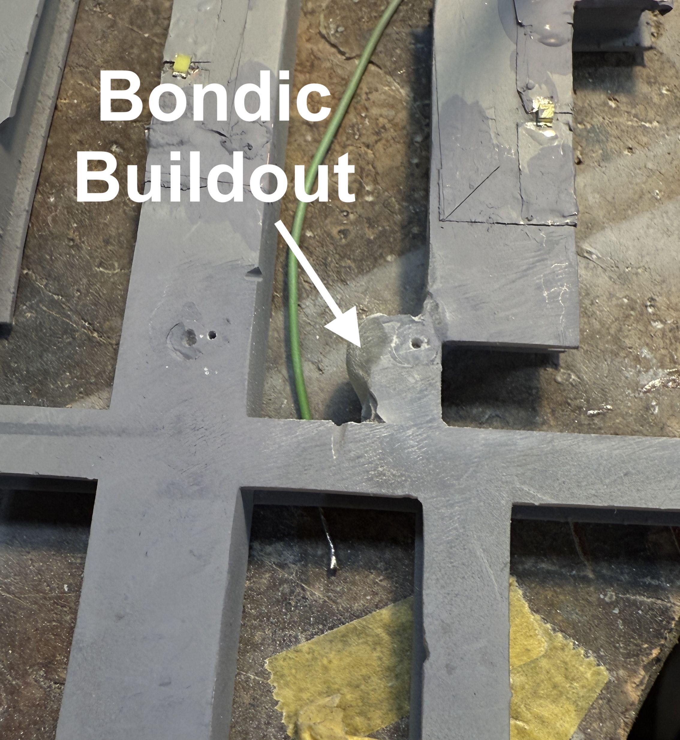
In addition to the condensers themselves, there was some damage the foundation frame. I took care of it with Bondic.

There’s always a silver lining. In this case that optimistic view was my opportunity to improve the things that I didn’t like about what I have made originally. I had printed the entire condenser assembly as a single part which led to some significant compromises. I also didn’t like how the suspension frame came out. It wasn’t staight or parallel and I didn’t like it. Lastly, the resin columns were warping and weren’t responding to my attempts to straighten them. This catastrophe made it essential to fix these things. I keep saying, the biggest advantage of building custom with your own designed and 3D printed parts is the ability to make new ones.

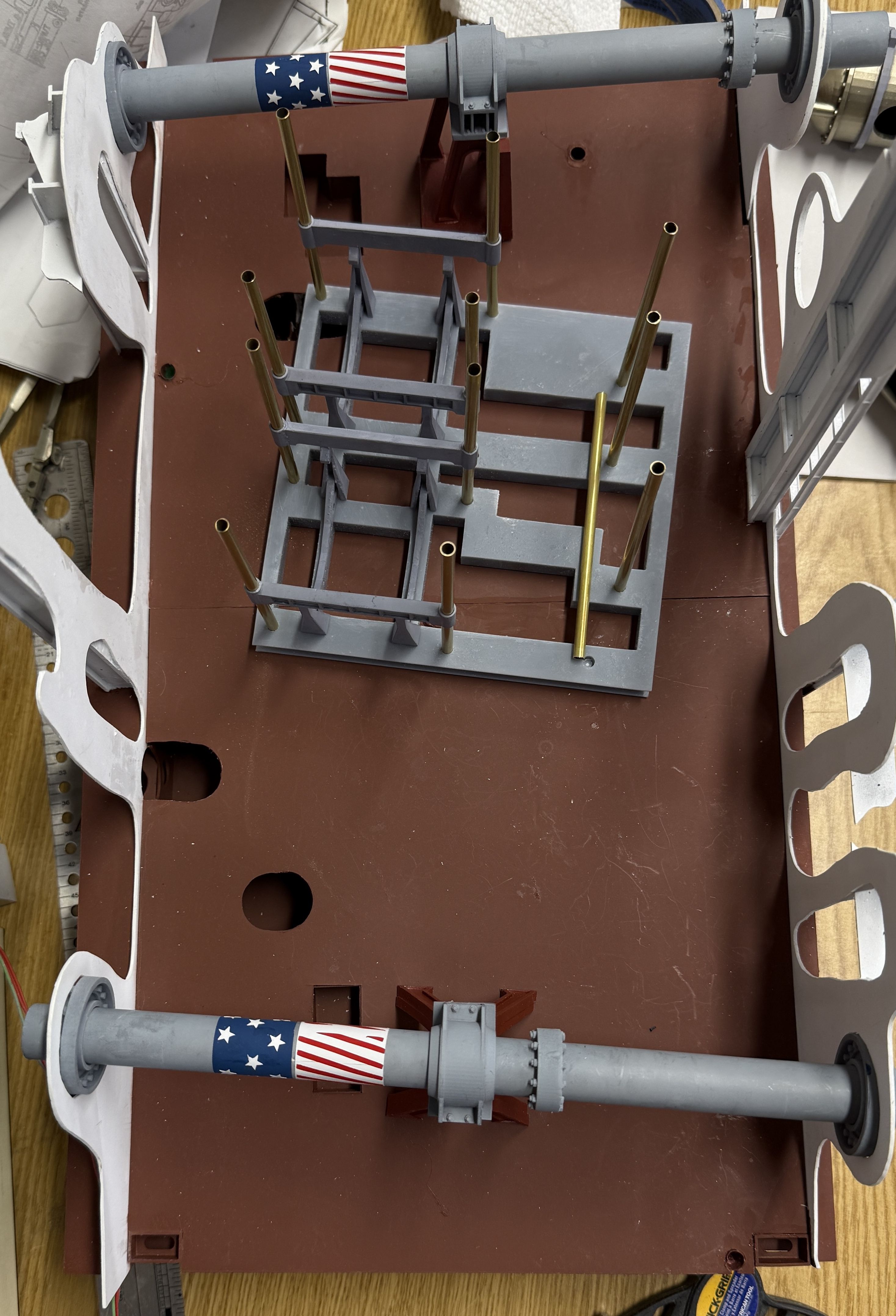
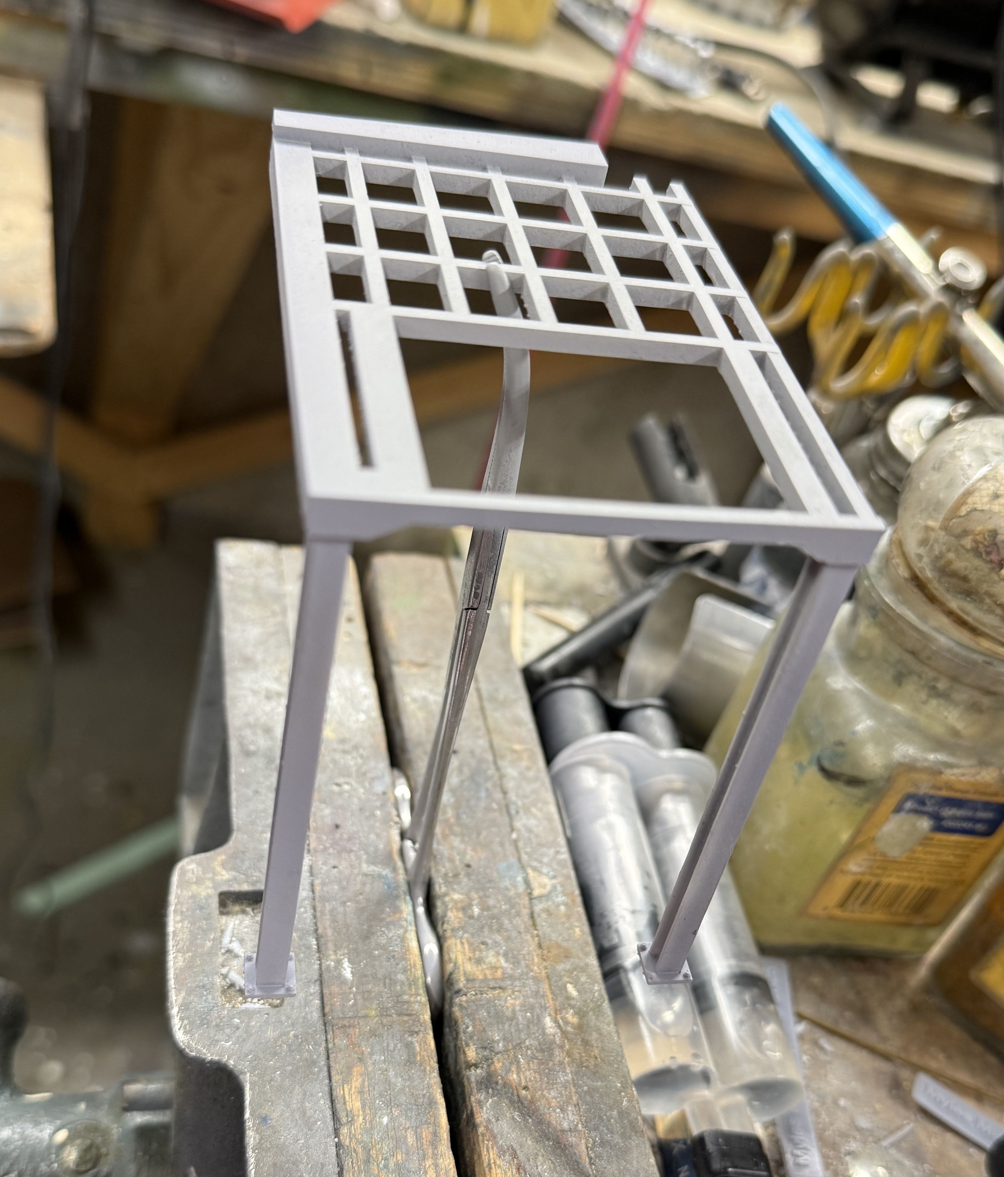
​I am substituting brass for all the columns like I did on the mezzanine decks. This neccessitated redesinging the condenser mounting frame to column interface. I had printed the frames with the columns. It seemed like a good ideaat the time to ensure alignment. Except the alignment was off. There were other aspects of the mount that were troublesome especially the cross-brace that tied the two sides together. It was too thin, broke and required a jerry-rigged doubling that looked awful, but no one would see it bured under the turbos. I didn’t like that either.

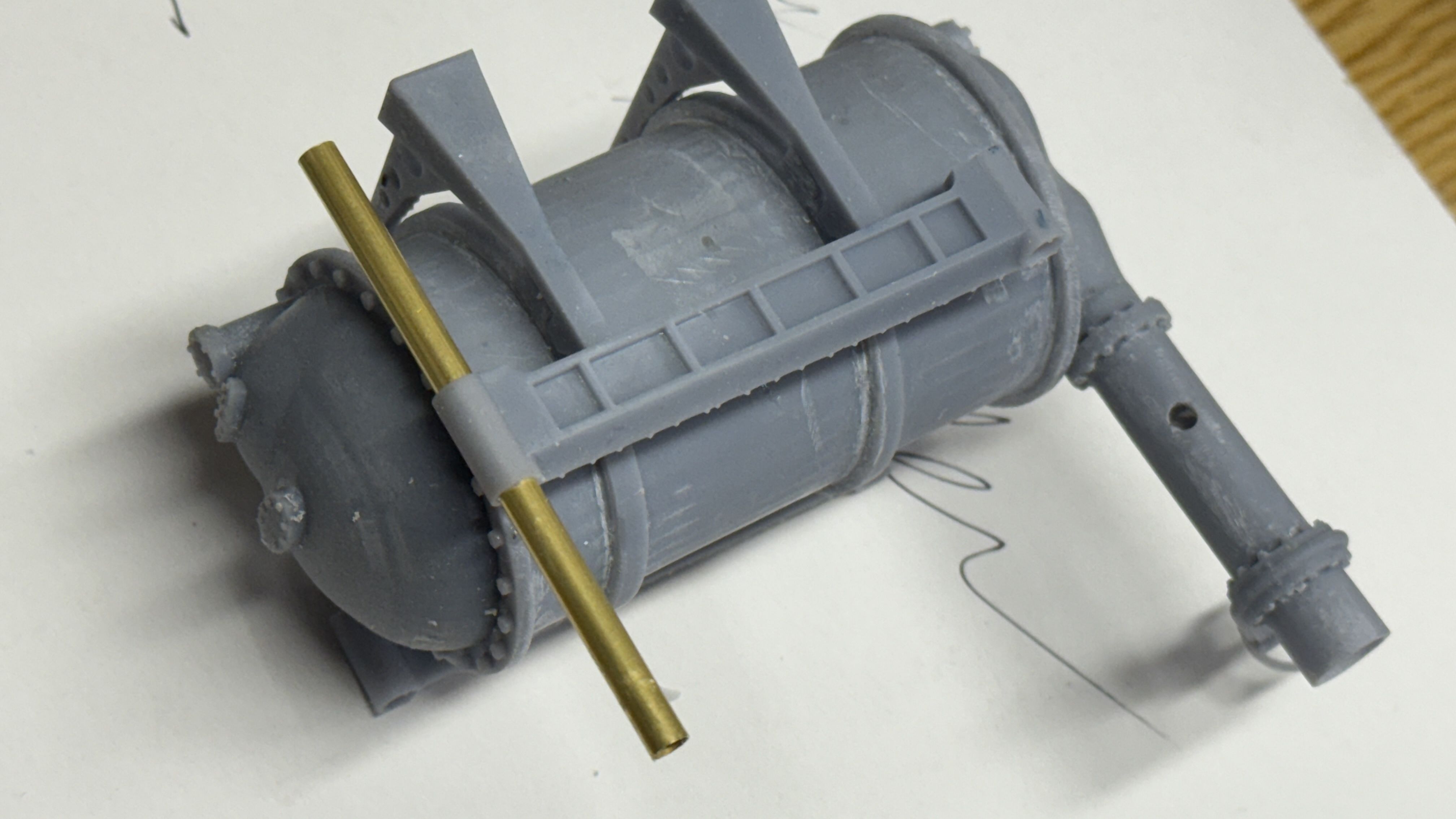
The new design has tubular structures that capture the columns. It’s not exactly as the ship does it, but it will be more effective with the materials I’m using.

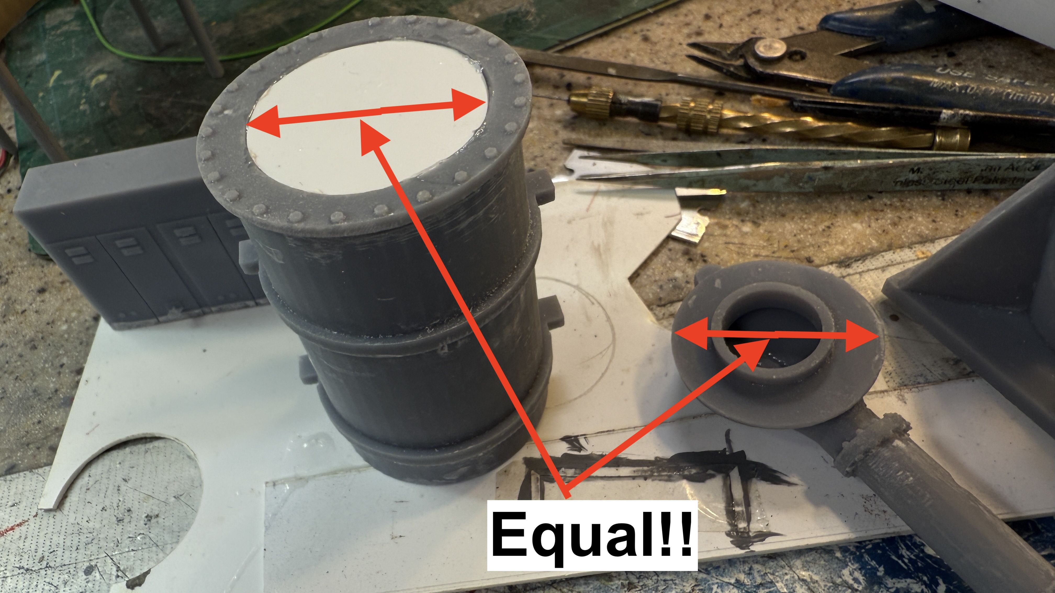
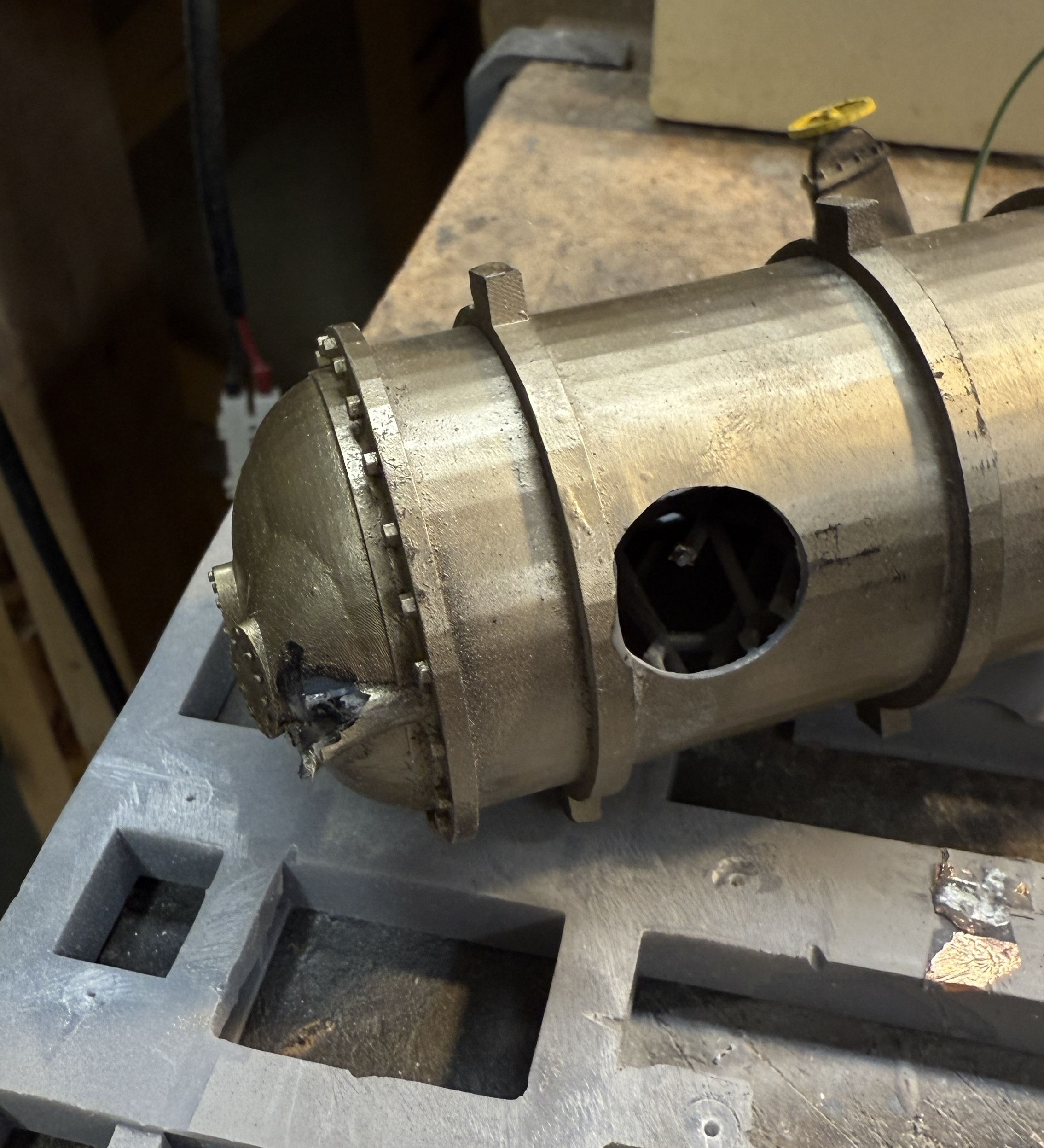
The other changes dealt with designing the condenser itself for better printing. I separated the main parts and am printing them individually. The original had the interior of the solid structure hollowed out that required a large drain hole at the bottom. In this iteration, I’m printing the central part as a simple, open cylinder that will print much more easily, and the only surface details is the bolt circle one end that has no suports, ergo no damage to worry about. All of the parts having adjoinng sheelves to assist in assembly.

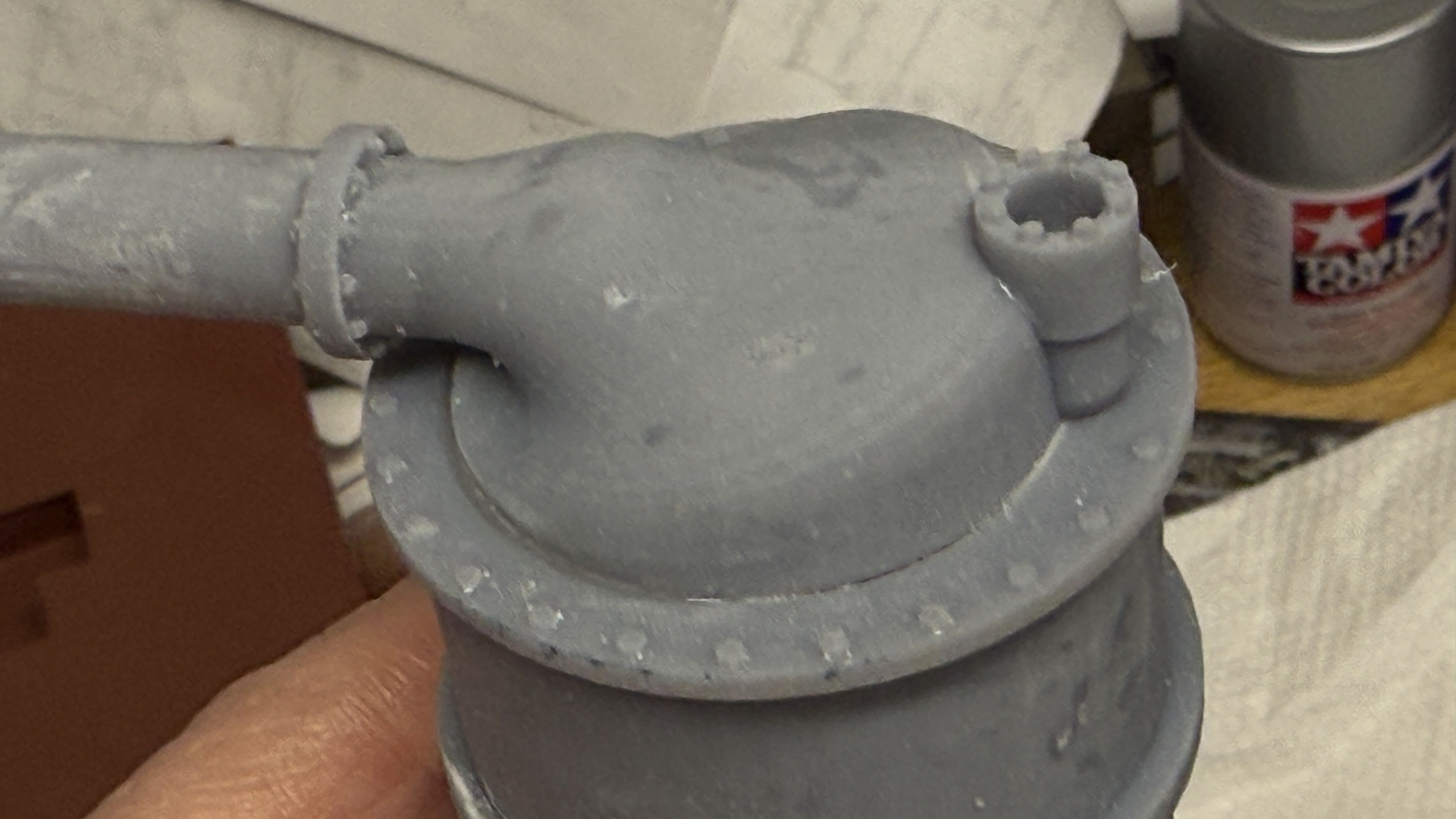
I need two and the first set just finished on the printer. 3 out of 4 parts were perfect. The end bell without the down pipe dlaminated between the bolt flange and the dome. It looks lke a drawing error where the parts were in actual contact. Meanwhile, I started the job again since the good parts will work and I’ll print the other as a separate job. It’s much lower and should print in less than two hours.

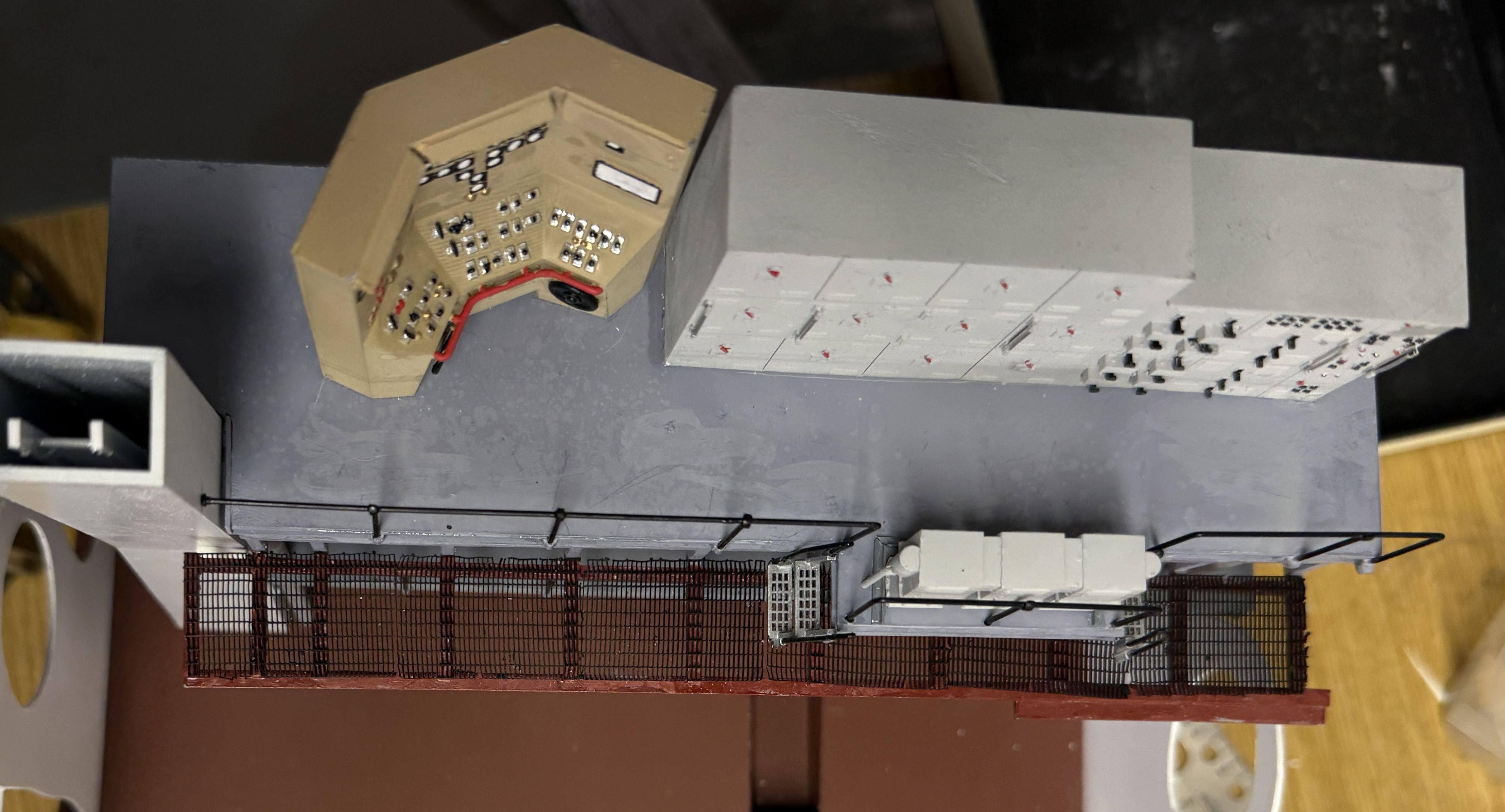
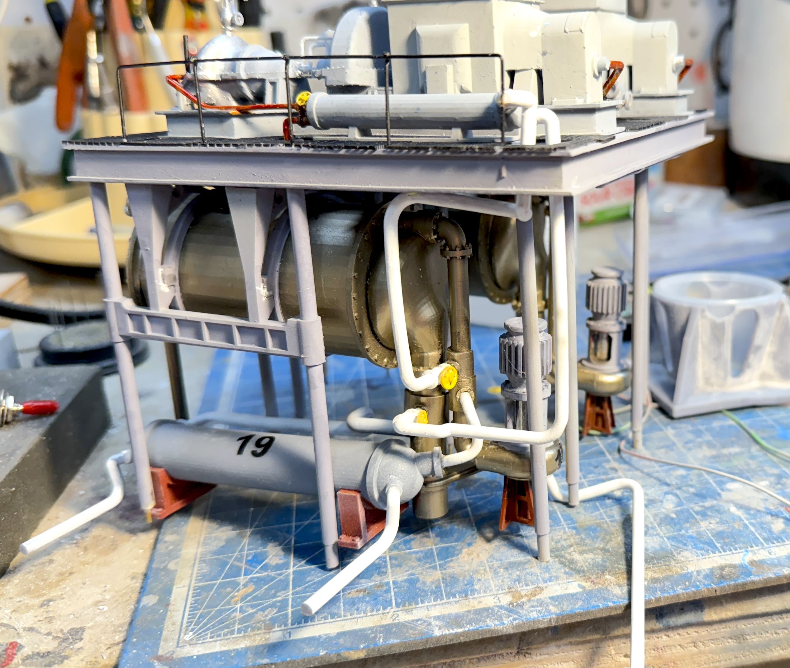
While the printing was progressing there was more to do. I almost finished building the mezzanine deck. I’m trying an experiment by using the 3M high strength transfer tape instead of glue. I did test with one of the extra cabinets and it seems pretty strong. Gosh I sure hope so. It makes the joint perfectly clean. After adhering the switch gear cabinets, drilled a hole for the control console wiring. I quickly found out that I could stuff all four wires down the 4mm brass tube so I soldered the ground from the console’s lighting to the ground connection from the other LEDs. It’s not a pretty joint and I may make a little junction box to hide it a bit.

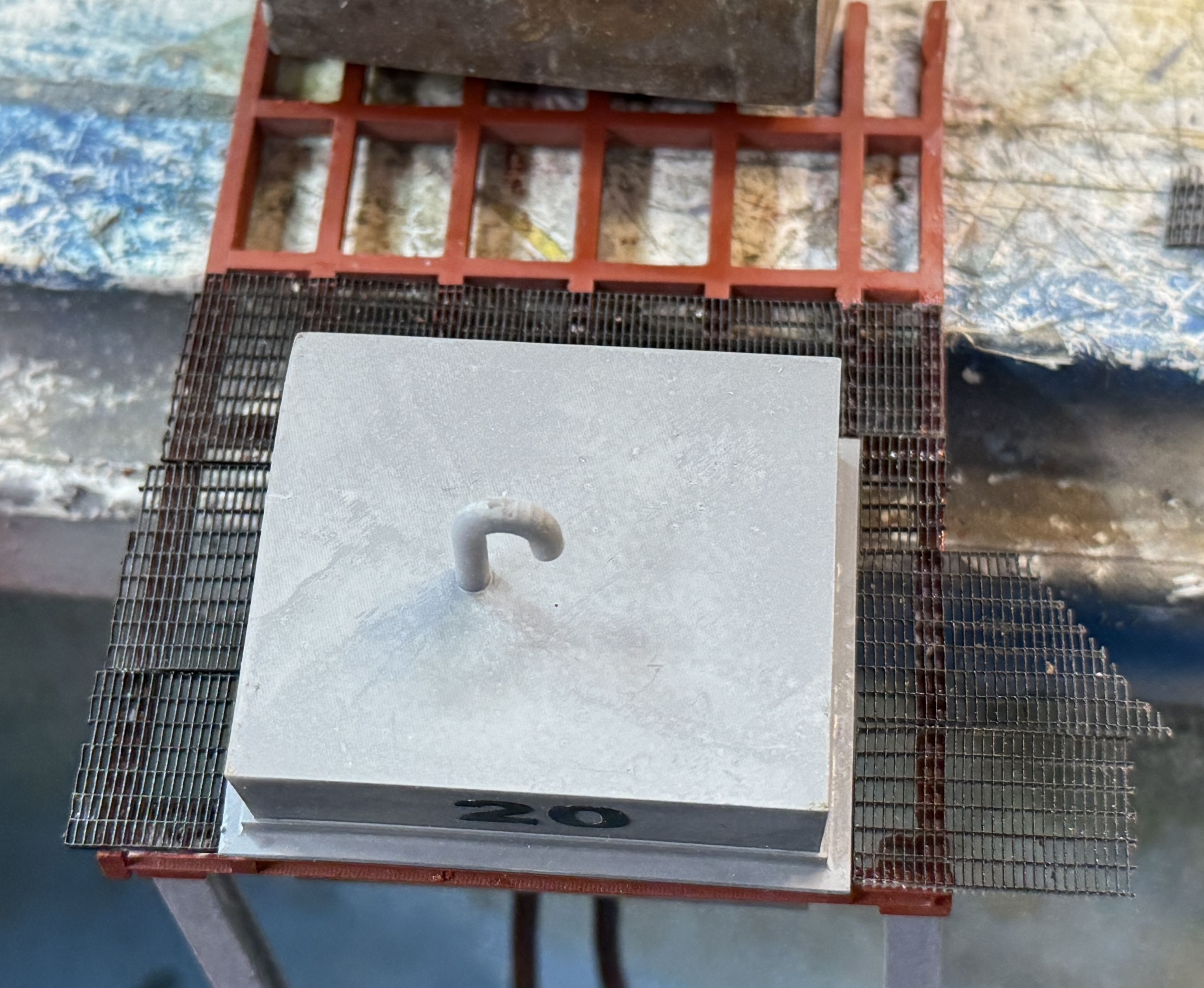
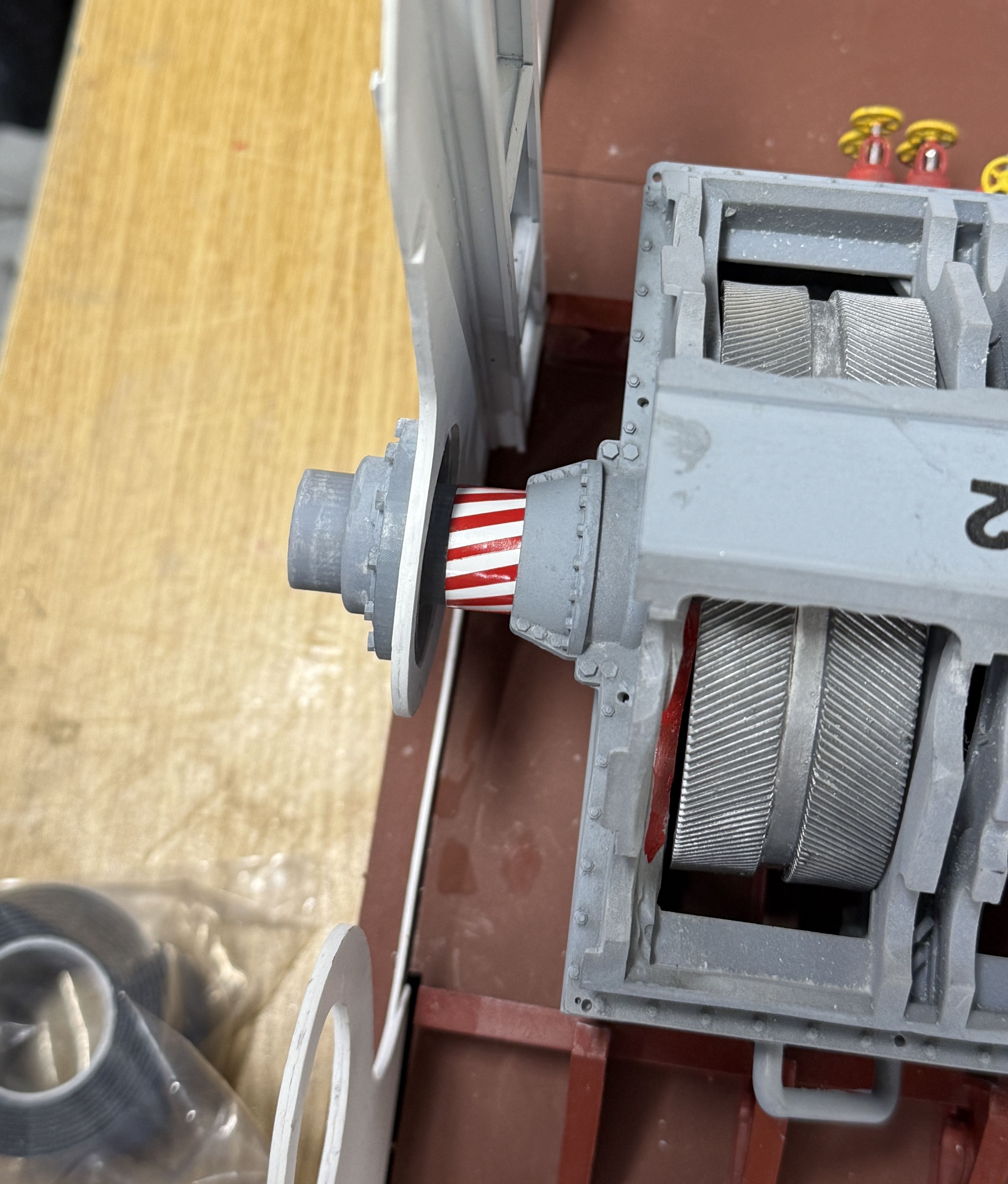
The other end looks like this.

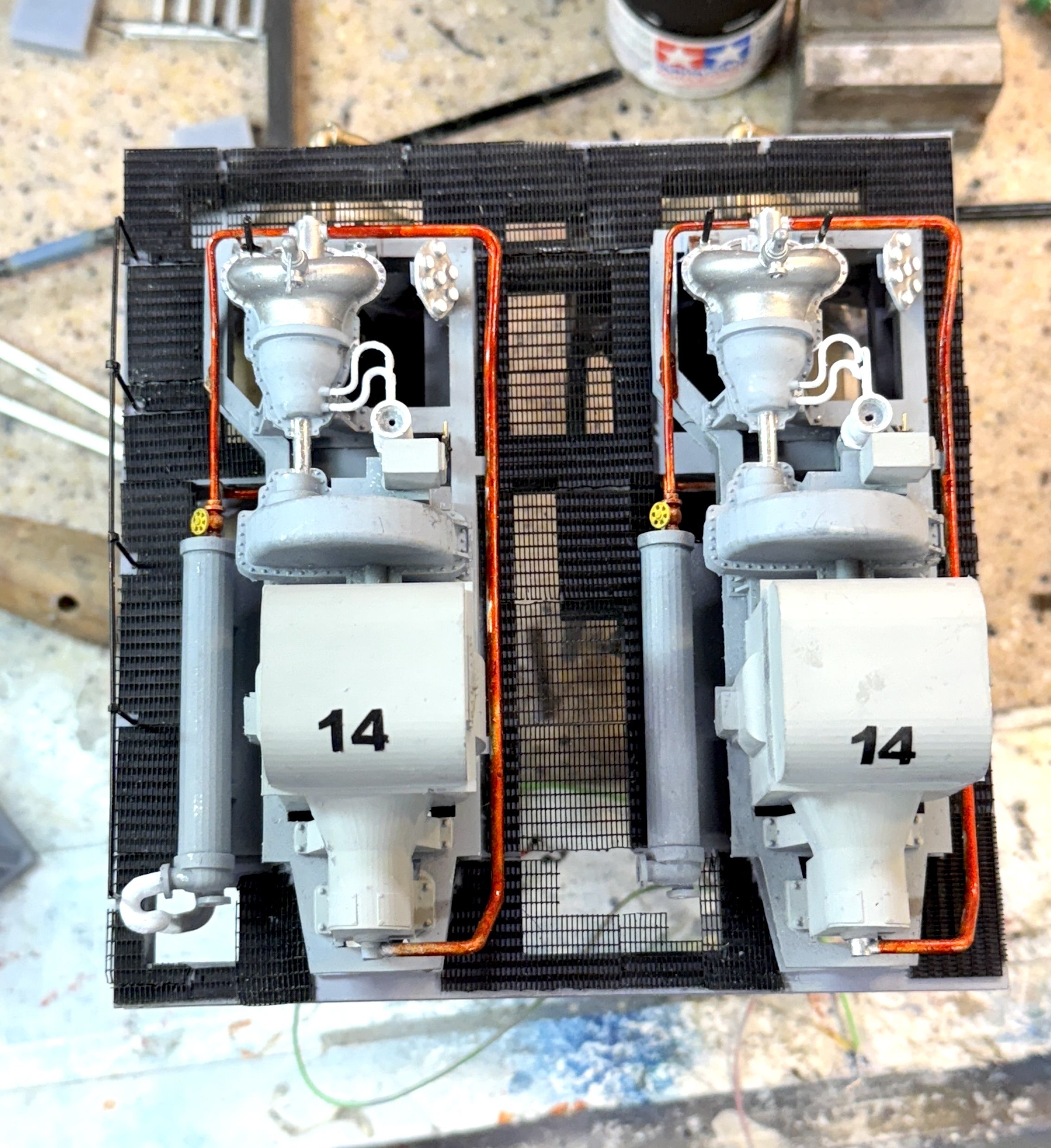
Here’s the mezzanine with cabinets permanently attached.

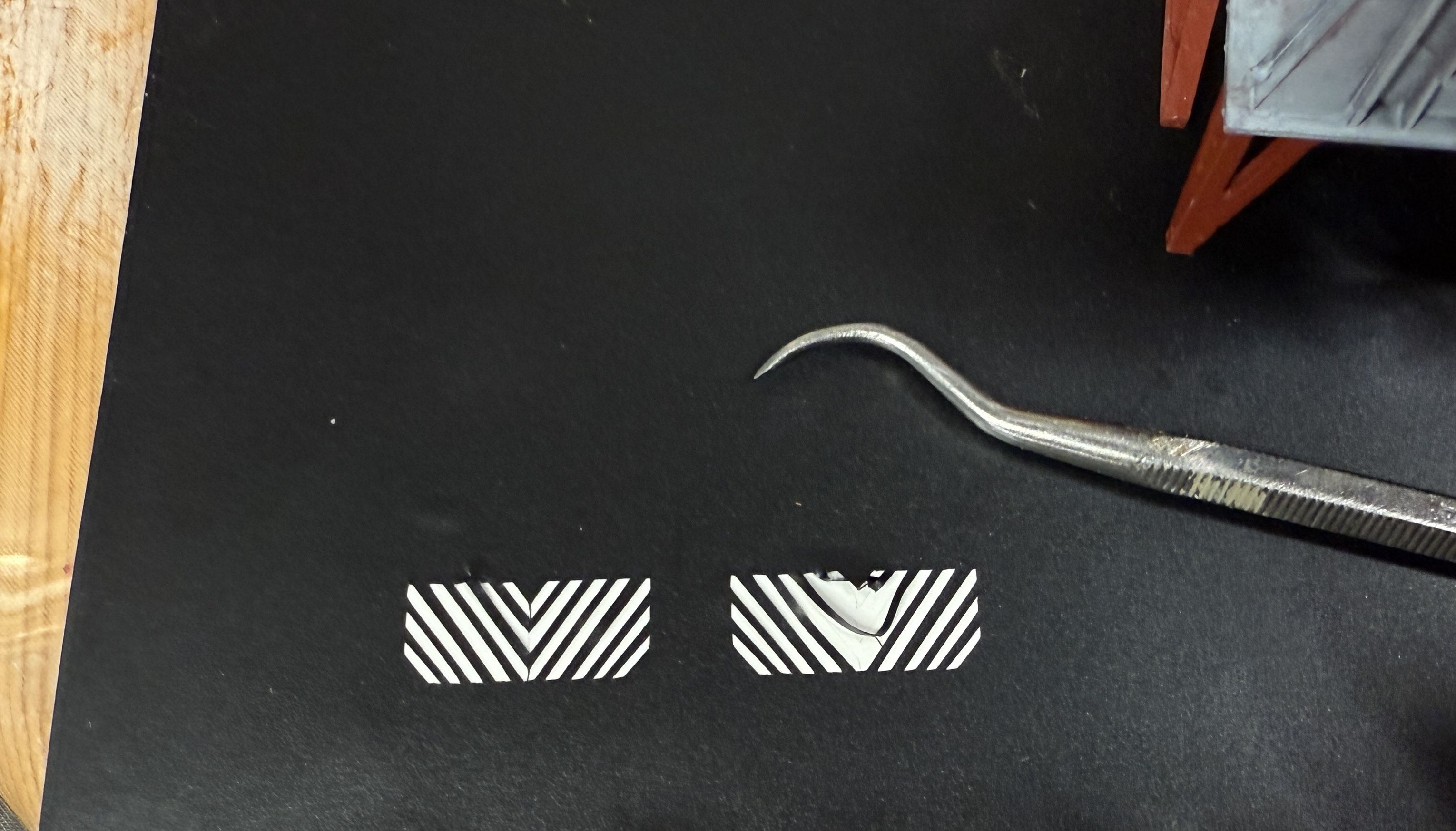
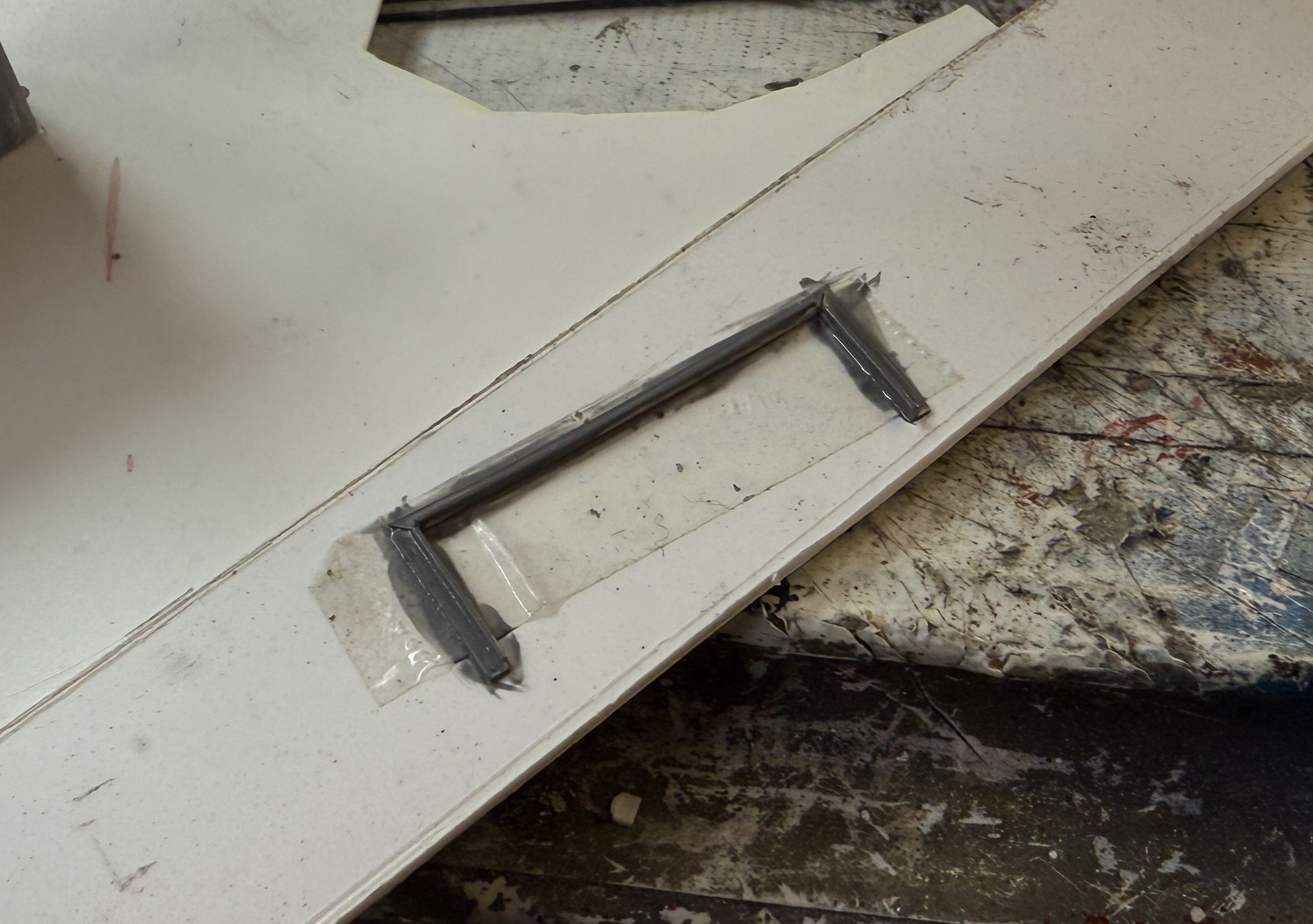
There’s a small angle iron frame at the base of the triple lighting transformes. I painted them off the model by sticking them to some Scotch Double-sided tape. I attach them tomorrow.

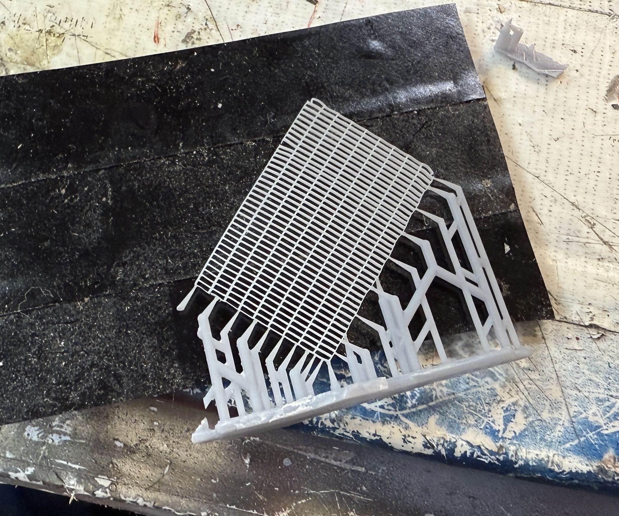
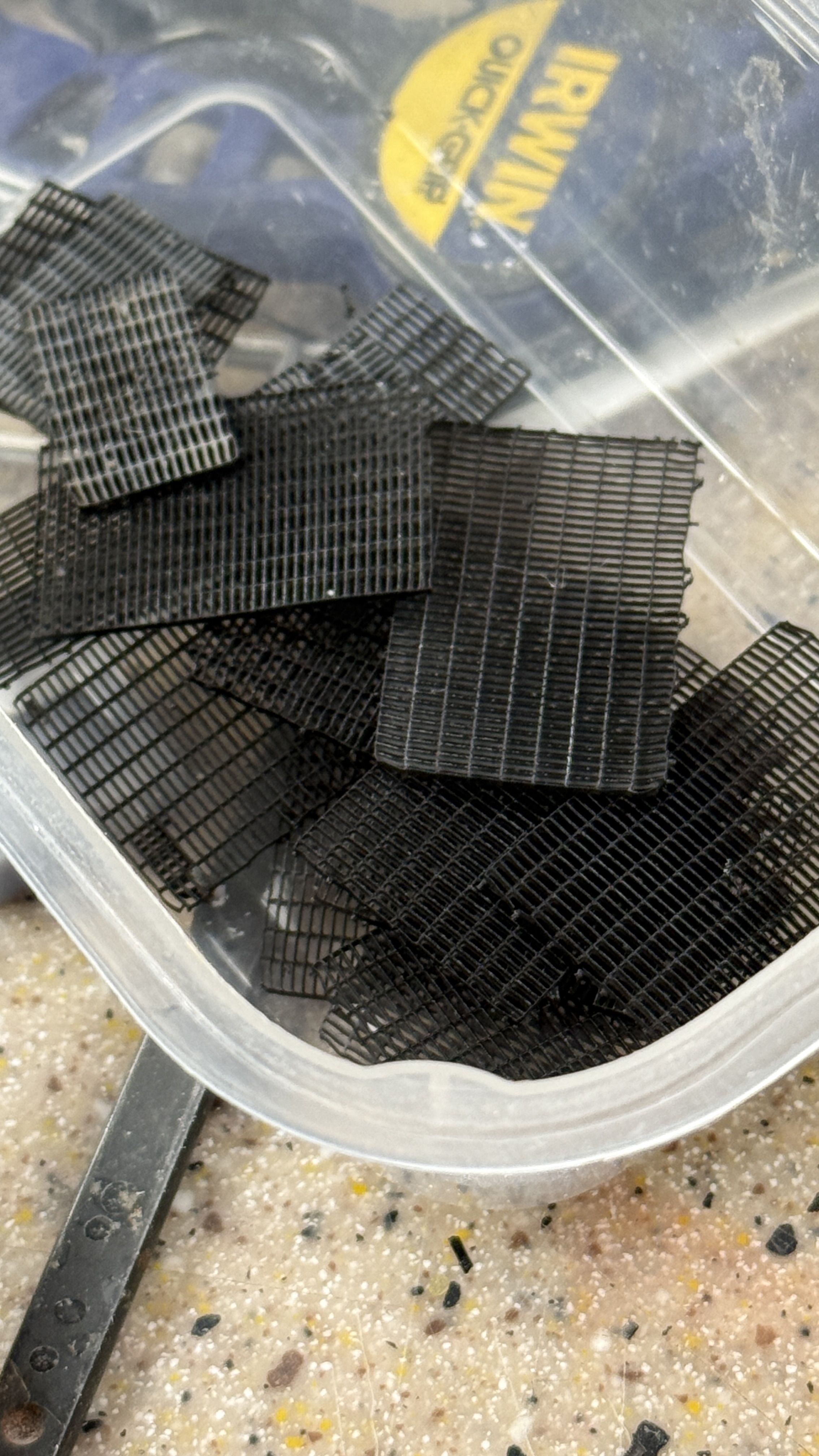
​What remains on the mezzanine is the railings and floor gratings plus some more touch up painting.

While I’m waiting for all the replacement turbo gen parts, I will keep moving through those things that I can assemble. Next up will be the evaporator decks. I have to get the vinyl cutter working. I want to make some of the graphics that way. Oh… I might have found a vendor to produce some 1:48 sailors in proper engine room dress. He’s from Greece and I saw his stuff on eBay and Etsy. If it works out, I will publish his information.

4 Likes

My Grandfather would say that things go wrong some days. My father would add to that why are there so many days like that?

1 Like

As long as the sum total is forward progress, I’m happy. The beaty of these kinds of projects is there is always something accomplished each day testifying that I was there and doing something productive. It makes retirement very rewarding and not many folks at my age can say that.

The newly minted condenser parts are working out well… except for one little slip up that needed an on site correction. While my intention was to have bosses on the end bells that would engage in a smaller opening at the condenser end. But that’s not quite how it worked out. My hole was as big as the outer diameter of the bell. So I had to fill the hole with some sheet styrene epoxied in place and then epoxy the end bell on top. While it was annoying, applying some conventional modeling skills worked out okay.

On the first one above, I forgot to cut the hole for the boss. I ended up grinding it off flat and just glued it straight on. I do learn… the second one I cut the hole while I was cutting the styrene circle and it was a simpler job to glue it in place.

While this was going on, the rest of the new design was printing. This included the other end bell and the hanger frame. The other end bell did have the classic 3D drawing error. The bell portion of the drawing was not in actual contact with the flange. As I zoomed in I could see they were actually not in contact. It prints it EXACTLY as you draw it.

The end bells are both on and look okay.

Notice the new method of connecting to the columns. This way I can use brass all the way around, have no warpage, and because I are the becauce I drew the parts square with the hanger, the columns will be nicely plumb. I am going to see if I can glue the condenser to the hanger BEFORE gluing the hanger onto the foundation. It will be much easier to hold it inplace during curing.

I have to take these outside tomorrow to do the bronze painting again using the Alclad black primer and the mixture of pale burnt metal and titanium yellow metallic lacquers.

And while all the curing and printing as going on, I was finishing up the electrical mezzanine decks. It is almost 100% finished. All that’s left is working on some uneven tocuhup painting.

The conduit leg was about 1/8" longer than the others. This was unintentional, but I left it that way so the wiring would be directed straight down the floor opening. It turns out that with the escape trunk epoxied in place, that the entire assembly had to shift a bit forward. This put that longer leg no longer aligned with the floor conduit. I trimmed the longer let with razor saw, holding the entire build in my left hand. I’m not sure about just butt gluing all the legs onto the hold floor. Instead, I’m going to epoxy some slightly smaller tubing into the legs, drilling the floor for the smaller tubes and then epoxying them in places. This will provide better positioning control and better gluing.

The grating went down pretty well and it’s the first walkway getting it. I think it adds tremendous detail focus to the model.

Looking straight down really show just how ephemeral the grating is. The red expose edge of the walkway will be inserted into the H-beam structure of the TG foundation and will not be visible any longer.

On another front, here are the three paint cup holders I designed and printed. The two on the right are version 2 with the finger clearance facilitating getting the cups out. I also thinned the webbing. There’s not real load, but I just like the way it looks. I did want them to have a bit of heft so they wouldn’t move all over the plave when you stick a brush into whatever they’re containing.

​Tomorrow, all the repairs would be complete inclduing paint so building the turbo-gen deck will continue, hopefully without further angst.

5 Likes

Ryan informed me this morning that I should have left a gap between the electrical control panel and the switchgear cabinets. I don’t have any wire slack to moved it much and the transfer tape is holding like crazy and I don’t want to disturb it. He agreed that we can live with it. When I installed it I also thought that maybe I needed a gap there. I did mask and respray the back of the lower electical cabinets.

I added the rest of the plumbing to the new condensers and then took them outside to prime them with the Alclad gloss black. The gloss black gives the metallic paint more depth. You need to lef it fully cure for 24 hours, even though it’s dry to the touch now.

I got to work on preparing the brass columns and laying them out on the turbogen foundation. I should have known that changing the mounting system would cause me more work. It did. The column spacing changed requring new column hole locations. In most cases, the spacing change didn’t cause a problem. But in others it caused some big ones. The spacing was wider in both directions. It placed one of the holes at the edge of the frame. I solved this by building out the shape with Bondic and then was able to drill it. That small pilot hole is from the old hole locations. When I cut off the resin columns I marked their locations with these small holes not realizing that my redesign would negate all of them.

Then I had a slightly larger problem. I thought that I had laid out the new locations pretty carefully using a transfer punch to mark the hole locations using the new frames as a guide. I got 6 out of 8 locations correct. For the other two, I had the longitudinal spacing too tight by about 1/8" collectively. When I attempted to slide the frames down the columns to test the fit, the closeness put so much stress on the frame that it completely fractured. I am in the process ot lengthening the holes in the direction to get more length and epoxied the fracture back together. None of this messiness will be seen. It’s the bottom and won’t be possible to view. You can see the start of the hole-stretching exercise.

At this point it might be easier to simply reprint the entire frame with the new hole locations in the print. I’ll see how this all works out. After I wrote this, I AM going to reprint the frame so the holes will all be placed as they are on the drawing. Here are the columns sitting in the frames.

Meanwhile, if that wasn’t enough angst. I thought I measured the new columns carefully. I used the protruding length of the two existing brass columns as guides. I cut the 10 columns from the new tubing that arrived yesterday on my mini-cutoff saw. They were all nicely the same length using my DIY guage I made for this cutter. But they were all short!! I’m not sure where the error came from since I had inserted the new tubing in the hole before scribing the measured length. Oh well. I had enough tubing left over to cut 9 tubes and just order another three tube pack from Amazon that will be here on Friday. There’s plenty of work to keep me busy building the other sub-assemblies.

5 Likes

Things are starting to get interesting (in a good way). The remade aux. condesers are finished and ready for installation. The new foundation frame is printed and in the ultrasonic. It will be put into action tomorrow. And I got the Sihoulette VInyl Cutter into action making the number callout labels for all the equipment to line up with the key that’s going on the case.

Again, I took the condensers outside to do the metallic coat. This time instead of spraying the Alclad Pale Burnt Metal and following with a light coat of Alclad Titanium Yellow, I just mixed them beforehand and airbrushed it on. Worked fine. When dry I masked and painted the suspension rings (which I didn’t do the last time) and then handpainted the condensate pumps details.

I replaced more resin columns with brass on the evaporator foundation, using the shorter ones from yesterday’s screwup.

I had reviewed all the tutorials, and was at a point that I needed to get vinyl cutter going. The reason: The propeller shafts are installed soon, like before all the outer units go in. This means that their graphics have to be applied soon. I’m planning on making vinyl cut masks to put the stars and stripes onto blue and white painted base coats. I waas thinking originally about using custom decals for this, but wrapping them around the shaft didn’t excite me. This is one of the two pass-through shafts in engine room #3.

All the major points of interest are going to be numbered. I laid out the numbers on the Sihoulette Studio graphics package. With my long experience using this kind of software, it didn’t take long to learn it. What I didn’t figure out was how to make it ACTUALLY work. That took about 20 minutes of fussing. I hadn’t locked down the cutting head deep enough in its holder. This resulted in the machine running like mad, but cutting nothing but air. I also found the materials setting dialog to set the parameters for each kind of material. I found plain vinyl, and used the recommended settings. It started cutting immediately. What remained was finding the smallest font size that could be accurately cut. It turns out that smaller that 24 point, while cutting, didn’t work out so well. I made two type sizes, 24 and 30 and cut the numbers.

I used one of the test numbers to see how well it stuck on the painted resin. It sticks like crazy. This was an extra turbo.

Here’s the cutter at work. The cutout areas in the bottom of the sheet were my test cuts. One of the tutorials suggested doing the tests at the bottom of the sheet so you can view and remove the samples without taking the stock out of the machine without disturbing any registration.

Here’s the cut sheet. Some of the numbers detached too easily from the backing sheet. I bought the transfer tape at Michael’s Crafts. This is supposed to enable the cut item to be plucked off the vinyl backing sheet and then transfered to where you wanted to put it. I mistakenly bought tape for glitter vinyl which is a completely different material. So I tried Tamiya Masking Tape and it worked perfectly. It has enough tack to pick up the cut peices, but then let me apply them to the model with no difficulty. I used a burnishing tool to burnish down the numbers before removing the Tamiya tape. Another tip I learned was to draw and cut a box around the graphics enabling you to weed (term used to remove the unwanted parts of the cut) just the area you’re working on and not having to peel and destroy the entire sheet.

Here are the number on the electical cabinets. Oh… look! Two “25s”! What idiot is actually doing this job. I’m glad I took this picture. I will fix tomorrow. Now we’ll find out how tighlty the vinyl really sticks.

And the actual turbogenerators…

And the evaporators… which are also now epoxied to their frame. I have to add floor gratings and it will be ready to install on the hold floor.

And the front side…

I’m concerned about the strength of butt joining the columns to the hold floor. These joints are ultra-critical. I thinking about filling the open ends of the tubing columns with J-B Weld epoxy putty, then drilling and installing some brass pins. The pins would provide a more solid joint.

The job is accelerating and more finished stuff is going to be appearing each work session. The base is also nearing completion. I’m going out on the limb and saying that sometime in September the model will be done.

5 Likes

Not much done today. My daughter had a very rare major flat tire and needed to be ferried around this afternoon. But I did get ALL of the numbers applied to all the required parts. I’ve also finalized the stars & stripes graphics drawing that will be used to cut the pieces in the new vinyl cutter. I found out that even though the vinyl says, “Permanent Adhesive”, you can still carefully pry it loose and replace any errors, like I did twice. The new TG frame is ready to be trimmed and post-cured, but that will have to wait until Monday. Have a nice weekend.

4 Likes

​Happy Monday. Back in the shop! The new Vinyl Cutter produced some more good stuff; the propeller shaft graphics.

Before I could cut anything I had to remove the black vinyl from last week’s number-cutting. That wasn’t easy. It should be, but because I had the cut set too deep, all the numbers and their bounding boxes along with the backing sheet were cut all the way through to the carrier sheet. The carrier sheet is adhesive coated, necessary to hold the stock as its being reeled back and forth as the cutter works. Normally, you just peel the entire sheet off the carrier apply another piece of vinyl. But with everything cut clean through, I was left with all the separate strips and individual characters and any holes (like the centers of the number 8 or the triangle in the center of the number 4). This took over a half hour with tweezers and hobby knife to peel them off without damaging the carrier.

Stars & Stripes Decor on Prop Shafts:

Besides the US patriotic theme, the stripes help the crew determine how many turns the props are making and makes it clear that there’s a 32" dia., solid steel shaft spinning in their space. I drew all the designs on a single page in the Sihoulette design software, but you can selectively choose what you’re actually going to cut. This was very useful with some parts being cut from white and red vinyl. I thought I had bought blue, but didn’t, so the blue areas are masked and airbrushed.

The stars were a challenge to lift off the backing. I understand why people buy the special transfer tape for vinyl cutting. The Tamiya Tape worked well, but it’s not transparent enough to really see how the cutting will be applied to the workpiece. I’m going to get the real stuff. You have to be careful when pulling the details off the big sheet. If they don’t come off the first time, you run the risk of the array getting out of register. Some of the stars did get loose and took some fiddling to get them applied.

The result were pretty good. Ryan was happy to see that I’ve added some “Crew applied” graphics to the model.

i also got the replacement turbogen foundation post-cured and all cleaned up. The re-drawn version now has the perfectly sized hole for the 4mm columns. The previous one had holes for a scale of 7" diameter column, and needed to be drilled larger for the 4mm brass columns. Now I have perfect and plumb fits for all the columns. Sometimes it takes more than one try to get things right. Just ask Elon Musk about luanching his Starship.

I then started doing the new circuits for the LEDs. In this instance I’ve added a 3rd light to give more illuminaton on the lube pumps and lube oil cooler in the lower deck area.

When the attachment leads are soldered on, I will assemble the columns, then prime and base gray. This week should produce some good things. My friend Bryant, called today to get one final dimension check to use when cutting the ogee trim pieces that surround the base plate. When I get the finished base I’ll bring it to the plastics house and have them measure it for the clear acrylic purchase. I get the acrylic CNC cut leaving a pretty smooth surface requiring very little sanding before cementing.

3 Likes

Today was one of those days where everything was working until the very end when it stopped. I continued to produce useful things from the vinyl cutter, got the evaporator deck fully covered with grating, prepared the columns for mounting to the base, and continued work on the new Turbogen platform. It was the latter that we South at the end of the day.

I made the warning strips on this rectangular tank at the lube oil pumps. It was easier than masking and denser than my custom decal would be. I think it works well.

Again, pulling the strips of the cut vinyl sheet required patience. I made two sets just in case, and it was the prudent decision. One of the stripes folded over itself and got too annoying to continue with. The second one worked out okay. This is what the sheet looks like after “weeding”. In this case, the weeds are the things I needed.

I glued the legs into the new TG foundation using epoxy. Before doing so, I filled their bottoms with J-B Weld epoxy putting, in which to install mounting pegs. I also filled the tubes on the finished decks.

After installing all the columns and epoxying them in place, I worked quite hard to get the mounting frames down onto the tubing. I had to worked them down side by side. I then took it outside to prime and after dry, shot a finish coat of Dark Ghost Gray Mission Models Acrylic paint. I was very pleased with the outcome.

While the paint was drying I prepared the other decks for the mounting pins. On the TG decks, the epoxy putty didn’t adhere to the tube and when I pressed on it to locate a center hole, and they slipped down into the tubing. I took a different tack by CAing 1/8" brass tubing into the 4mm outer tubing. I’ll use a 1/8" drill and this way the column will be stopped at the correct depth when the 4mm tubes won’t fit.

On the other decks, I added some thin CA to the epoxy plugs to stabilize them and then drill an apply the 3/64" rod. This worked pretty well and those are ready to install on the model.

I also grated the entire evaporate deck. This is actually fun to do and really looks great when done.

And then I was ready to attach the new condensers to the newly completed TG foundation and then…. This.

I installed the hanging frames UPSIDE DOWN!! I was paying so much attention to the tubing spacing and fit that I didn’t realize I was doing it wrong. And to add insult to injury, I had secured it all with thin CA at the tubing/frame joint. It was hard getting the frames seated all the way at the bottom, whereas they’re not supposed to be at the bottom. The tube connections should be in the middle somewhere. The solid arms should rest on the bottom.

So I took a flat-bladed screwdriver and pryed the whole thing apart. It was very, very secure. I had to destroy two of the loops getting the tube out and crushed three of the tubes to twist them to break the CA’d joint. But… I have a printer, the file was still on the machine, I have extra tubing, so tomorrow I will have new parts to assemble it correctly. This one assembly is becoming a real pain!

Onward and upward!

4 Likes

Today was a little of this and a little of that. The new condenser suspension parts printed as good as the first one. This time, I got them right side up. I put them onto the foundation frame with their columns sunk to the proper depth in the mounting hole… holes which I had to clean out from any reidual epoxy that would prevent columns from seating correctly. I slid the suspension frame down to seating on the foundation, and holding everything down tightly, added some judicious thin CA locking the columns in their correct positions. I removed them and took the new assemblies outside to prime them.

When primer dried I shot them with the color coat.

With the mounting like this with the columns attached, I checked out if I can glue the condensers on the their suspension frames off the foundation, making clamping much easier. I was able to do so, so tomorrow I’ll assemble them attach to the foundation. The holes lines up perfectly. The TG systems will be assembled tomorrow. I’m not expecting any more nasty surprises, but you never know. “Hope for the best and prepare for the worst.”

​I broke off a free standing pipe on the evaporators so I redrew it with some supports and printed another. I also printed a small detail; a gauge panel that sits on the wall of the main reduction gear. There is a group of sensing lines leading from this to places unknown which I may or may not add. It’s on the lower level sitting behind the lube oil pumps.

I found one more floor system that needs a small railing. It’s the ladder that goes from the lower to upper level. It needs a guard railing to protect crew from falling into the open ladder way. But, the girder system I designed is too diminutive to be drilled for the railing stanchions. I solved this by gluing on some styrene thick stuff below that will accept the rail. It won’t be seen easily since the hole deal is covered by gratings.

​Lastly, I painted the ends of the prop shafts red to signify that they are cut from something bigger.

3 Likes

Happy Monday. Got a lot more gratings done, and reprinted another set of them since I will run out. I knew I’d have to do that as there are some big surfaces that still need covering. And I finally got the TGs condensers and their respective turbogenerators epoxied in place. This was a big deal after the trauma of wrecking the first one. This one came out much, much better. I glued the low pressure and high pressure turbines together, so they’re ready for mounting in the model. I had to print some I-beam columns for the front platform that sits in front of the TG structure.

As planned, I was able to glue the condensers to their frames off of the TG platform, thereby avoiding having to clamp them using that jerry rigged dowel shim as I did the first attempt.

I tried to use rubber bands and Quickie Clampls to hold until the epoxy cured (5 minutes), but the parts kept slipping out of alignment. I ended up just holding them in position until the epoxy started to set up. I add some strategic application of rubber-added CA with accelerator to further stabilize the joints. When it cured I put epoxy into the holes on the TG foundation and added a bit on the bottoms of the suspension structure that will contact the foundation. And then applied gravity clamps to hold it until cured.

When all this was curing I added grating to several platforms.

I also grated the entry platform and the stairway.

With the condensers installed where they should be by design, the TGs just dropped right in place. The steam exhaust trunk drops into the hole on the condener top. When I reprinted the foundation I changed the positioing just a tad that made the fit better.

And another view.

3 Likes

I trimmed up a pile of 2nd batch of floor gratings. I was first using a #11 blade to trim off the supports and to provide more contrast so I could more easily see the junction. I later changed methods and cut the supports using a Tweezer-style Sprue Cutter. The cutting surface was a piece of plexiglass covered with electical tape.

Instead of rolling masking tape to hold the gratings onto a surface for painting, I again drafted Press-n-Seal into servie as a mass holding device. This actually worked, but your really have to press the heck out of parts to keep them from releasing when the airbrush is turned in their direction. They did ocassionally pop loose requiring vigilance to keep the in place.

With this new batch I finished another major platform. This one occupies the forward portion in front of the turbo platform. There’s just three more platfors to pave with gratings.

Lastly, I got back to the turbo platform and started piping the systems. The large lube oil cooler sits underneath the starboard side turbo. It requires cold water in and out, but I never actually saw its piping so I just imagined my own, tapping into the seawater lines leading to the turbo condenser underneath. One of the printed pipes didn’t align properly so I fabbed one out of solder wire. The oil lines will lead under the floor panels towards the lube pump array just next door. They won’t be easy to see, as in the prototype.

I did print the main pipes going to the turbos, starting with the main steam. I wasn’s sure it if it would line up since the actual location of the turbos was dictated by the final location of the condensers. As it works out, the steam pipes aligned close enough the slight squeeze I had to give them isn’t very obvious. They are pinned pipe joints. They are not glued yet. I may wait until the unit it installed on the base to make the final hook up.

And then I started fitting the condenser coolings piping. This too aligned pretty nicely. They too are pinned joints. I will glue them in tomorrow and adde the grating covering the turbo deck. And that major assembly will be done waiting for installation.

I have a suspicion that all the subs will be done before the base plate is delivered to me. My friend just got it glued up on the weekend and he likes to finish things very professionally with staining and multiple, rubbed-coats of lacquer. Then there’s shipping time. Oncw I have the base in hand, I will get the plexiglass cut. I can build the lighing circuit board before getting the base. Case and base work goes really fast.

5 Likes

​Most of the afternoon was spent creating some customized decals for a model building friend, so I got only about 2 hours in the shop. I continued work on the turbo system and painted some details on the air ejection units. I also replaced some missing valve handles on same.

I got all the other pipes fitted and then repainted them since their coat of white paint was pretty thin. I painted their respective valve wheels yellow and tomorrow they’ll be ready to permanently attach. While they were drying, I started applying the grating to this important assembly. The grating application continues to be a pleasing activity.

I’m still not sure how my build ended up with the 2nd level on the port side being about 1’ hogher than 2nd level on the starboard side. I looked at my drawings to see how difficult it would be to rectify and I think it’s more work than it’s worth. In my daily commuication with Ryan I suggested that delivery will be in early November. My modeler friend was wondering if it would be done in time for our big judged model exposition this year. It might be, and I’d really want the local guys to see it, but I’m afraid of something happening to it. It’s very anxiety producing moving it from Louisville to the Camden, NJ waterfront. The model is big and it will be heavy.

1 Like

To all USA folks, Happy Labor Day!

Didn’t get into the shop Friday, but I did get some time today. I finished printing all the little pipe fittings that will make the Turbo System’s piping attachments much neater and, more importantly, more secure. As my friend Bryant keeps reminding me, the model has to have “Archival Security”, i.e., it has to stay together longer than I will. I got them all cleaned up and ready for paint, but ran out of time. I’ll do that tomorrow. I’m going to paint them with the bronze finish so they’re blend in with the aux conderser main piping.

During the printing of the larger ones, I went back to gratings. I finished the mid-deck grating.

And then finished the TG Decks. I had to make relief cuts so the piping could pass through to below.

The last deck needing gratings in the small one that also holds the lube oil settling tank, the phone booth and the Main Gauge Panel. The tank doesn’t sit on the grating. It sits on the framing below. I had to leave space for it when applying the graitng.

I test fit the tank with success.

And with ALL the gratings now applied I actually have some left. Thankfully, two printings were sufficient to do the job.

The turbo deck will be completed on Wednesday when the fittings are fully cured and installed. I’m ready to start placing equipment and marking their mounting pins locations. I may glue the low pressure turbine and main propulsioon frame down now, even though I wanted to wait until the model waas mounted on the base. Reason? Both of these are massive structures that shouldn’t be bothered tipping the model over to apply the servo tape to the bottom. As I’m writing that I think I can put the servo tape on now. I just won’t be removing the backing laying until the model is to be installed on the base. I want the servo tape installed when I measure the depth of the brass conduit pipes that will go flush to the wooden mounting board surface. The other reason is EVERYTHING is keyed to these to pieces. They have to be secure to ensure placement of everything else. I can also build the lighting circuit board as I did for the other two projects. There will be six lighting circuits each with its own CL2N3 LED driver chip.

2 Likes

A step forward and another backward…

Forward: Painted the new pipe fittings. First did the gloss black, then got on the exercise bike. Later, airbrushed the metallic bronze mix. Done and ready to install tomorrow.

The I went to finish up the Main Gauge Panel’s grating and join it to the evaporator platform so I could match the gratings better. I drilled the two platforms (MGP and Evaporator) for 0.032" pins and in attempts to join them all heck broke loose. The problem is my attempt to print scale-size I-beams. I had eliminated most of them on iteration #2, but left those on the visible edges. Big Mistake! It turns out that the web thickness of the I-beam is a little over 0.010" or .2mm. It’s not too bad before curing, but even at a few minutes post-cure time, the resin gets as brittle as glass and cracks with very little provocation. And making matters worse, it’s cracking right at the junction of the column sockets.

Just about every junction of the I-beams I got fracturing. Gluing and regluing weren’t doing anything. Then I tried to glue on a piece of styrene underneath across the joint, but when it set up, the levels weren’t even. Breaking the joint further destroyed the surrounding area. When the column socket itself broke off, it was time for another re-design. This time, I’ve reinforced all the weak areas including the column sockets which also were way too flexible.

Here’s version 3.0. Notice the bracing around the column sockets. Everything is now rectangular cross-section. I-beams are fun, but not when they don’t work. The model has to stay together during handling and shipping. I put a lot of beef on the member that has to bind to the evaporator’s frame. I also thickened the beams flanking where the lube tank goes. The grating was unsupported in that aread and I didn’t like it.

I had to print more floor gratings too, since I used the last of my supply building version 2.0 of this part. All of the parts are in a single print load and will be finished around 8:00 tonight. I’ll be able to build the whole thing tomorrow, or Thursday.

6 Likes

New parts printed perfectly and solve all the problems I’ve been having. Sometimes it just doesn’t pay to attempt to reproduce scale-sized cross-sections. You’d think I’d have learned this by now, but NOOOO.

​I primed and painted the new platform and it’s ready to receive the newly restocked grating tomorrow.

The added depth and the angular bracing makes plumbing the columns much easier. That joint and the socket was one of the weak links in the previous designs. I have to note that these columns do not exist on the real ship. That side of the platform is tied to the starboard side bulkhead, and the front edge to the forward bulkhead. Since I’ve removed the bulkheads for better viewing I had to cobble some means to support the outboard ends of all the platforms.

I also applied those pipe fittings I made yesterdy. They’re a little clunky, but they ensure a positive connection that I don’t have to worry about. I got the starboard side done and will do the port side tomorrow.

Most of these pipes will be hard to see with the main gear box blocking the view from the starboard side. The port side will be a little easier to view. The area below will be illuminated with LEDs, so there will be light.

5 Likes

Got the new Main Gauge Panel floor done and started putting all these floor sections onto the model to get an idea of how everything’s going to fit. While it was impressive to see so much of the model sitting there like it was done, I did catch a nasty surprise. I hadn’t produced (or drawn even) one last floor system. This is the 3 foot gap in front of the evaporators. Just slipped through the cracks.

Here’s a couple of different views of all the stuff being piled in. The discovery of error happened when I was wondering what floor was supporting that part of the guage panel that was hanging out in space. Where was the floor it was supposed to be sitting on? And where was the floor that the cross deck bridge ladder was going to sit on? There wasn’t any.

​Nothing’s at the right level since all the mounting pins are just sitting on top of the hold floor. No mounting holes will be drilled until I’m absolutely certain of the placement.

So here’s the floor designed and ready for printing tomorrow. And of course, I will have to print more gratings. Another less fussy error is the torque tube on the LP Turbine is too short to postiion the turbine properly. I’m making another a the new length.

None of these events is a show-stopper. It’s just part of the game. The fit of all these components is very, very tight and I don’t have much adjustment room. Every move of one piece affect many others, and usually not in a good way.

4 Likes

Friday saw the completion of the missing floor platform and the gratings. However, the gratings were the wrong size and needed printing again. I added more thickness on the perimeter of the gratings to prevent some of the breakage that was taking place there. As it was, I added them to another print of a missing steam line from the input to the main condenser pump. I also found another condensate line to the hot well under the main condenser from the main air ejector. I’m going to make that one out of solder wire and the route is very hard to see. So hard that I just found it and have been looking at this drawing for months. I also found another set of flooring that I overlooked. This one lies between the lube oil pumps and the turbogenerators. It also has a little chunk at right angles coming in from the port side. They’re interrupted by the massive foundation ribs of the central column.

This one:

And this one:

Instead of printing another two complete floor systems, I’m going to press into use the small module floor frames that I originally printed and held onto. This is such a small section that I shouldn’t have any problem using them. We’ll see…

What I did accomplish on Friday was build the power distribution board. There will be six, small series LED circuits that will need individual CL2N3 Driver Chips. I’ve used this method for the other projects that have multiple circuits. There is a common ground bus and common 12 VDC bus. The innput end of each CL2 ties into the bus and each circut attachs to the output. The center lead is a dummy that just supports it on the board. CL2’s take in 5–90 VDC and output 20ma. The LED series circuits are limited by the input voltage and the voltage drop across each LED. This drop 3.3 volts each so four in series would be 13.2 volts and I’m using a 12 volt supply. That limits me to 3 LEDs in series. The CL2s don’t like parallel circuits so each 3 LED series needs its own driver chip. They are not expensive at about $0.25 each.

Looking at the upper side, notice that the input lead is to the left side of the flat on the CL2’s casing. Two projects ago, I got them reversed and wondered why nothing was working. I had to de-solder and replace all of them. Won’t make that mistake again. I test each CL2 installed and then again at the barrier strip. All circuits are good.

Just in case you wanted to know, here’s the punchlist for completion of the job as I can envision it now. It will be changing.

I also discovered why my turbogen platform is higher than the Evaporator deck on the other side of the main reduction gear. I drew it too high! I did a quick check to see what would change if I lowered it to the “correct” height. Too much was impacted, especialy the main water valve to the condenser input side. It would be split down the middle by the hold floor. All the piping would be now wrong, as well and the catwalk next to the electrical mezzanine deck. In other works it could set me back a month of rework…. and it ain’t gonna happen. I can assure you that only you guys and me are the only people that will object to the 2 foot elevation change that needs a couple of ladders that don’t exist on the prototype. I don’t want to risk wrecking good work to fix this. If more people notice, good for them. It shows they’re paying attention.

2 Likes

I got all of today’s punchlist items completed and even some more. The new prints were successful, the parts were cleaned, post-cured and painted ready for assembly tomorrow. I used the vinyl cutter to cut more striping for the output prop shaft from this engine room and applied the vinyl to the part. I added the double-sided, foam, servo-tape to the bottom of all the “concrete” support block, and cut and installed with epoxy the conduit tubes that now continue down all the way to the bottom of the mounting blocks. I printed out and coated the pipe identifying decals and will apply those over the next few days.

You only see a little bit of the output prop shaft from the gear box, but it’s there and I had to add it.

Here’s what you see on the ship. There is a sheild around the prop shaft-bulkhead seal that obscures part of the striping. I’m not including the shield.

I didn’t like the open bottom of the lube oil settling tank, so I closed it up with styrene and then painted it today.

Here’s the new work platform that will be glued directly to the evaporator platform, and the little legs tie to part of the main gear box.

And here’s another batch of floor grates. The doubling of the outside perimeter wall worked in preventing any damage during support removal.

Tomorrow should be another productive day.

3 Likes

The new floor add-on connecting the evaporator deck to the main gear box is grated and ready for installation. It’s a shame that I finally figured out how to print perfect grates at the last one I need to do… Oh well. If some other Iowa battleship wants an engine room, I have it figured out.

I trimmed the key list graphics and glued them back to back using the 3M Transfer Tape. I will use the same method to glue it the rear inside face of Plexiglass after the case is built. That way, the kay will be visible from both sides.

And here’s the new work platform on the lower level. I’ll paint it tomorrow.

Tomorrow’s another day…

5 Likes

Not much to show today, but I did get stuff done. Painted the new work platforms, repainted the low and high pressure turbine cases, painted the new piping and glued the main air ejector to its angle bracket that will hold it to the bulkhead.

And I have a picture of the completed base from my friend Bryant, and, as usual, it’s a piece of furniture. All the finishes and sanding are done, but it has to cure for a week before he can ship it. It’s coming at the perfect time since I’m almost done messing with all the subassemblies and am ready to start putting together an ENGINE ROOM.

3 Likes