USS NJ Engine Room #3 Model Final Assembly Begins

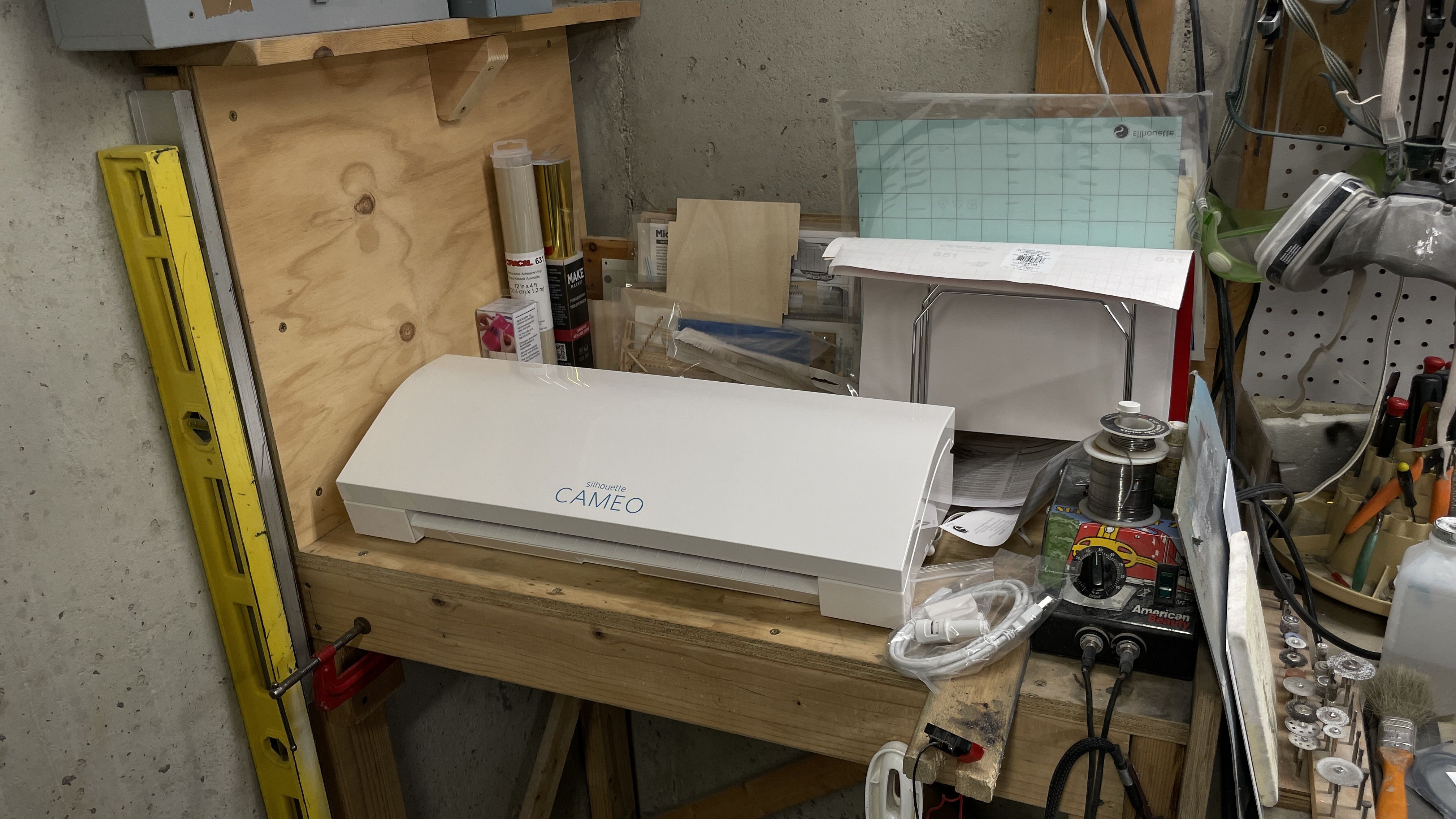
I sincerely hope that the fog of Tamiya Gloss White airbrush overspray is not toxic, because the basement was full of that stuff this afternoon. And I’m also glad that a) I wear “shop clothes”, b) I wear “shop shoes” and c) that it has a bare concrete floor with years of paint, etc. splatters all over it. I say this because, I was about to stir in some thinner in the last bit of gloss white paint I had, lost grip on the glass paint spray bottle and it hit the floor, broke and spilled that precious white paint all over the place. Anywhere and wearing anything else, that would have been a catastrophe. In this case it was just a pain the in the butt and a bit of a mess to clean up.

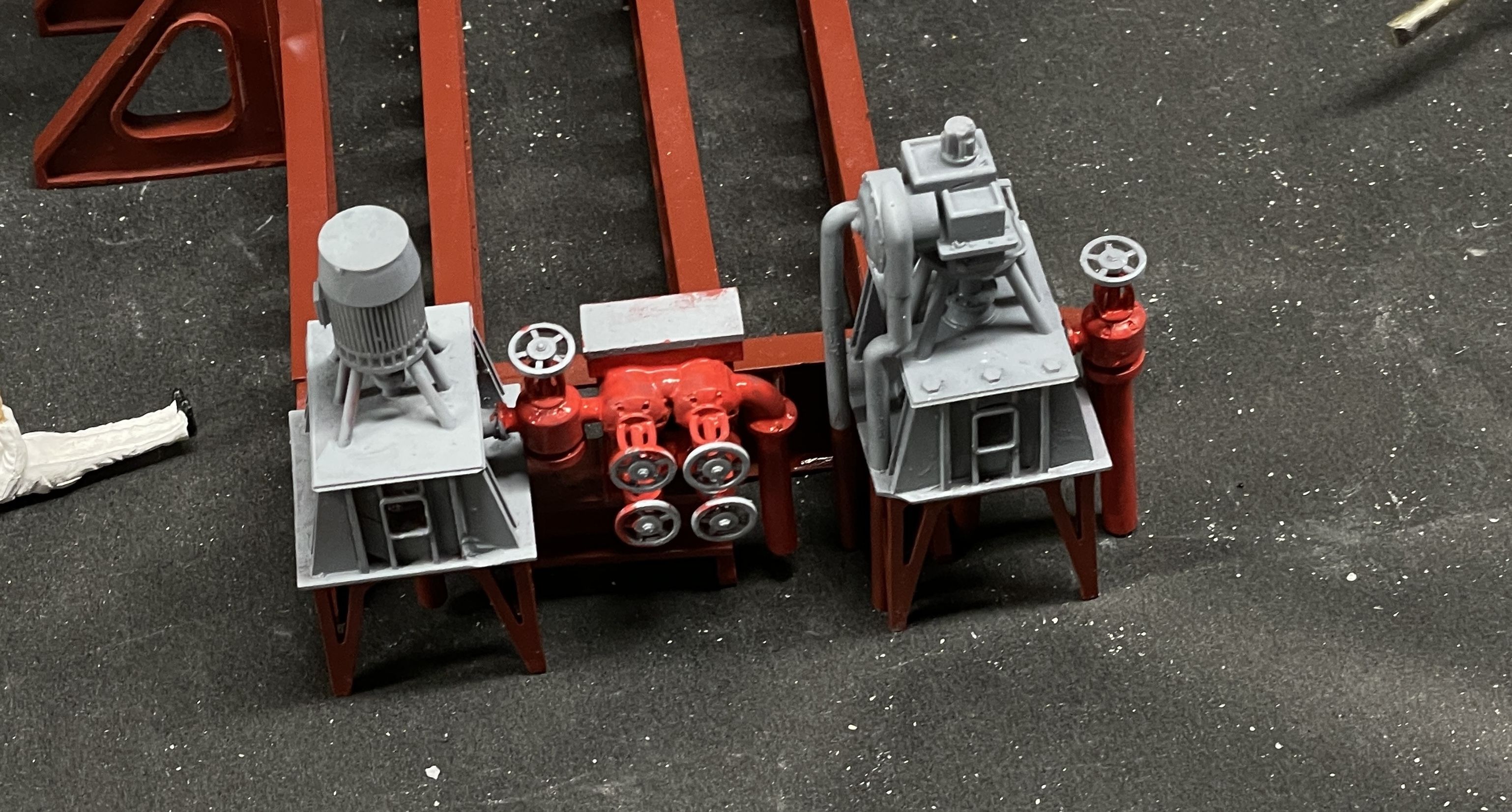
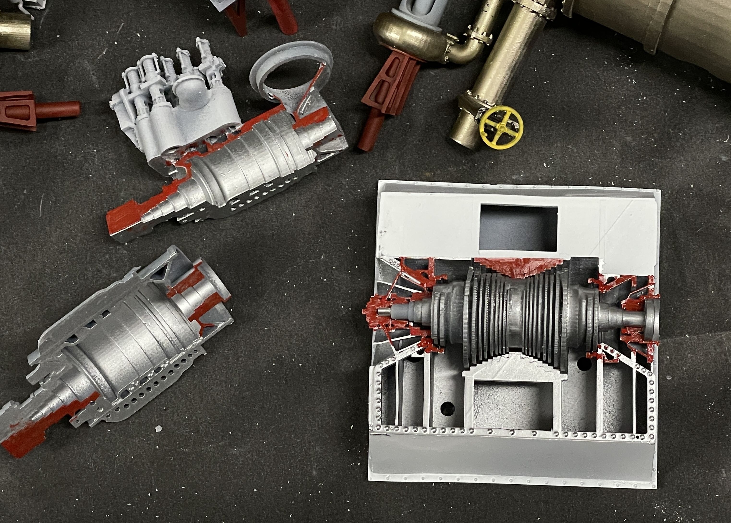
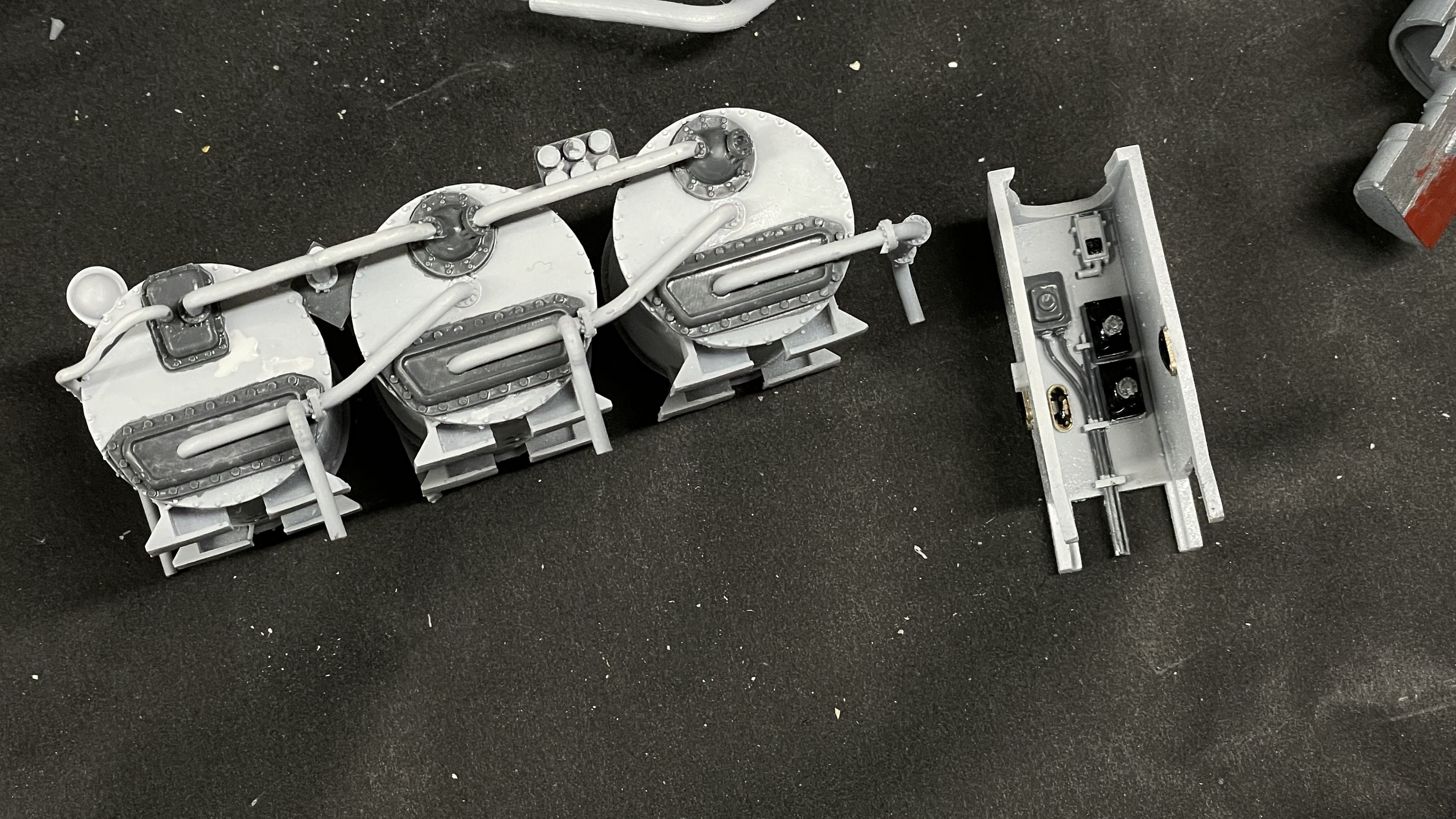
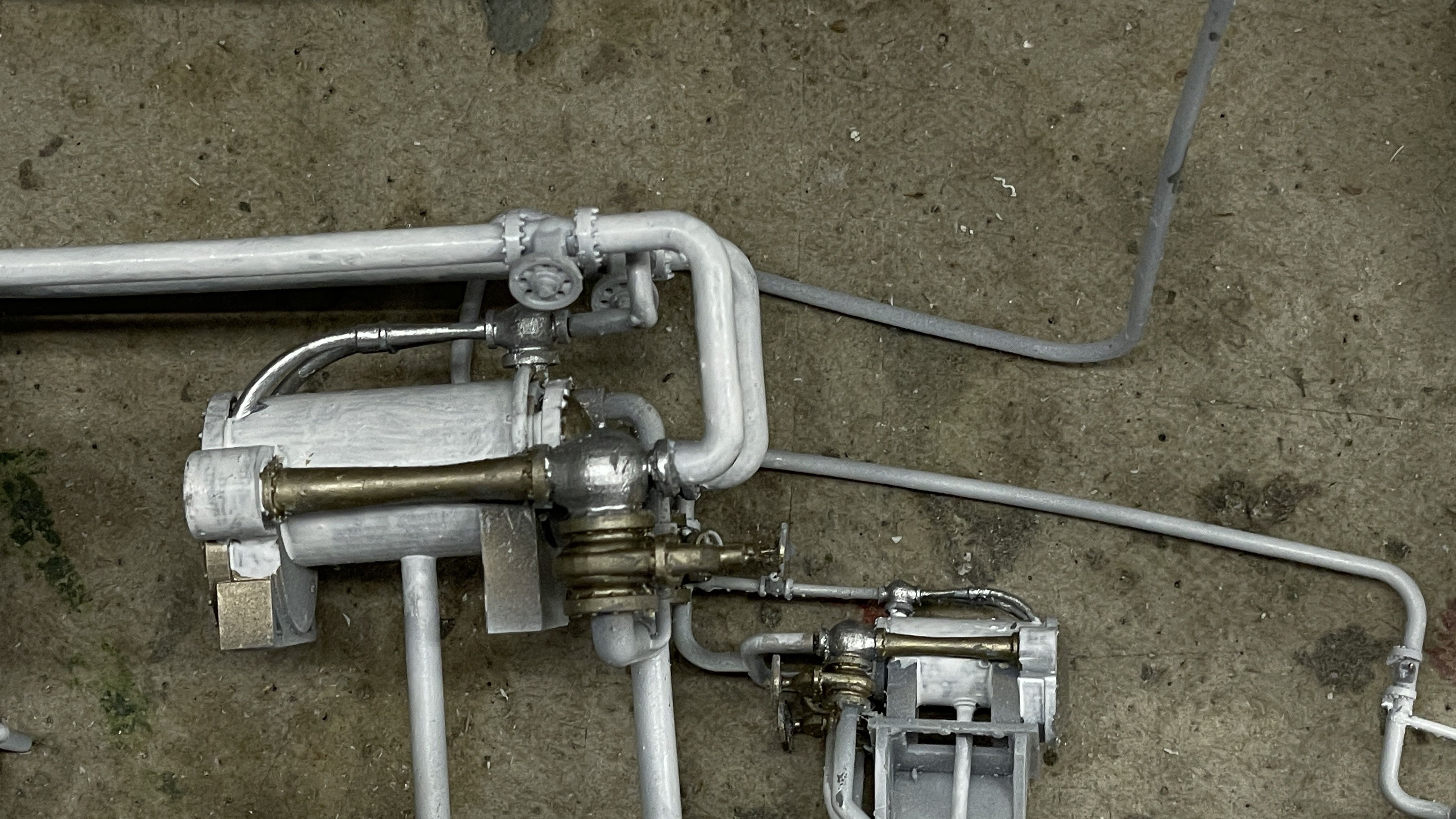
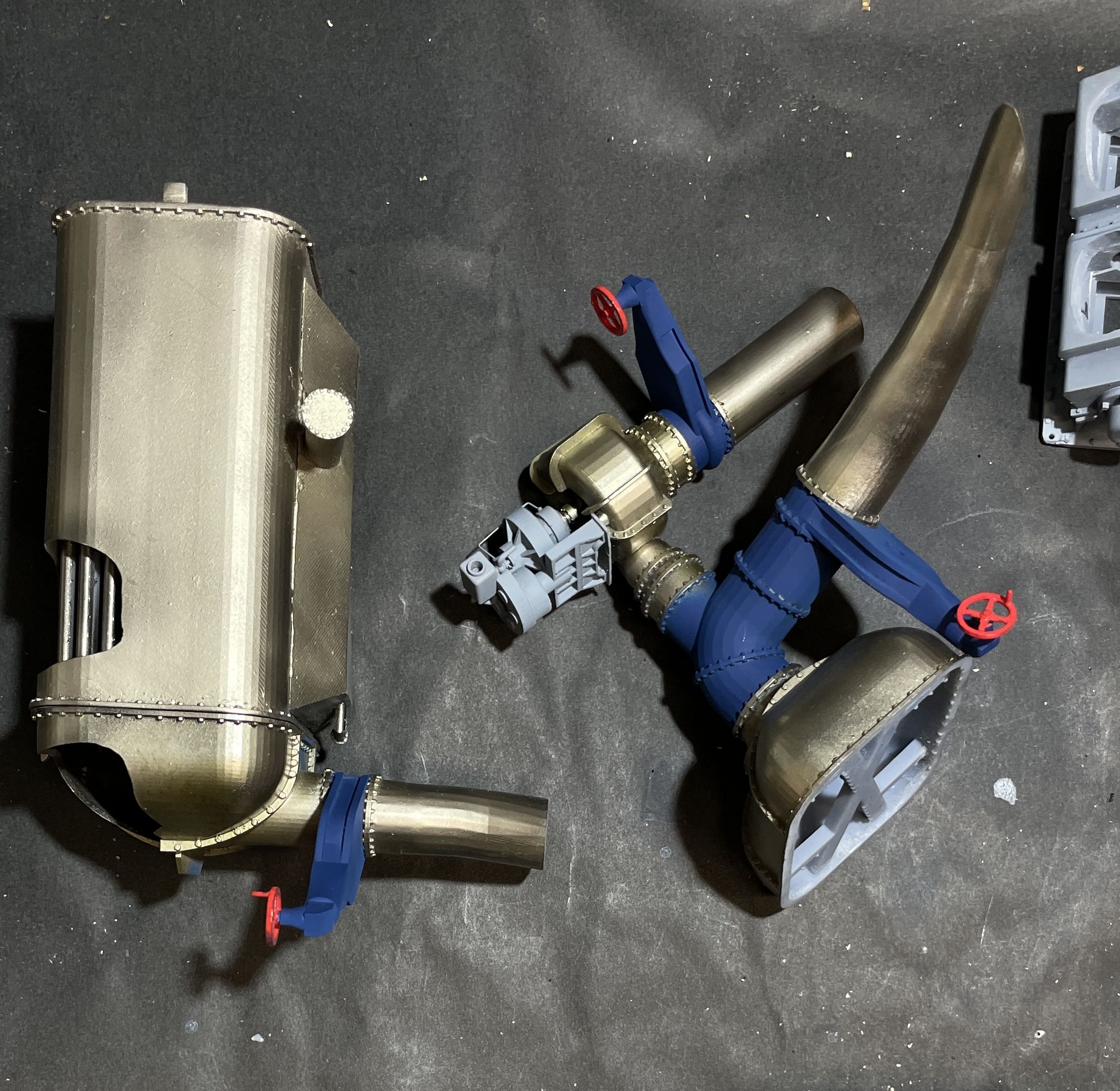
I finish painted all the bronze main condenser parts. I happy with the results. Part of the assembly can be glued together now, but one end needs to go on when I’m installing it on the base floor so the pipe can position properly.

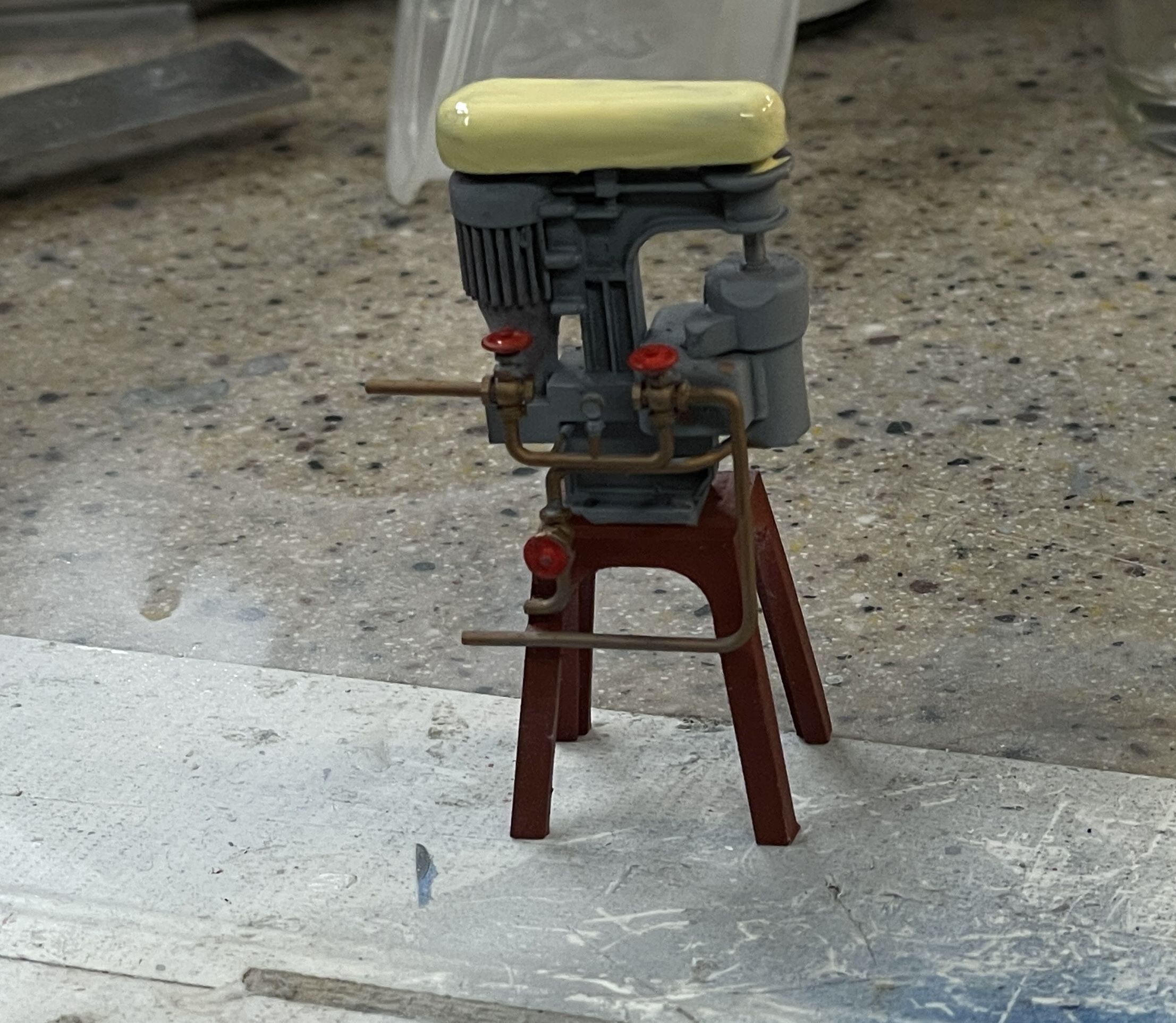
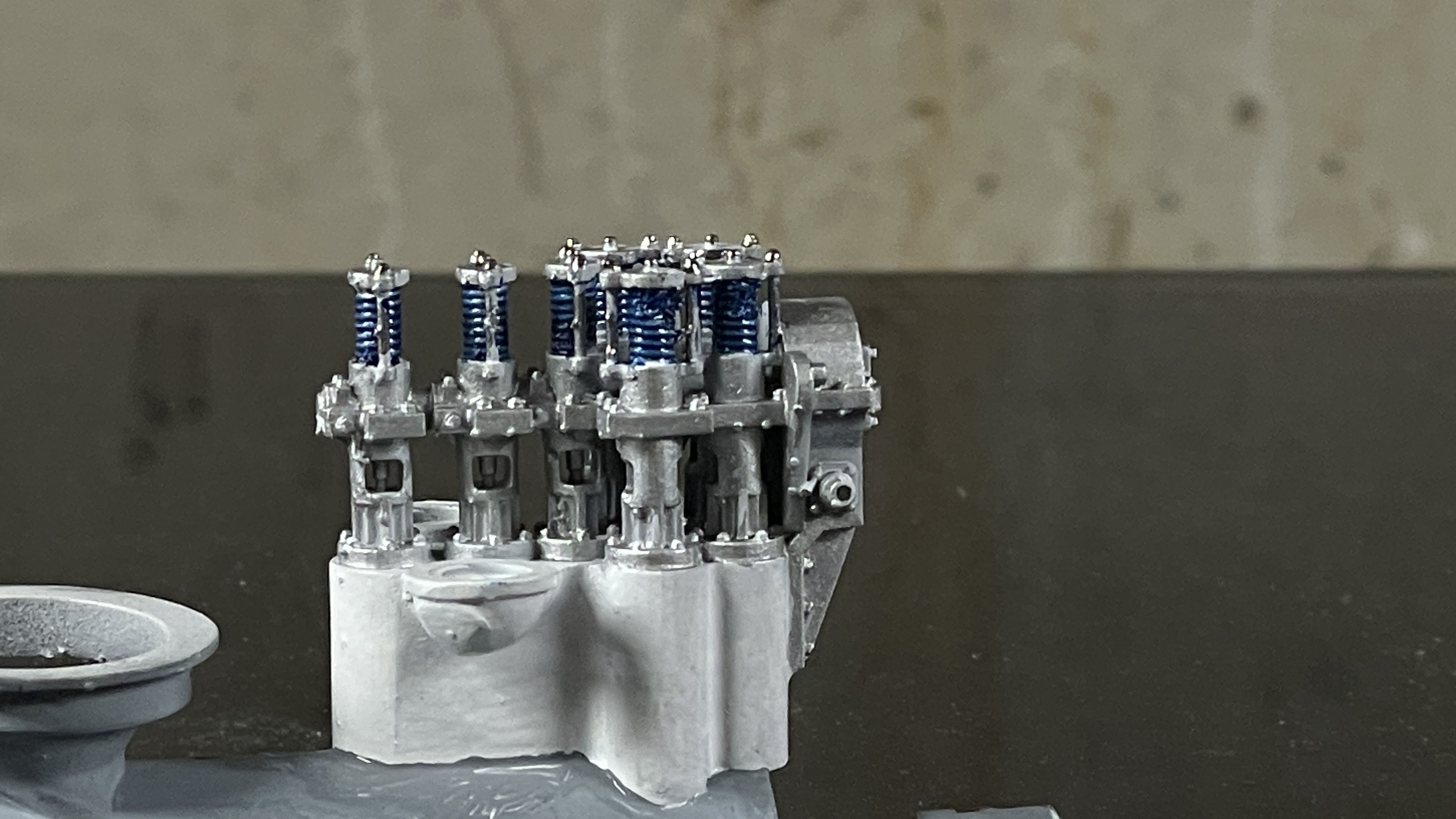
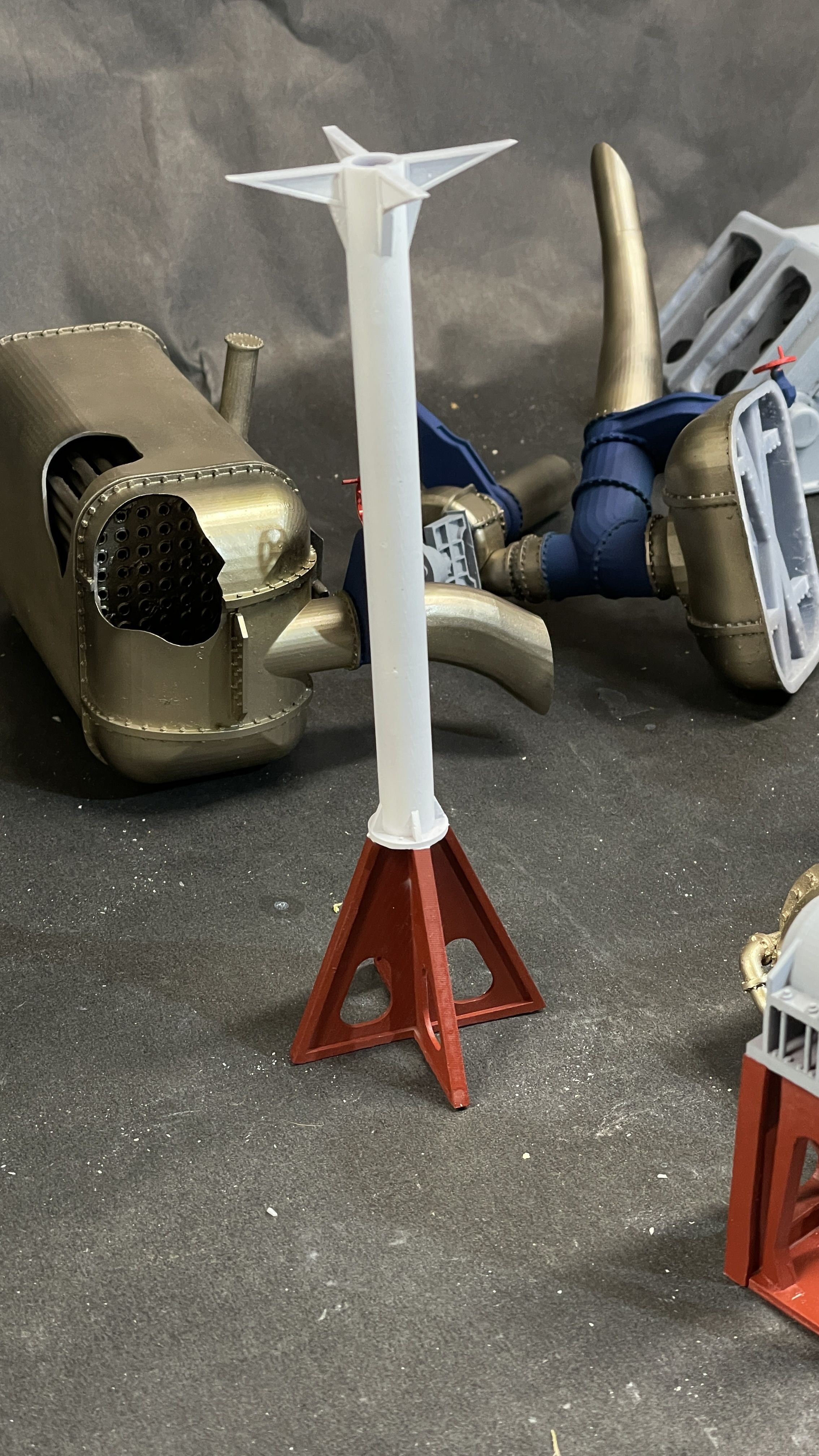
I finished the central column with a coat of gloss white on the upper parts. The paint ran out (read “spilled”) half way through painting the main steam header. I will be buying more paint tomorrow, and may get some time to use it. The entry hatch floor will be expoxied to the cross-supports on the top of this column. I limited the amount of paint on the gluing surfaces.

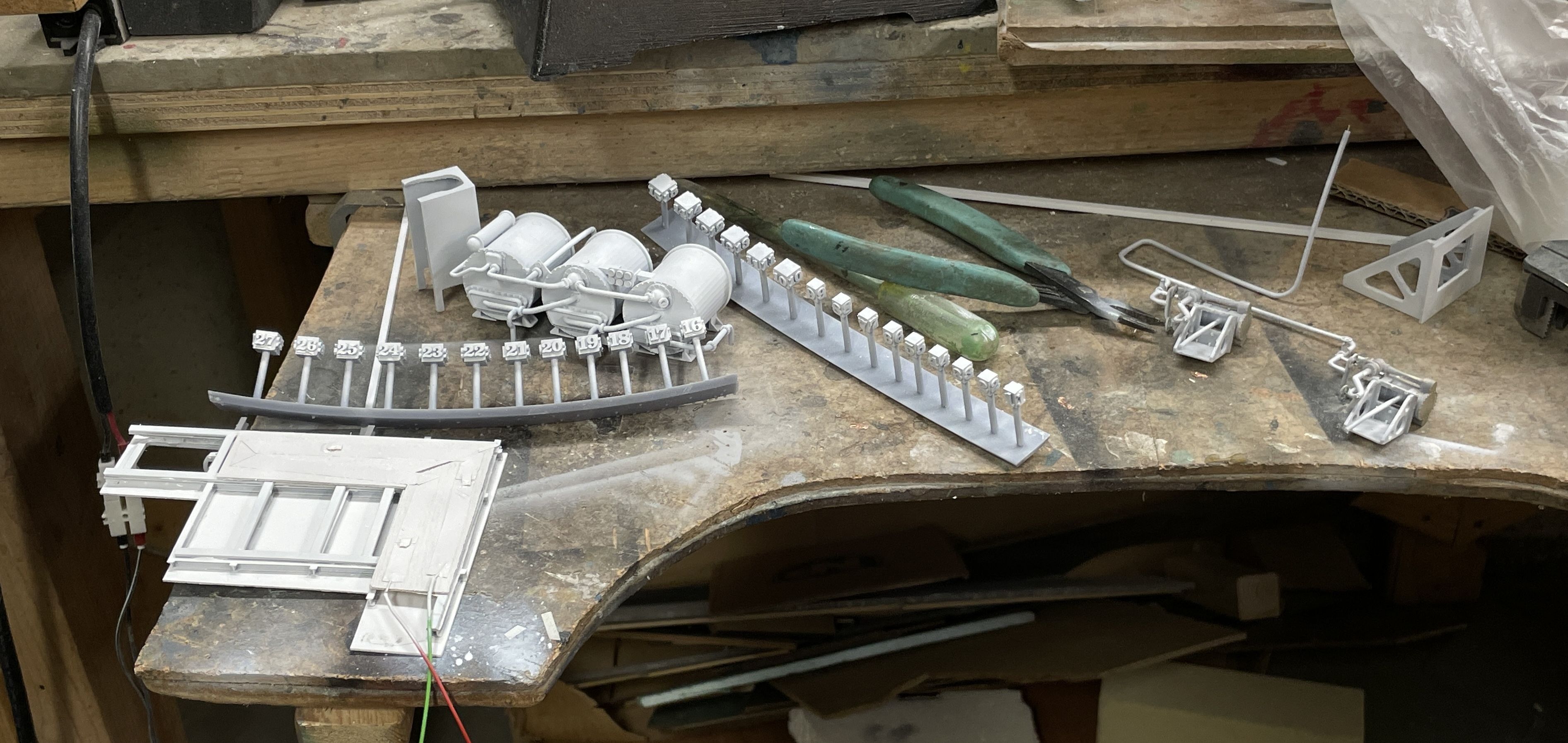
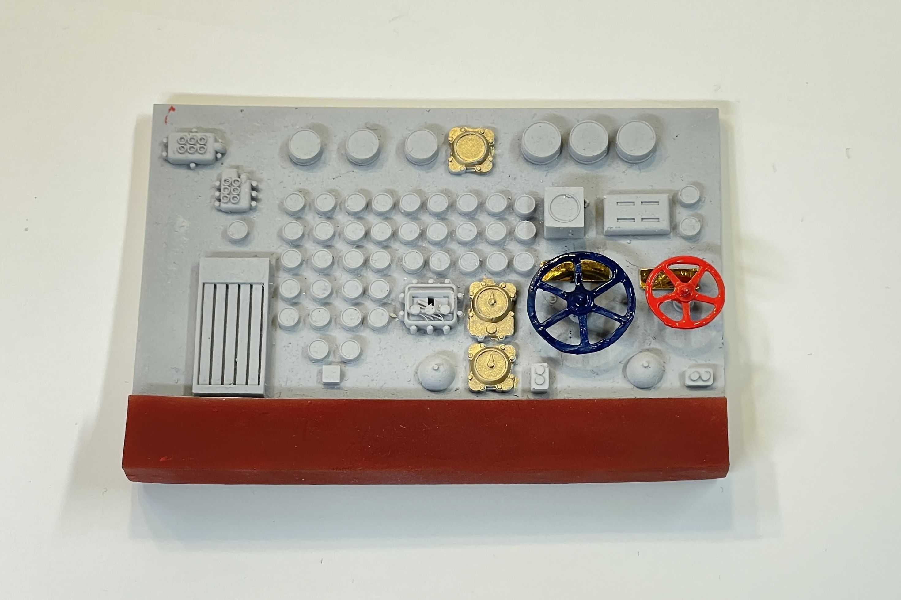
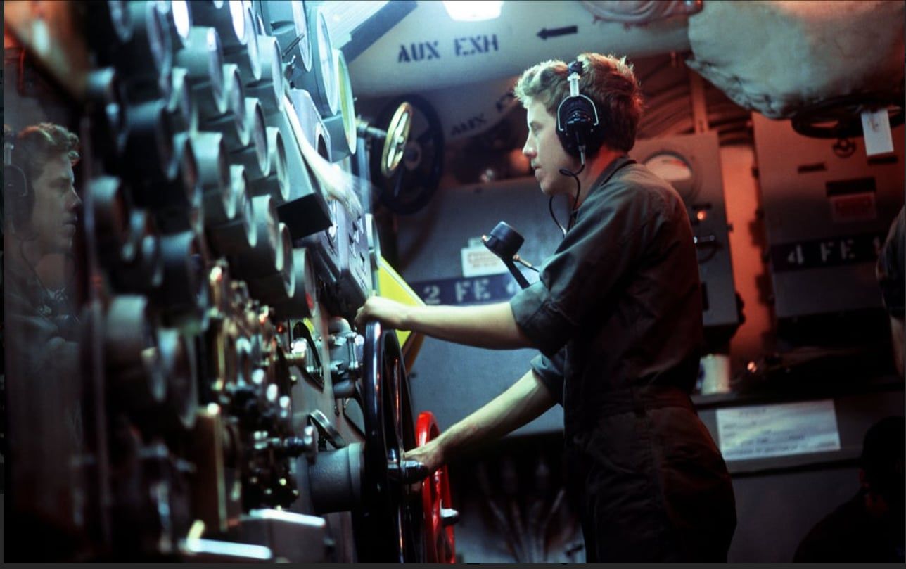
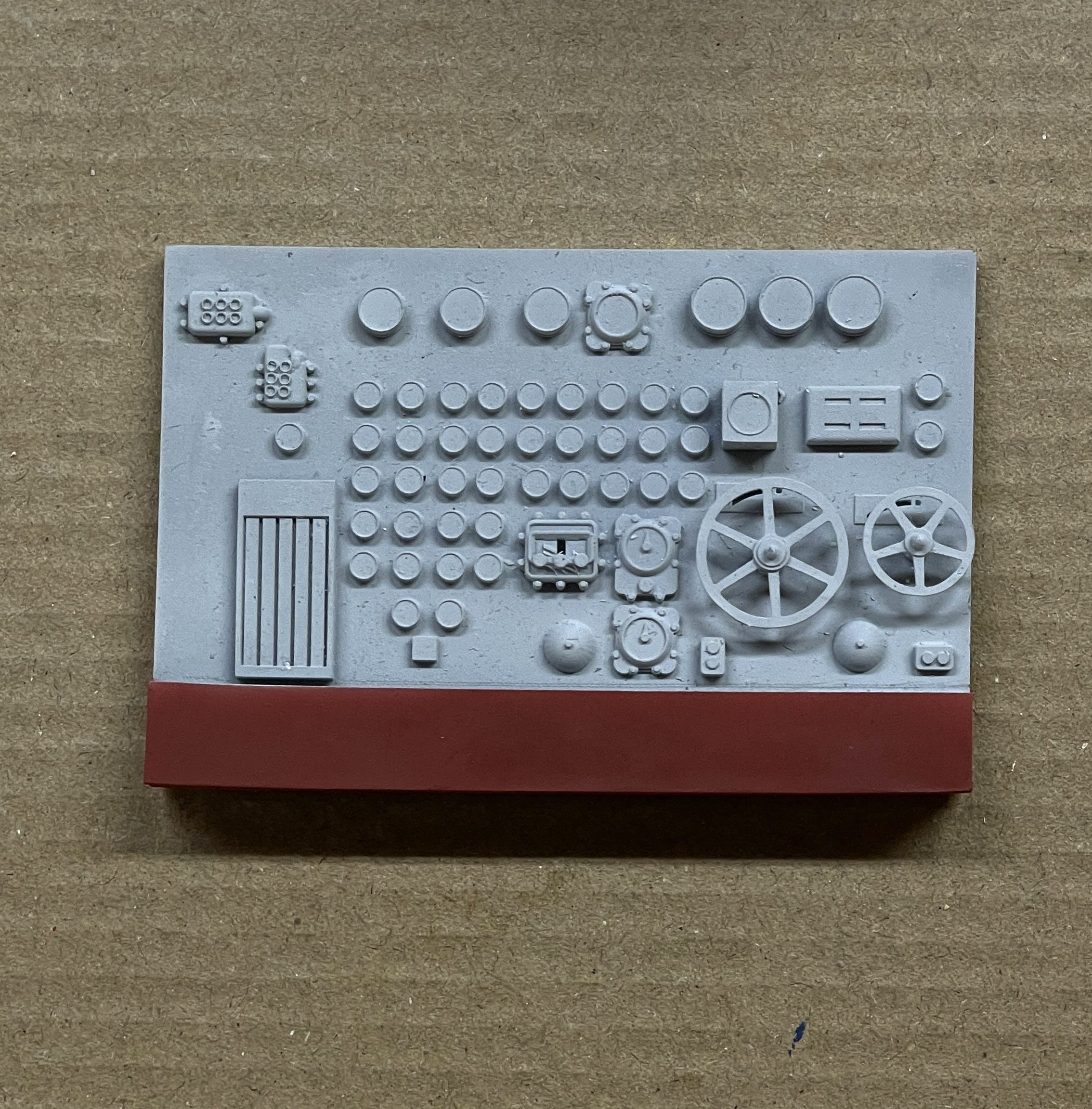
I got the red base painted on the main gauge panel. The next steps are picking out all the details. Not all of the gauges have the same colored bezels, so I will be using the pictures of the real on to do it as it appears in life.

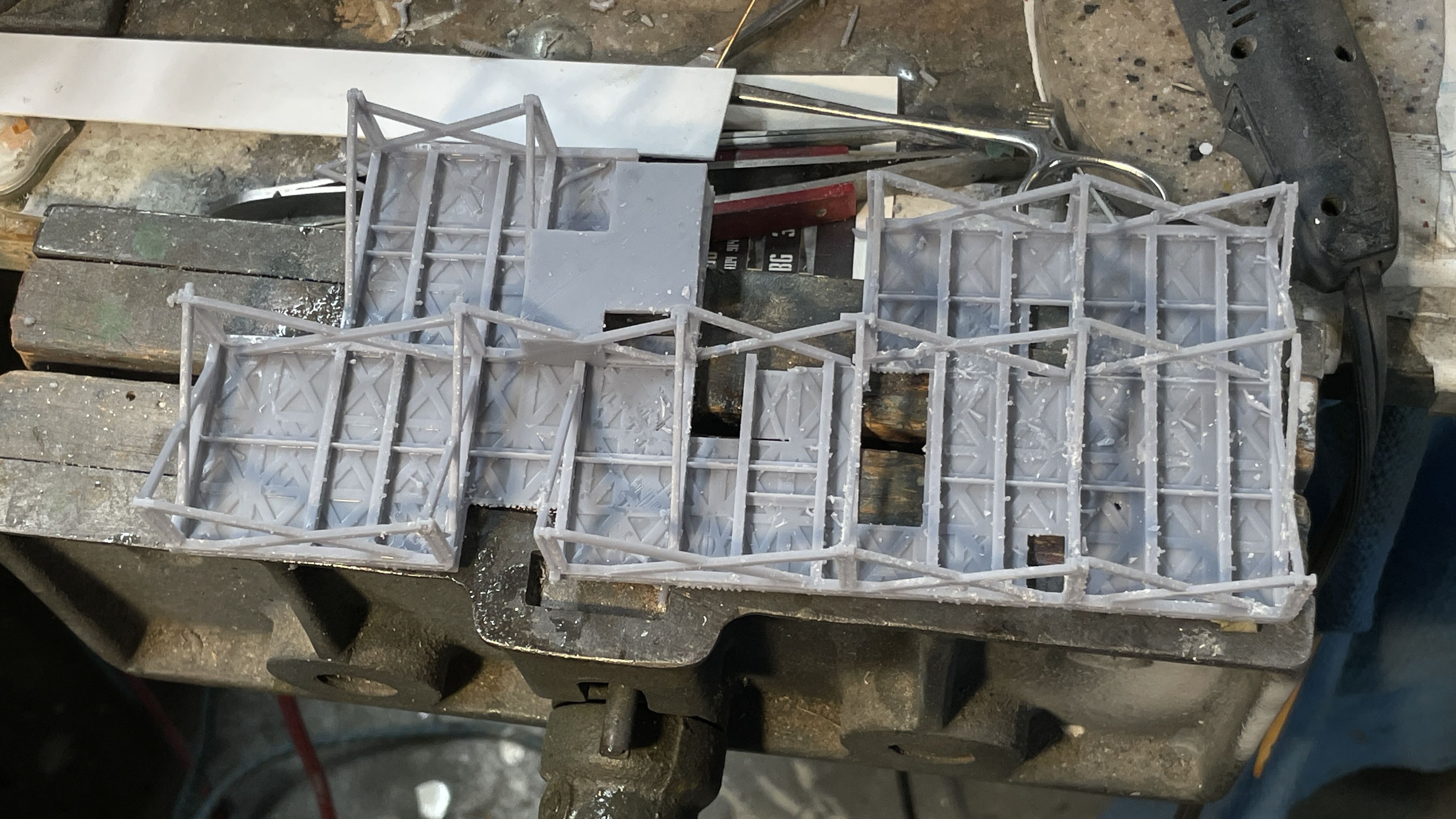
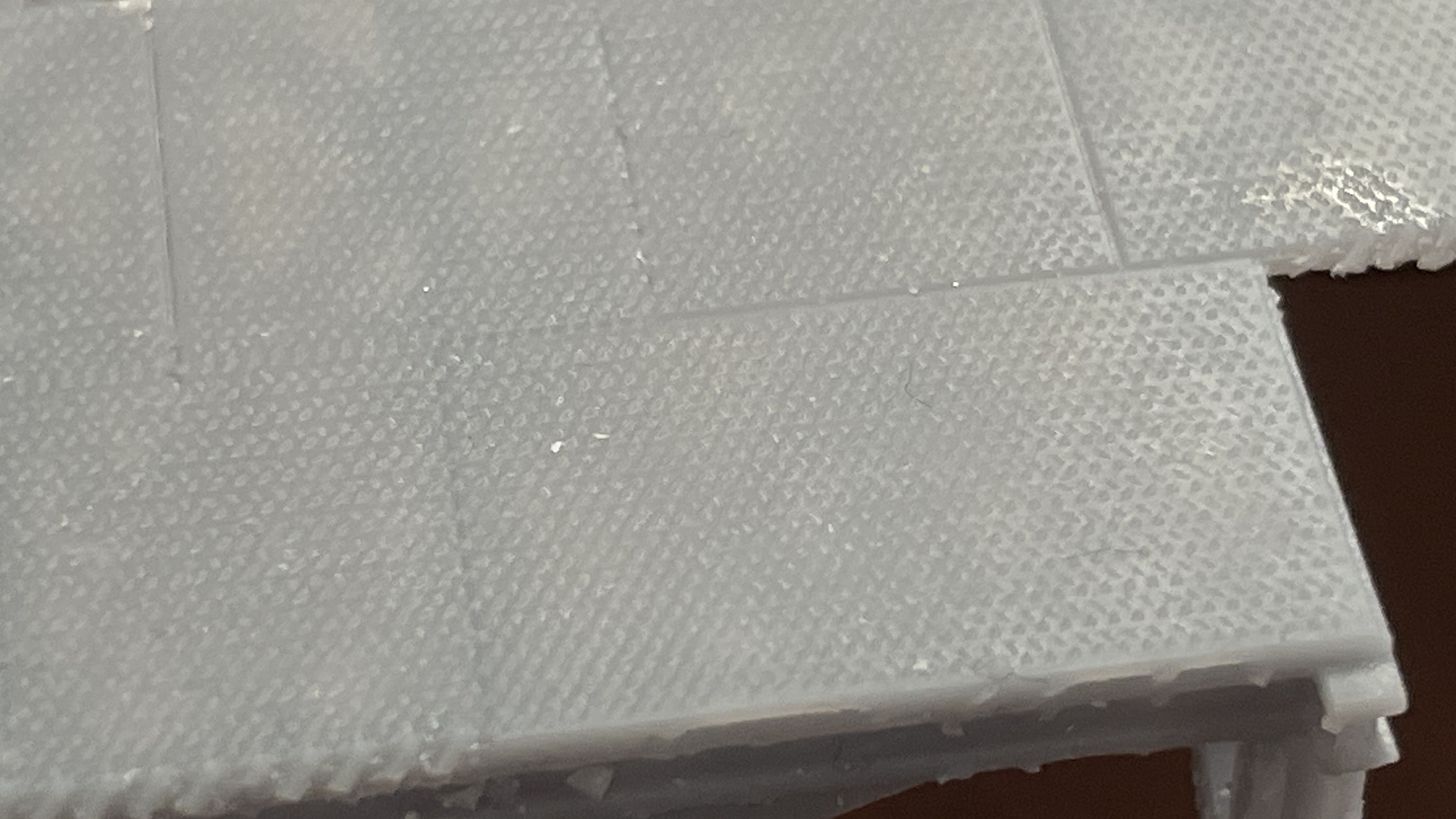
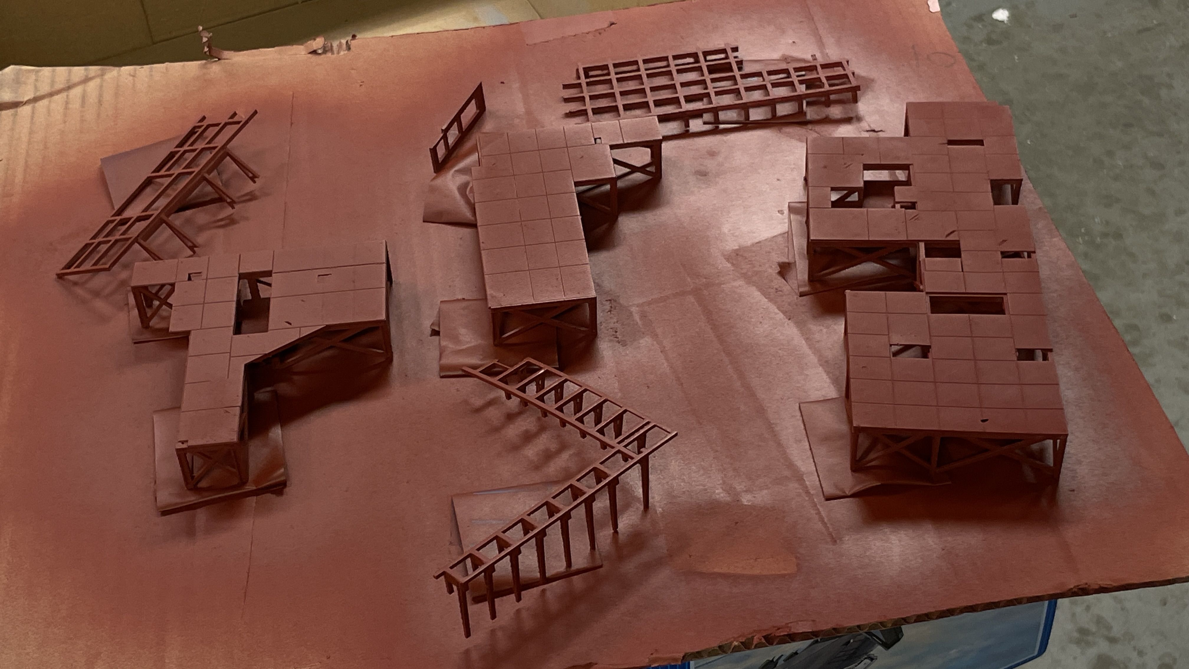
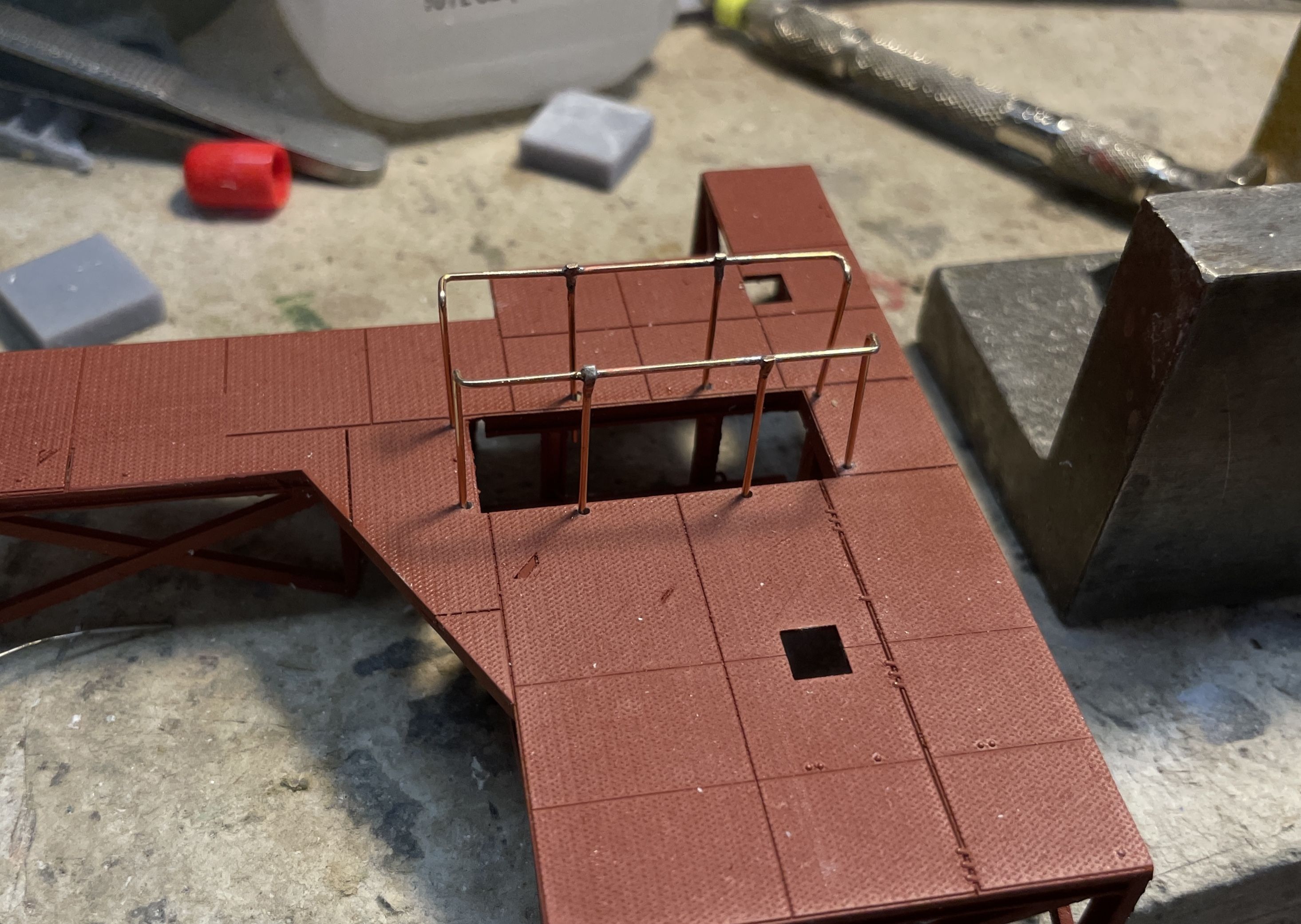
I am in the process of redesigning the entire 1st level floor system, making all the sub-frames as a single printed part. My original idea of having little 2’ X 4’ self-supporting frames was untenable and would be an installation nightmare. I drew a flat piece on top of the existing frames and intersected the faces to identify where all the apparatus penetrats the floor. I then took that pattern and rebuilt the floor system underneath it. All the myriad of legs are now cross-braced so they’ll be very stable.

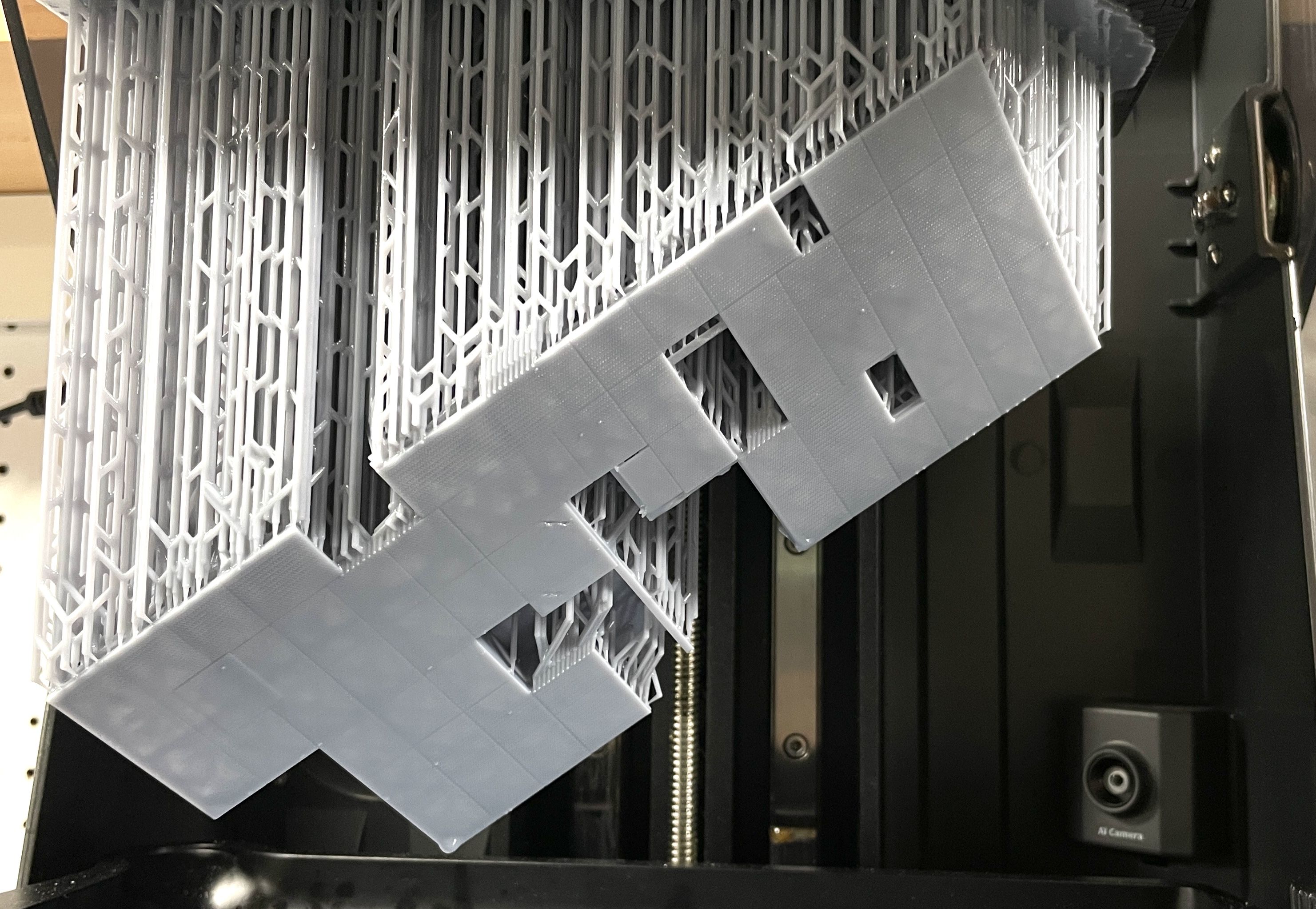
Here’s a sample of what I’ve done.

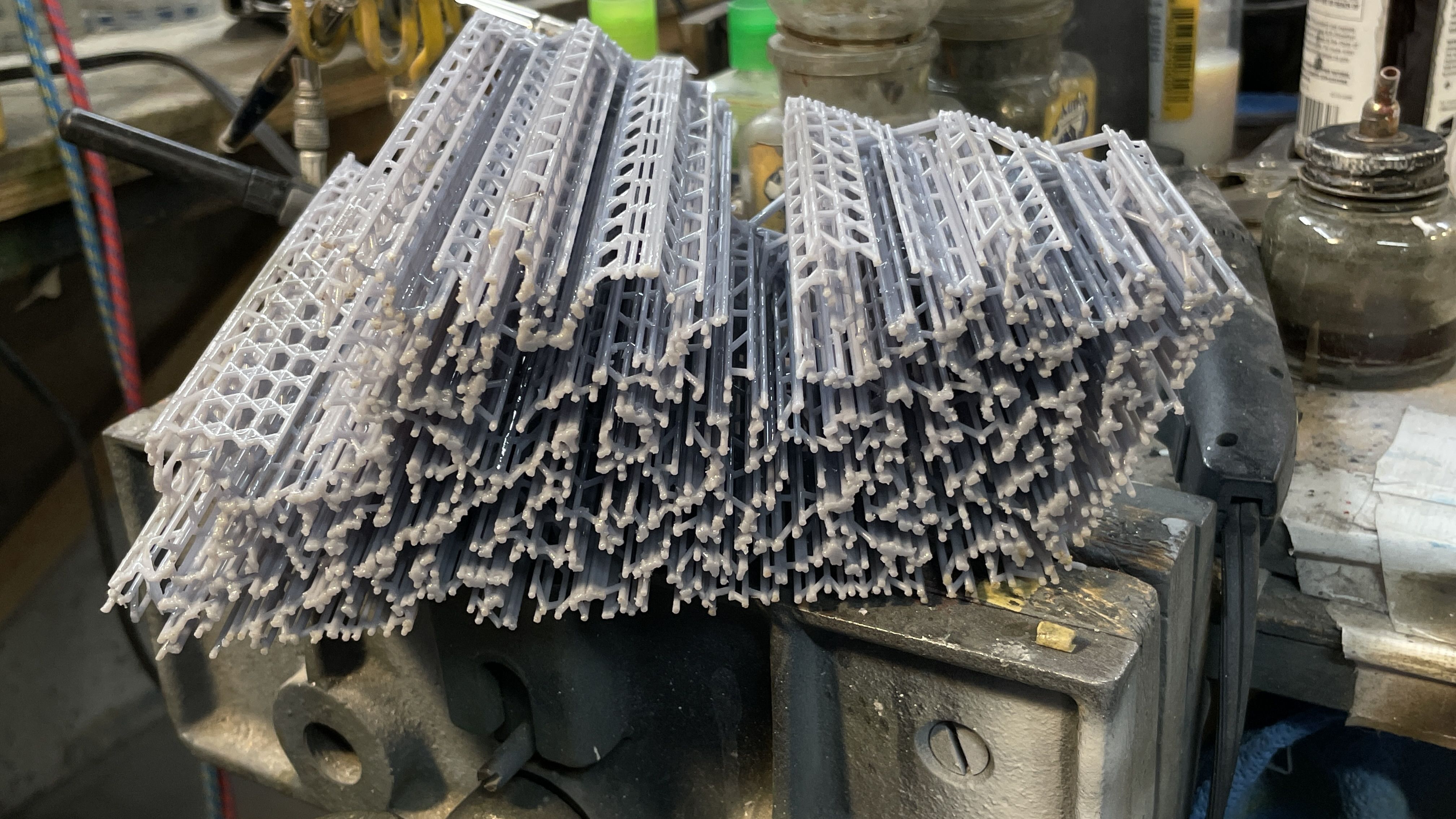
I have three of these systems; two are finished and printed and the 3rd is almost done drawings. The port side frames are split done the middle to facilitate installation. The starboard frames are a single and I will install the evaporator deck through this floor. Here are the first two out of the printer and cleaned, but not removed from the forrest of supports nor post-cured. I made sure that all the joints were in full contact with each other so there shouldn’t be any printer glitches.

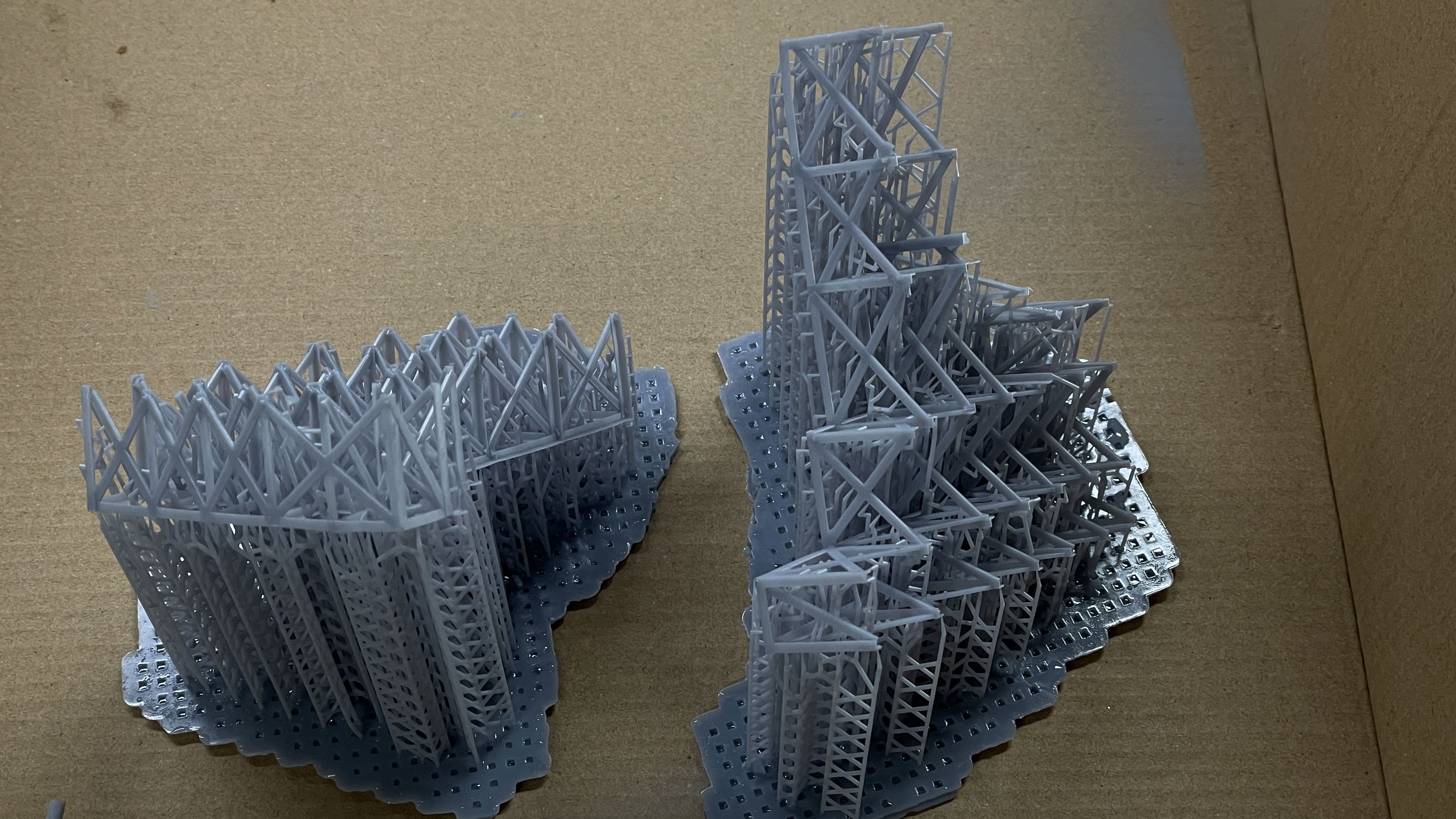
I love the the new printer can print objects this large as single printed object. Both of these were printed in one load.

I’ll have some work time tomorrow, but be gone for a little over a week for a trip back East. I probably won’t get to the battelship this trip. I don’t really have anything I need for this project any longer. Of course, I could always visit the ship… it truly enjoy it.

4 Likes

I didn’t have much time today after going to the hobby shop to replace the lost white paint, but that didn’t stop me from getting something done. I finished painting the white paint work including the escape trunk, piping around the air ejectors (small and large), and miscellaneous other stuff. Notice that I white painted the numbered studs that are going to go in each identified piece of apparatus in the final display. There are still many loose pipes that need white paint. I will get them later.

I detail painted the lube oil purifier.

The escape trunk and large air ejector white piping.

Notice painting the underside of the entry deck. The lighting circuits are now fully camoflaged. The upper surface will be linoleum brown. There’s gray detail painting on the evaporators needs to be done. I like detail painting. The small air ejectors are sitting there also.

The electrical tape on the main steam pipe that’s wrapped around the middle is almost invisible now that it’s well-coated with Tamiya gloss white (As planned).

Then I did the first coat on the red valve bodies on the lube oil pump manifolds. After finish painting the red, I will paint the top of the box-shaped thing insignia yellow with black warning stripes and the valve handles yellow.

​I painted the new electrical cabinets sky gray. I will pick out details later, hopefully without breaking any of those cute little hand knobs on the bottom.

Before I went upstairs I sprayed the insides of both the low and high pressure turbines Tamiya spray Silver Leaf.

We leave tomorrow for Philly. I won’t be going to the ship this trip. Nothing to learn. But I will be going back in the Fall to deliver the new model.

7 Likes

All those parts look great with your nice paint jobs.

Thanks Tom!

Got back from the trip on Monday, but didn’t get into the shop, per ce, until today. I was doing some design work and had some doctor’s appointments (follow-ups.). During the trip I did some re-thinking about the flooring system. I hadn’t even removed the supports from the last print of the port side flooring, but I wasn’t looking forward to several aspects of them. I didn’t think the angle iron framing was going to work well for gluing to the base. Additionally, I wasn’t looking forward to gluing the individual diamond-plate segments onto this deleicate frame. Lastly, I had way too many supports under it. It would be out of view and just complicated cleaning up the print. The re-design entailed, using H-Beam structures for most of the frame, reducing their number by 2/3 and then installing all the flooring plates and printing it as a single, integrated unit. I didn’t know if it would print well, but as usual the printer came through. Here it is hanging on the printer after finishing tonight. There is a vast amount of supports to remove because I chose to print with the delicate diamond plate pattern. Support debris would destroy thosse details, but required more supports becausse of all the cross-bracing below that was lying horizontally to the build plate. Horizontally aligned surfaces always need lots of support since the resin doesn’t bridge across horizontal surfaces only for short distances.

The floor is nice and flat. All the openings are for lube oil purifier, prop bearing pedestal and columns supporting the evaporator foundation.

Here’s the drawing showing the revised under structure. Compare this to the previous design on the port side floors. With this print success I’m going to revise the others to do them the same way. The heavier H-beam legs gives more substantial gluing surface.

Trimming, cleaning and painting will happen over the next few days. Tomorrow is the 4th of July when the USA became a free democracy and I may not be working in the shop. We’re not going anywhere, so who knows…

While the printer started working, I did the first round of painting the little callout sticks that I’m contemplating adorning all the pieces of interest to conform to the printed key. There’s a few spots that need to be touched up. I was more difficult painting the numbers that lay between the sticks.

I’m now looking to expand my shop’s capability. First, I was told that you can use a 5 gallon paint pail filled partially with water as a means to capture and filter out fumes from a small paint booth. My favorite hobby shop owner told me that one of our club members has been using this method for years with good succees. The only reason I didn’t get a booth was the outside venting it would require. This method solves that problem. I viewed a video of how to do it and it’s quite easy and I happen to have some of those paint buckets lying around. I’m going to buy myself a paint booth for my 80th birthday that’s the 30th of this month.

Next, I was also told by one of our club members that you can effectively use a digital vinyl cutter to make painting masks and other items for model building. They’re not just for crafting… I started exploring this and knew that my very talented and techie daughter in law had one. On our trip we stopped at my son’s house in State College PA on our way back from Philly to Louisville. I only wanted to ask her about purchasing advice. Instead, she gave me a spare, brand-new, Sihoulette Cameo 3. Yesterday I bought some materials at Michael’s and am reviewing how these things work. I have some uses for it for the engine room project. I’ll you informed.

5 Likes

Worked on the model yesterday and today and am making 2 steps forward and one back. When I tried to assemble the new floor with the lube purifier that must penetrate through it, I couldn’t install it since the valves and plumbing wouldn’t fit through the rectagular opening. I then dropped the unit on the floor breaking it in half at the base junction. Instead of being annoyed, it answered the question of what to do next. Next was re-drawing it as two parts and ending the piping at the floor diamond plate level since you won’t see any of it underneath anyway. So that’s slated for printing tomorrow.

I also found out that the duck under cutout and floor are in the wrong place (about .75" too far aft (19mm). I also forgot to open one relief hole for one of the evaporator deck columns that must pass through. Furthermore; I set the job up in the printer with the front facing edges getting most of the supports. Even after cleaning and sanding it looks a bit ragged. So I’m re-designing and re-printing the part to solve all of these issues.

I thought it would be interesting for my followers to see just how many supports were on this piece of flooring. it took more than a half hour to get rid of them. I sawed off the base which made it a little easier to get into the morass and cut them loose, but here’s what it looked like after the raft was removed. When I reprint, I’m going to adjust the density setting. I don’t think the job required that many.

The bottom of the part after support removal.

And what was in the trash can. Uses a lot of resin. I amd sure there was more resin consumed in the supports than the part itself.

I had to be careful in not using too much brute force. Sometimes the cross-linking from one support to another capture some of the model such as the cross-bracing on the legs. Pulling the supports off without tracing their path can lead to ripping the part itself in the process.

​This shows how much off the duck under is. It also puts one of the support columns into the duck under instead of next to it.

Yesterday I started masking the base for the white paint. I had to stop since I’m going to added some I-beam supports on the bulkhead where the entry hatch and deck are being installed. Wanted to paint the white with the decks in place, but can’t glue them in yet. I’m going to notch the deck to install them over the I-beams.

The diamond plate pattern shows up nicely under magnification. It’s small, but it’s there.

The port side forward floor assembly printed well and I fit the ladders into the duck under to see how they fit. i needed to thin the ladder’s sides to gt the fit right.

Trim painting continued with picking out valve handles, and painting the cutaway areas. To do that red paint I used a Testor’s paint marker. Easier to control than a brush.

And I continued working on the main gauge panel. The bright brass behind the throttle wheels is metal vinyl that I’m going to use for this purpose with the new vinyl cutter. I didn’t use that cutter for this since I don’t know how to work it yet. A lot more work to do on this before it’s done.

The vinyl cutter now has a place on my work bench system.

I had a load of stuff in this spot and nohwere to put it. There was a spot in my storeroom that was occupied by too large boxes of sprues left over from many plastic kits built by me and the grandkids. I don’t know why I saved it, but had used any of it. So it all went to trash and there was space for all the bottles and spools of wire.

I wrote a note to Reskit asking if they had any figures I could use to populate the engine room. They are a really neat Ukranian after-market supplier of highly detailed cast resin (and now 3D printed) detail parts. I used them on my award winning Sikorsky Seahawk. They wrote back today saying they were really happy with my project and will look into this. He asked me to describe the clothing worn in the engine room, and I reached out to Ryan. He sent me three images today showing their garb and I forwarded this to Igor. The fact that Ukranian companies like Reskit and ICM are able to continue working during this miserable war is remarkable. I noticed in this image that that the throttles have nice chrome acorn nuts holding them on. I will add that.

5 Likes

Painted pipes today, and continued picking out the small details. Got the third floor system printed and post-cured, and redrew the first one and it’s going to be printed tomorrow.

As I noted on my last post, the supports had some wrap-around which pulled one of the legs and cross-bracing off in the cleaning process. I’ve often said that removing supports is the #1 failure mode of 3D prints, especially when they’re as complex as some of these are. Since I was scraping the first one printed, I was able to scavenge some pieces to graft them to this, otherwise perfect, floor system.

More to come tomorrow. Please ignore the slight size difference of the front portion between the two sides. When installed, it will not be noticeable and I didn’t want to reprint just to fix that.

3 Likes

Painting continues and is almost done. If I get a good, long session tomorrow I could get it all done. We had a break in all the thunder storms and I got the base red done on all the decks and deck supports. I have a couple more red parts to paint, but probably won’t have to do it outside. On the right is the newly-printed main floor replacement.

I detail painted the HP throttles. There’s some painting to do on the upper quandrant of the LP turbine, a few tiny details on the turbo-generators and painting the replacement lube purifier. There’s some touch up work on the various air ejectors, but that’s all minor stuff. Once all this is done, the last painting is the white bulkheads. When that is done equipment placement will begin sometimg this week. The throttle springs are molotow chrome base with Tamiya clear blue overcoat.

All the railing I have to solder are 32" high. Instead of soldering a retainer at the bottom to hold the correct depth, I drew and 3D printed a bunch of scale 32" spacers that I will use to set all the railings at the same height during gluing. The little frame next to my power sander is the last catwalk support for the very narrow grated walkway between the HP and LP turbines. I think it’s the last support piece I need to design and print.

5 Likes

Detail painting continues…

The turbo-generators are for all intents and purposes are finished painted. There may be a touchup or two I have to do, but they’re done. I had to replace one of those vertical guard poles with wire when one broke off at some point. 600 pound steam lines connect to those two valve bodies. The “copper” color was created by a chrome cylinder base covered with a mix of Tamiya Clear Red and Clear Yellow in an imprecise ratio.

The main and aux air ejectors are also just about finish painted. I hate brush painting white paint!!! Valve handles need painting/replacing where missing.

And, except for some very minor touchup, the main gauge panel is done. Wish I could have done decals for the gauge faces, but inkjet decals just don’t work in this size.

Here’s the composite photo I used to paint it.

5 Likes

Today I’m started making some strategic inroads into assembly. Not actual assembly, but more like “assembly prep.” What follows is a bit arcane so please follow closely.

​All that’s left to paint is the fore and aft “swiss cheese” bulkheads. Before painting I had to install the inside support beams that would hold up the aft end of the entry level floor. To measure the placement for these pieces I had to have the entry floor epoxied to the main support column which, in my rendition, is what’s holding up the fore end of the entry floor structure. In the real ship, the entry floor is supported by the entire third deck’s flooring system, which is missing on my model. After epoxying these two sub-assemblies together, I had to place all the necessary equipment on the hold floor so I would get an accurate placement. While doing that I attempted to fit the large crew floor piece that I made yesterday, and found that it interfered with the starboard main reduction gear angle brackets. I made quick work of creating relief cuts so it would snuggle to the correct spot.

I suspected I would find other interference areas and didn’t have to wait long. When I put the central column into place next to the MRG’s frame, the column’s aft triangular bottom brace brace crashed into the electric lube oil pumps foundation. In this case, it was easier to hack away at the column base than to surgically alter the pump since it was part of a larger structure and would have been more troublesome to modify.

Before epoxying the column to the entry floor system I had to be darn sure that I was putting it in the correct location. This took some trial and error get the positioning right. I’m using 5 minute epoxy and glad I did. I had to hand-hold the two parts in alignment until it set up enough to sefl-support when placed on the table top to finish cure. The relief cut is pretty obvious.

After I was able to locate and mark the height and lateral location of the support frames, I cut them from some scrap Plastruct I-beam I had left over from a previous project from years ago. I cut some cross pieces that needed to be notched so they nested into the verticals. I glued them together with solvent cement. Plastruct parts are ABS plastic. I then positioned the frame onto the bulkhead to recheck its positioning.

The trial fit has the floor at the very top of the bulkhead wall, which is actually correct.

I got worried that it may impinge with the aft MRG frame and did a quick check and found that there did clear, albeit closely. When the gear box is place there still may be some interference, but I make it work.

In this case I used rubber-infused CA to glue the frame to the styrene wall. Again I needed to make sure that the hold floor would be able to slip underneath the supports before gluing. I was able to slipit underneath. With that last check, I was able to glue it in place and clamp until cured. This newer CA product needs 15 seconds to cure so I was able to adjust plumb.

​To do the bulkhead painting I needed to mask all the oxide red parts including the hold floors. This morning I awoke realizing that with the floors not being glued in yet, I could easily substitute carboard for the real floors, and do the painting without worrying about them. I still have to mask the exterior areas, which I had already started. tomorrow, I should finish masking, paint the bulkheads and we’ll be ready to start fastening things to the real floors.

I was doing finish painting on the low pressure turbine, and knew all along that there was something funny about the fit, but left it go until later. Today was that “later” time, and I needed to do some router surgery. Don’t know why the rotor fit into the lower half, but the upper quadrant wouldn’t get close to fitting. I had to remove a lot of stock from the bearing portion that separates the low pressure and astern turbine wheels. Once I did the surgery, the parts fit and can be permanently assembled.

​Onwards and upwards!

5 Likes

​Finished masking the base, took it outside and sprayed it with Tamiya White Primer. When it was dry (it drys fast) I brougt it inside and sprayed a second coat of Tamiya Gloss White. After pulling the tape I found some erros and areas where overspray got behind the mask and touched up with Oxide Red and the white where necessary.

I then noted the locations of all the inner structure on the card stock that I used to mask the inside and made a grid that I could use to locate all the penetrations for the LED wiring that needed to pass through the ship’s base and through the wood base.

I placed the critical pieces on the card stock and noted where the holes should go so they would clear any of the internal structure. I found, to my annoyance, that I still missed the correct openings on the integrated floor prints. I’m not going to reprint. I will repair them so they’ll work. I still have to pay attention where the base “concrete” blocks will go. I can drill though them if they’re in the way, but would choose not to. I have to remove a square notch in the aft, starboard side of the electrical mezannine frames to accept the escape trunk. I already made accommodations for the trunk on the stepped-down walkway frame.

The image shows one location: the leads coming from the evaporator frame. It was gratifying that the main steam pipe wrapped around the central column as I designed and the entry floor was still able to align well with the wall.

Happy Friday. Work resumes on Monday.

5 Likes

These sessions don’t produce a lot of drama, but they’re essential. I’m basically doing assembly prep… that is… getting everything ready to actually assemble this beast. This includes things like re-printing the main gauge panel platform, painting the mezzanine walkway to conform to the red color I’m using on the rest of the model, painting a lot of grating prints in prep to install them, painting the re-printed lube oil purifier, cutting the clearances to install the escape trunk and opening the main gauge panel frame to accept the lube oil settling tank. I also isolated and 2D printed out views of the SketchUp master drawing to refresn my memory of where all this stuff actually goes. I have a lot of piping that has very specific locatiions and the drawings show what goes where.

The mezzanine decks needs a corner cut out to accept the escape trunk. I could have re-printed both mezzanine decks with the cut out buiit in, but since it took a lot of resin, and it seemed feasible to alter the part after print, I chose the latter. I marked where it would go and use an abrasive cutoff saw with the Dremel to remove the corner. Since cured UV resin is not a thermoplastic, it does not melt when you abrasive cut it. I had already re-designed the walkway and lower floor system to accommodate the trunk. I will put some trim to close up that gap between the trunk and the upper mezzanine.

I repainted the cut area and it looks good.

I used a plan view of the starboard side to determine the placement of the lube oil settling tank. I also drilled the bottom with two holes of a #30 drill to accept some solid core solder of the same size that will serve as the inlet and outlet to this tank. I have no idea of where these pipes will go, so I’ll use some modeler’s license to send them somewhare under the flooring system and let them disappear into the darkness. Using solder enables me to do some “field modifications” to determine their routing.

Lastly, I stuck all fhose wonderful floor greating prints to cardboard with some blue tape and airbrushed them all with semi-gloss black. I think I may have enough to do the job, but if I need more I’ll just print them. Ah… the joys of 3D printing your own parts. I thought these parts that would be floorinng red, but they are painted black in photos I have. So… black it is.

I’m hand painting the replacement lube oil purifier print. If you recall, I have to re-print them as a two-part affair (base and unit) so I could install it. It’s way underneath the flooing, but there will be lighting.

I’m itching to get started soldering the railings. It’s an essential detail that really makes a model pope. This scale is way to big for photo-etched rails and demands real, honest-to-goodness soldered railings. I’m also ready to layout and drill the flooring to accept all the light wiring and penetrating piping. And then assembly will begin.

5 Likes

Things are moving right along…

I needed to add piping under the lube oil settling tank. For this I simply used some appropriately-sized solder wire. I polished the solder with steel wool and then used a mix of Tamiya Clear Red and Clear Yellow (mostly yellow) and airbrushed the mix directly on the polished metal, and Voila… copper!

These pipes will be bent to go somewhare, but I’m not sure where that is at this time. That’s why solder was the best choice because it’s very bendy.

I cut the framing of the main gauge panel floor to accept the oil tank. I then was trying out the wiring scheme and dropped the evaporator/main gauge panel floor assembly. The gauge panel floor disassembled in a bad way.

I wasn’t happy with this floor, even though it was already a reprint of the first interation. So breaking it forced me to re-engineer it again, and this time I made it much more elegant. For example: Instead of a piece of styrene glued on the mid-line edge to attach to the HP foundation, I designed a interface that really sits nicely into the flange of the HP girder. I also got rid of the I-beam profile on all but the two outward (visibe) faces. There rest are solid rectangluar shapes. The result is a part that is structurally robust in its own right. I had to modify the engagement end on the evaporator foundation to improve the strenght of that joint also.

All the holes to accept wiring were drilled on the two floor pieces using a spade bit with the shape cutting edges reduce to almost zero rake angle. This prevented breakout cutting the thin styrene sheets.

It was time to permanently glue in the floors. I used Testor’s Tube Cement since it has a longer working time, but before that I had to scrape all the Rust-oleum primer red off the gluing surface so it had a better chance to join. I scraped the lattice with a new single-edged razor blade, and used the mini-sander to remove paint from the underside of the floors.

After gluing I used gravity clamps to hold it all together while glue set.

After a while I drilled all the way through the entire floor system and then CA’d plastic straws to serve as conduit to guide the wire out the bottom.

Today, I went back and touched up all the paint to make it more presentable. Most of these things will be very hard to see when it’s all together.

I needed a flange around the bulkhead opening from the main steam line and drew and printed that yesterday. Today I glued it in place and after this pic was taken, I painted it white.

Along with the flange I drew and printed a small detail; a spring-loader relief valve that protrudes from the top of the LP Turbine housing.

I painted and installed it today.

I finished painting the now-two-part lube oil purifier. I did the copper piping by brush painting decanted Tamiya SIlver Leaf spray and then the same clear color mix on top.\

Finally, I started making some railings. I used an American Beauty Resistance Soldering Unit (RSU) to solder these small assemblies. The took has a conductive tweezers that enables you to clamp, apply current, heat, solder and then continue to holder while the solder hardens. It makes very difficult things to solder much easier.

I’m using 0.032" phos-bronze wire for this. It scales at 1.5" (38mm) which is just a little oversized, but I wanted railings that would be stiff and hold up. I drew all these railing schemes before starting this and printed out my plans so I wouldn’t be “faking” it. To solder the supports I first flatten one end by using a very old pair of Vise Grips. I then form a bend on the end so it will wrap over the main wire, and the then bent a slight reverse curve it it so it will lie more directly under the handrail.

This is the first rail that I bent and solder. The rails encircling the duck unders are the most complex and difficut so, of course, I did these first.

To set the height I’m using my gauge blocks that I printed. The scale height is 32"

The second railing follows a more curvy route.

Abvoe were taken before filing and shaping the soldered joint.

Afer filing I’m soaking the parts in JAX darkening solution that may create a finish that’s dark enough to mean I won’t have to paint them. The only problem is the solder doesn’t take to the chemicals as well as the bronze. The starboard side duck under has the most complex rails. The port side’s are much straighter.

7 Likes

Working on railings. Got all the duck under rails finished, and then started on the longer mezzanine railings. Thought I had enough 0.032 phos-bronze stock, but ran out and had to make an “emergency” trip to the hobby shop. Mike, one of the train guys at the store, hadn’t been brought up to date on the engine room project, so I took the time to debrief him. He’s a good guy and relates well to what I’m doing.

These two images show the port-side duck under of Prop Shaft #4, with the first showing how the metal looks prior to soldering.

I tried to proactive with the mezzanines by 3D printing the railing sockets. This worked pretty well until it didn’t. I printed the 0.032" holes, but they needed cleaning out. In a couple of cases, the wall broke out during that operation. Then the fore-end sockets broke more seriously. These were reconstructed with Bondic and drilled with the same drill. The port end rail ends at the escape trunk. Right now it just goes into hole, but I’m going to draw a small flange and print it to dress it up a bit.

The repair still needs a bit of final shaping before it will pass quality inspection.

Here are all the mezzanine rails fitted. I’m not painting any rails until they’re all finished. The lower mezzanine rails also will penetrate the escape trunk aft and be straight across the entire deck. Soldering will not be as easy on the lower deck with interference from the catwalk. While I’m writing this I’m thinking about soldering it off the model after laying out a jig with the same socket spacing. The spacing in accurate since it was done via Multi-copy-array task in SketchUp.

The escape trunk will get epoxied to the mezzanine decks once all the rails are ready to install. The upper mezzanine decking got a litte beat up during the soldering an will have to have another coat of paint, I suspect all the rails should be done tomorrow.

I took this image yesterday. It’s the fully glued flooring in place. I did some touch up painting, and it’s not great, but it will be almost entirely hidden as the hold floor is on the real ship. The wiring conduits are visible, but not conspicuous.

The big holes are for the main condensate inlet and discharge piping. The duck-unders are errors, but will be invisible. it’s why I didn’t take the time to patch the holes.

4 Likes

I used my idea of last night and made a jig to solder the lower mezzanine rail off the model. I used a divider to capture the spacing drilled the wood to accept the wire. Using Scotch double-sided tape to secure the height blocks to the wood and then taped the top rail to the blocks. The one end is just a 90º bend, and the other belays on the escape trunk. I didn’t worry about the stanchion length at this point. After soldering, they were measured with the mezzanine lugs and trimmed to the correct length.

It was easy to solder them on the jig as it was nice and stable.

The trial fit of the rail was very nice validating that my jig hole spacing was correct. The open space on the right side is for a ladder that extends down from the TG deck. It’s the only way onto the lower mezzanine deck.

There’s another small rail that surrounds the ladder leading down from the evaporator deck. But before I could do that I had to make a correction. I had the ladder reversed with the top in front (fore) and the bottom in the aft position. I designed the foundation frame for this orientation and had to modify it. I removed a thick crossbar and substituted a styrene on in the right spot. The part is held with thin CA.

I was then able to lay out the hole locations and build the rail similar to the style on the duckunders.

So here’s the railing progress to date. I have an error in my model which i haven’t been able to rectify. I have the grating next to the main reduction gear at a lower level than the turbogenerator decking. On the plans it shows them level and I seem to remember that they are in my visit. I’m just adding a short stair to go from one level to the other and a railing on the TG deck since there’s and 18" drop off between them. Fixing this involves a lot of deck changes and I don’t think it a) very noticeable and b) therefore, not worth the hassle to correct. I made that railing also.

One of last railing projects, and frankly, one of the most challenging, is the rails and hangers on the entry catwalk. There is a discrepency between the plans and the actual ship. The plans show the entry walk to go fore and aft at the bottom of the ladder and then continue in both directions port and starboard passing over the gear box. In the real ship, the catwalk only exits on the port side, and this is the way I’m making the model. There is a bridge that crosses over the turbine torque tubes that I am modeling… that needs a railing too. This image looking down the ladder clearly shows the left (port) entry and nothing crossing over the gear box.

Here’s the proof. Plans clearly show catwalk over top of the MRG and ladders on both sides.

4 Likes

Such nice progress, ive finally now bought a 3D printer so hoping to get into model making over the summer too!

Perhaps you’d like to have a book that can be a huge help in starting with resin printing?

If you’re interested, please send me a private message with contact information.

Even though yesterday was my 80th birthday, I was still able to get some work done in the shop. We had a nice dinner at my daughter’s house. It’s hard to get my head wrapped around that my wife and I are now in our 9th decade of our life. It is now a certainty that I will not die in my 70s. There are no guarantees about living longer, but I have that fact to make me feel better.

In the short session I dug in and built the entry catwalk system. The hairy part was getting its correct position in space. First I had to position the main gear box and it’s attendant foundation in its final location. I did find that the foundation did foul with the secondary framework I built to stiffen the entry platform bulkhead. I trimmed it so it all nestled in correctly. I taped the main column in place and the platform’s connection to the bulkhead. Then I had to somehow hold the entry ladder in the proper place and orientation and measure the distance from the lowest point on the ceiling. The drop was 2.5" from the ceiling bottom. I then transferred this to a piece of paper to work it out off the model. I determined that the catwalk frame was 3/16" forward of the hatch edge. I taped the frame into place so I could drill the holes aligned through both parts.

After drillng the first through holes, I further stabilized it with a couple of rods.

I made a jig 2.5" high block to position the frame at the proper drop distance and then, using thin CA, glued all the contact points. I tested the fit and it was satisfactory. Here’s a testiment to dumb luck. The 2.5" dimension that I measured and cut on the jig block was actually the exposed edge you see. I had it rotated 90º, but, the block was already 2.5" so the rotation was moot. Needless to say, I lucked out on that one.

Again, using my hand rail spacing blocks, I managed to position and solder all the hand rails. It was touch and go since it was a bit “squirrely”. I had to break and remake several joiints that were out of alignment. I trimmed the long ends and here’s what we’ve got. I ran out of time and will finish file those rough ends in the next session.

​Next session will work on the little bridge, which I believe is the last hand rail that needs to be created. They all need painting.

7 Likes

Happy Birthday, and may you have many more modeling days ahead of you!

3 Likes

Thanks Tom! I hope so too.

All the railings and ladders are painted and all are ready for assembly. Today… assembly will being in earnest.

The last part to be “railed” is the bridge that enables travel athwartship and crosses on top of the two torque tubes that cover the HP/LP input shafts to the main reduction gear.

I glued these railings in and then masked them so I could paint the railings without painting the bridge.

​The remaining railings were pushed into a chunk of hard foam. I first shot them with Tamiya gray primer. I did it indoors while spraying it into a large trash bag in my waste can in the basement. It was a very quick job and overspray was more or less contained, eabling me to do it inside instead of out.

Here they all are with a coat of Tamiya semi-gloss black.

For the entry catwalk, I hand painted the black due to the difficulty of masking that oddly shaped spaced. The ladder is also finished in this image, but not glued.

I took the ladders outside to spray them rattle can Tamiya Silver Leaf. It was a bigger spray job and wasn’t amenable to spraying in the waste can.

When the silver was dry I went back and painted the railings the same black as before. I have more ladders than I need.

If I’m not mistaken, these are the last “Assembly-prep” steps needed before actual assembly can begin. That’s today. There are still many unanswered questions regarding positioning vs. gluing. Much of the fits will be dictated by the printing piping systems. They’re the key to the job especially regarding the auxiliaries. The main propulsion system position is dictated by the alignment of the HP’s support shelf of the fore bulkhead and the output shafts seal and shaft as it exits the aft bulkhead. The position of the main condenser is now dictated by the openings in the floor to accept the condensate water intake and discharge pipes. The adventure continues.

5 Likes

Assembly is beginning. I started by finishing up the duck unders with gluing in the rails and adding the ladders. It required a bit of dark red touch up.

Then big stuff building started with the main condenser. It has to go in first. I can’t install the entire unit due to the interference created by the oppositely-facing intake and discharge mains. I chose to epoxy the intake side due to it’s complexity and glue the discharge side after the unit is in the ship. The joint isn’t so hot due to warpage in the print. I filled it as good as I could.

I then had to epoxy the main supports under it. The first attempt needed a redo when one side had slipped forward before fully curing (5 minute epoxy). I held it in place with a big gravity clamp.

I put all the necessary main propulsion pieces on the ship that required alignment. I found that I couldn’t twist the 3º rotation needed by the No. 2 prop shaft.

The reason was insufficient clearance in the holes receiving the piping. With some careful surgery I opened both inlet and discharge openings to give more mobility to the condenser.

It’s still not perfect, but better. If I rotate any more the valve wheel on the discharge gate valve sticks out beyond the imaginary bulkhead line. I can rotate the LP turbine itself to align it.

There is one more piece of large framing that surrounds the main gear box; the angle braces at the aftmost gear box wall. I was worried that this piece would need some “doctoring” for the same reason as the other part of the frame due to inpingement with the added vertical bracing that I built. It did need some strategic trimming. I found it best glue this piece directly onto the gear box and not the ship floor. I did this. It took two tries when it broke loose during a trial fit. The failure was gluing to paint and not the substrate. I removed the old CA, sanded the mating surfaces and re-glued.

This view shows this part in place. It’s just as hard to view on the real ship as it is in the model.

Another trial fit of the startboard lower floor unit showed it’s not nestling tight enough and was hanging out over the edge. The cure will be to open the slots around the angle braces more so it cane slide in further.

​Just when I was thinking about gluing down the main condenser, my brain worked again and realized that I need to fasten all the faux concrete dry dock supports before adding anything to the model. This is for several reasons including not being able to easily invert the model with components added. I also have to figure out the wiring runs vis-a-vis these blocks.

While lying in bed in my “create-while-awakening” period, I came up with a workable plan to attach the block by making a template of the bottom laying out where all the conduits are. Taping the template down and coving with Press-n-Seal food storage film; also taped down. Stick the blocks to the film in their correct locations regarding the conduits and then apply adhesive to all of them and bring the model down on top. I’m still thinking about what kind of adhesive. Of course I can use epoxy since it’s longer cure time is a benefit. The other choices would be the 3M Transfer Tape or Servo Foam Tape. Both are pressure sensitive and positioning would have to be correct from the get go. Epoxy would be more forgiving. Any thoughts? I have found that both servo tape and the transfer tape can let go after a whlle, in this use there will be no sheer loads.

On another topic, I got tired of little plastic measuring cups tipping over and spilling. I designed and printed a cup holder. I’m going to make it available on Cults3D as printable .STL files. I tried it yesterday and it worked perfectly. Version 2.0 is being printed today and slimmed down the angle braces and added some finger grooves around the perimeter to facilitate lifting out the cup. I’m printing at least three for myself. I had one cup with paint and the other with CA Accelerator. Since I only had one, the accelerator was sitting on the bench and, of course, I knocked over.

Version 2.0

5 Likes

\Things are moving along.

First thing I did was further attack that floor piece to get it to fit. It took the removal of a bunch of the underneath framing until the angles cleared everything. I also had to notch a part to nestle to the athwartship angle brace. It’s a bit ugly, but all of this is out of side. There is the evaporator deck over top with gratings. You will be viewing this area on a very oblique angle. At least that’s one break I’m getting.

After taking this I plopped the assembly into the ultrasonic cleaner for a few minutes and made it all pretty again.

The underneath is really ugly, but functional. There is no load on this part so having missing bracing means nothing. I way over-engineered this part.

I implemented my idea and it worked exactly as I envisioned. I laid out the bottom design on the previously used floor templates. I had to modify the templates slightly because the bottom skin’s width is narrower than the hold floor’s. This effected some of the conduit locations. I used a transfer punch to locate the holes on the modified template.

I then taped down the Press-n-Seal (sticky side up) over this plan. Each block was stuck to the film and it held strong enough to keep them from shifting.

After several trial passes to get the model properly positioned on the blocks, I dabbed a dollop of epoxy on each and placed the model. The epoxy gave me a little manouvering time until it started to set up.

When the blocks setup I was rewarded with the P-n-S releasing easily and the block firmly glued to the model.

I was able to position every block so none fouled the conduit passages. I had to replace on of the soda straw conduits when it broke loose. I used one of the pieces of brass to carry the conduit to the bottom. Actuall all of the them should go to the base and I may add something to do that.

That was a big step, and I now can proceed mounting hardware on the model without worrying above the blocks.

Next big step… building the entire turbo-generator starting with the condensers. They have an opening at the top that must engage with the large transfer duct coming down from the TGs. There are four brackets on the condensers that mate with four on the frame. The joint is upwards, and clamping was next to impossible. But if I had some stock of the correct thickness, I could wedge the condenser into position long enough for the epoxy to cure. I stacked several pieces glued with CA to made this shim.

​The brackets are hard to visual on the model and the real deal, but if you look closely you can see it.

​Condenser #2 needed a little clamping help along with the shim to orient it correctly until cured. I’m using 5 minute eppxy so curing is pretty fast.

The second’s condensate pump got too cozy with the column next to it.

I first thought to grind material off the pump, but that was not good. It needed to have the column relocated. I cut of the 3D printed resin one, and drilled #20 and epoxied brass as a replacement. All the columns should have been brass as the resin ones definitely have warping issues.

Tomorrow I will install the TGs and then all the piping surroounding this unit. I could possibly be finished tomorrow, but surely on Monday.

6 Likes