USS NJ Engine Room #3 Model Final Assembly Begins

All of the punchlist items up to getting the base from Bryant are done. That means I have a week where nothing’s going to happen on the engine room. Today I did all the decaling and touchup painting. I made the hookups for the power supply and the power switch and tested it with the main steam line which has 3 LEDs on its bottom. There’s nothing left to do until I actually start tying down all the assemblies to the base and that doesn’t happen until the model is secured to the base.

Decals designate the output RPMs of the main propulsion system.

I was unhappy with how the decal looks on the main reduction gear, but don’t know what to do about it. I used flat paint on the gear box and didn’t want to gloss coat it before applying the decal. That was probably a mistake.

I applied decals to the pass-thru prop shafts from ERs 1 & 2.

Again the flat paint was a problem. I applied some Testor’s Dullcoat to them to help blend them in, but it’s still not my best work.

The cross-over pipe is identified with its steam flow pressure and direction.

And all the main pipes to and from the auxiliaries are identified the same way. The piping on the 1:1 ship is also identified similarly, so I’m following the prototype.

And I got the power supply and switch all tied into the power distribution board, so they’re ready for install as soon as the baseboard arrives.

So… work is paused for about a week. I will clean up the shop a bit, and then have some more mundane home maintenance projects. There’s some water areas that are in need of some caulking…

4 Likes

way back in my plane era I think the method was gloss coat then decal then matte varnish on top ?
basically, the gloss varnish would seal the paint and protect it from the decal chemical and all the weathering done, and the matte varnish would seal the whole thing.

(I also remember painting a very thin layer over the transparent parts of the decal, like on your #4 port propeller, top and bottom to blend the limit)

but this dates a bit. 15-20years now

also… you’re a madman :slight_smile: . I admire what you’re doing, it’s quite something !

You are correct and I usually do that. On the white areas I was already using gloss paint. I chose to not gloss the gray for various reasons including not wanting do the entire part and was worried about color shift.

I got a commission 3D printing job which got me back into the shop. I’m still working on some nagging punchlist items. One of these was the mismatch in levels between the two turbines and its effect on the crossover pipe. I also didn’t like the very small surface area I had to glue said pipe in place. To remedy that I made round spacers and fill pieces for the two junctions.

This one is for the LP turbine…

And a broader one for the HP turbibe outlet.

Then a massive problem arrived. The LP turbine was sitting low and needed shimming so it matched the elevation of the main gear box LP inpu shaft. I made the spacer out of laminated styrene (as I used on the LP pipe spacer) and after glue set, shaped the edges so they looked decent. I also needed to further flatten the LP’s bottom surface. This when the trouble hit. Unbeknownst to me, I had voids in the part that contained un-cured resin. I was aware about voids being potential trouble, but when I designed this part early in the project, I inadvertently created some. The wasn’t an issue until I put the turbine on the belt sander an opened up the voids spilling raw resin all over the bottom and up the sides.

I had to remove it using 99% Isopropyl alcohol and it started to eat into the nice repaint job I did last week and made a complete mess of this finished part. I put the part into the post-cure chamber to harder any liquid resin still remaining. The side with the “10s” on it (denoting the location of the astern turbines) and decided to remove the vinyl letters so i could sand down the damage and repaint without worrying about them. I set up the vinyl cutter and just cut some more. Like 3D printing, having the vinyl cutter means I can fix screwups without to much hassle. I then remasked and airbrushed white to restore the turbine. Alls well that ends well and it looks okay. If worse came to worse, I could have reprinted the entire turbine, but wasn’t looking forward to that.

Here’s the spacer…

And the refurbished turbine. I had to remove the LP RPM decal and have extras of that also, and will replace all graphics elements tomorrow.

I also printed a copyright plate to be attached directly on the model, not on the name plate. I did them in differnt colors. Any favorites. You can’t see it, but that’s two different shades of gold.

The wooden base is shipped and I’ll recieve it on Monday. Then the real fun begins. I am still anxious about locating all the mounting pins on all the various legs and columns to permanently mount all this stuff.

5 Likes

I applied the copyright nameplate to the model with 3m Transfer Tape. I don’t know if it’s legally binding without actually paying for the copyright, but it adds some gravitas to the model.

Working on the last punchlist items… I knew that the fit between the turbines and the gear box needed some work and now was the time to do it. One problem was the LP shaft in the gear box was not long enough to reach the turbine, especially now that the turbine is actually almost a half inch more forward that I thought. I had printed a new torque tube to accomodate this, but the shaft needed lengthening. It wouldn’t have mattered, but the tube is cut away so intrepid viewers can see the shafting inside. Instead of fussing trying to add length to the 3D printed pinion shaft, I found a piece of brass tubing that just slipped over. Problem solved. All I had to do was make it look like steel. I used Bare Metal Foil to give it a silver coating. I could have painted it, but this way was cleeaner and faster.

With the shaft now the correct length I was able to finish painting the torque tubes with the red cutaway edges and then epoxy them to the gear box end covers. I’m not going to worry about gluing it to the turbines. The glue surface there is rather skimpy.

With everything just fitted up for measurement purposes, here’s how the torque tubes look when sitting properly.

I tried the cross-room bridge to see how it aligned and it laid in very nicely. Remember, all of this stuff gets fastened AFTER the bare model is attached to the base.

I also removed the bad decal from the top of the MRG, repainted and applied new numbers and decal. This time, I faced it in the same reading direction as the graphics on the turbines. I had it reversed before and it bugged me. Another thing that’s really bugging me is that the Mission Models Dark Ghost Gray doesn’t match the previous bottle that I used for a lot of the apparatus. It’s leaning towards purple. I can’t seem to match the color gray that I used many months ago. It’s so different that I’m thinking about repainting the rest of the gear box to match. I’m trying these paints, but am not happy. If you don’t add the polymer additive, the paint is very fragile, all pigment and little binder. I’m using Pledge with Future as the acrylic binder. They sell their own additive, but you can get a lot of Future for the same price. I used GlossCoat before applying the decal and then Dullcoat after the decal set and it’s a much better looking job than before.

We went out to dinner tonight and while driving the car I realized that I didn’t add any information about the horsepower output from the turbines. I’m going to add that. Also, according to UPS, the wooden base arrives on Monday. Next week is going to be interesting…

5 Likes

Limited time today, but milestone anyway. First up, I repainted the entire gear box. I will reapply the numbers and decals next session. The paint now meets my expectations.

And the milestone is the base arrived perfectly.

I plopped the model on it just to make sure that all my measurements were correct. Thankfully, everything works!

Tomorrow it the Jewish New Year so I won’t be in the shop, but I will on Wednesday. I will be taking the base to General Rubber and Plastics to have them measure for the plexiglass. When the order is made, I will start the process of making the base and the model ready to be joined. After joining, I will be mounting everything that will make it an engine room. Stay tuned. We are rounding the final turn.

5 Likes

With the base in hand, I took it to General Plastics and Rubber here in Louisville. I’m glad I did. I am getting the plexiglass CNC router cut. This produces a very smooth square edge that requires very little cleanup before glue up. The CNC machine is digital and can work to three decimal places. This enabled me to get the end pieces correctly sized. Reason? The 3/16" plexiglass is actually .177" not .188". They were able to spec the actual measurement of 14.374" to cut the end pieces do they will fit pefectly square within the two long side pieces, letting the top fit exactly over all four sides. If I attempted to do this over the phone, it would not have work. We were able to measure directly from the base.

Even better, the price was $10 less than the material for the 5" gun case and it’s actually a bigger job. I don’t know why this is, but I’m not complaining.

I got the base back to the shop and got to work on it. First up was setting up the model’s location on the base. I eyeballed it and used use a square and masking tape to demark one side and end. I placed some gravity clamps onto the model to hold it in place, and then with a slim transfer punch, located the five lighting lead locations onto the wood surfface.

This image shows the pin pricks where the lighting permitted.

I drilled the holes with an ample brad point drill and then flipped the base over to work on the bottom. I put some felt and cardboard under the base to protect the finish.

I installed the power supply and secured the power cord with some cable clamps. I drilled some pilot holes for the screws and put some tape to set the drill depth. The main plank is 3/4" thick so I set the drill depth to half of that.

To mount the power switch I crafted a brass mounting plate. I prepared the 15/64" drill for drilling brass and used a clearance drill for the small, flat-head brass screws that would hold the plate and switch in place. I had to do it twice. When I cut the countersink on the thin brass sheet I went too deep and enlarged the opening so far that screw fell through. My 2nd attempt was more successful. I’m preparing all the power circuitry now when there’s no model on top. After the model’s built and plexiglass case is attached, I will lay it over on one side and tie into all the LED wires into the circuit board. It will be the last act before the model is declared complete.

This time I was smart and had Bryant cut all the slots in the base before I got it.

Tomorrow, I’ll mount the circuit board on some plastic standoffs and the bottom will be done for now. Then I’ll flip it back over, remove the backing film on the servo tape, align the model on the tape lines and permently adhere the model to the base… and then the fun will really begin.

4 Likes

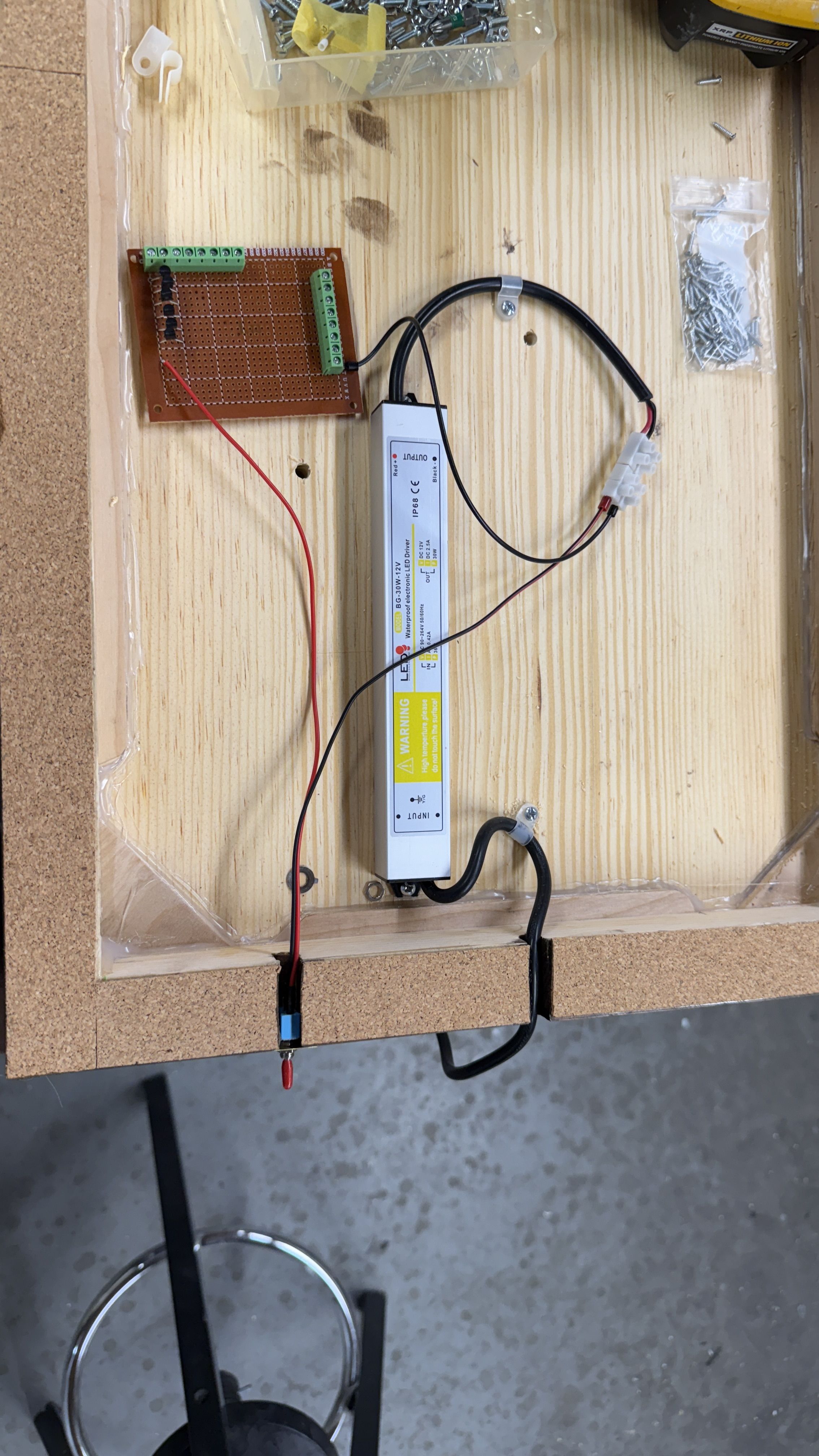
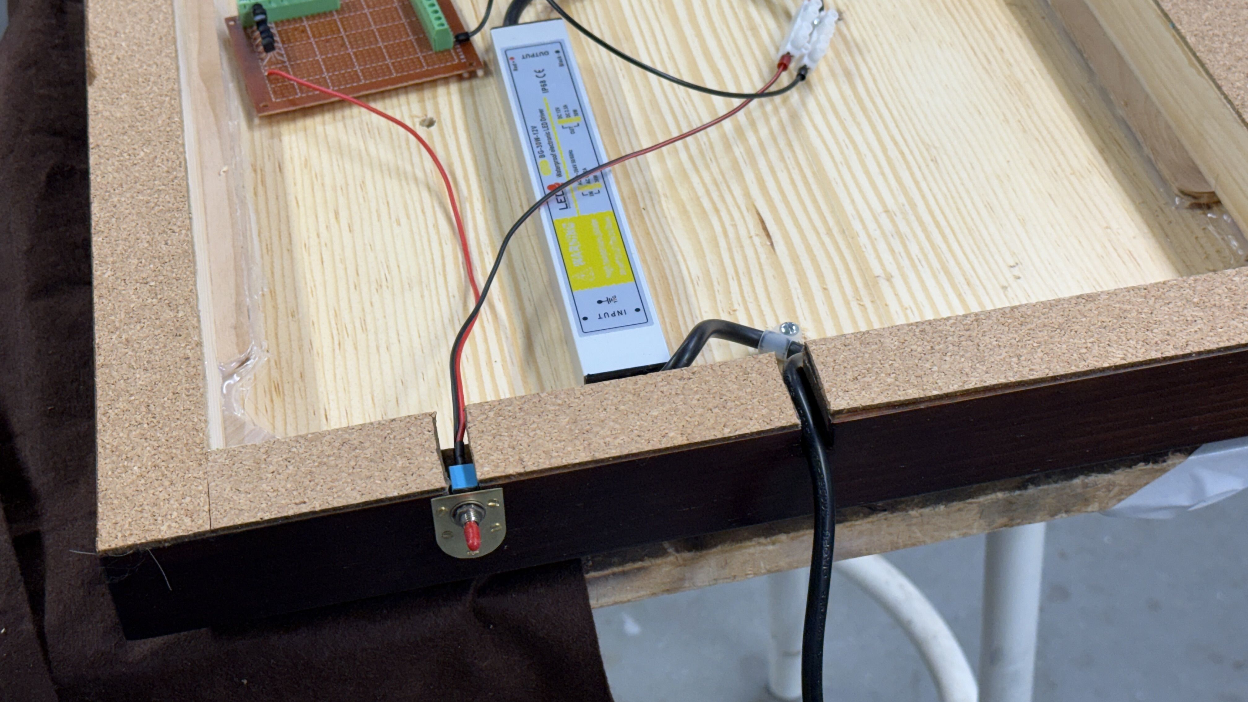
This post covers two days. Yesterday, I finalized attaching ALL the electrical components below the base. What’s left will be the very last task performed, after the case is built and mounted, when I turn it on its side and attach all the field LED leads to the circuit board. It’s AFTER the case is on to protect turning the model on its side.

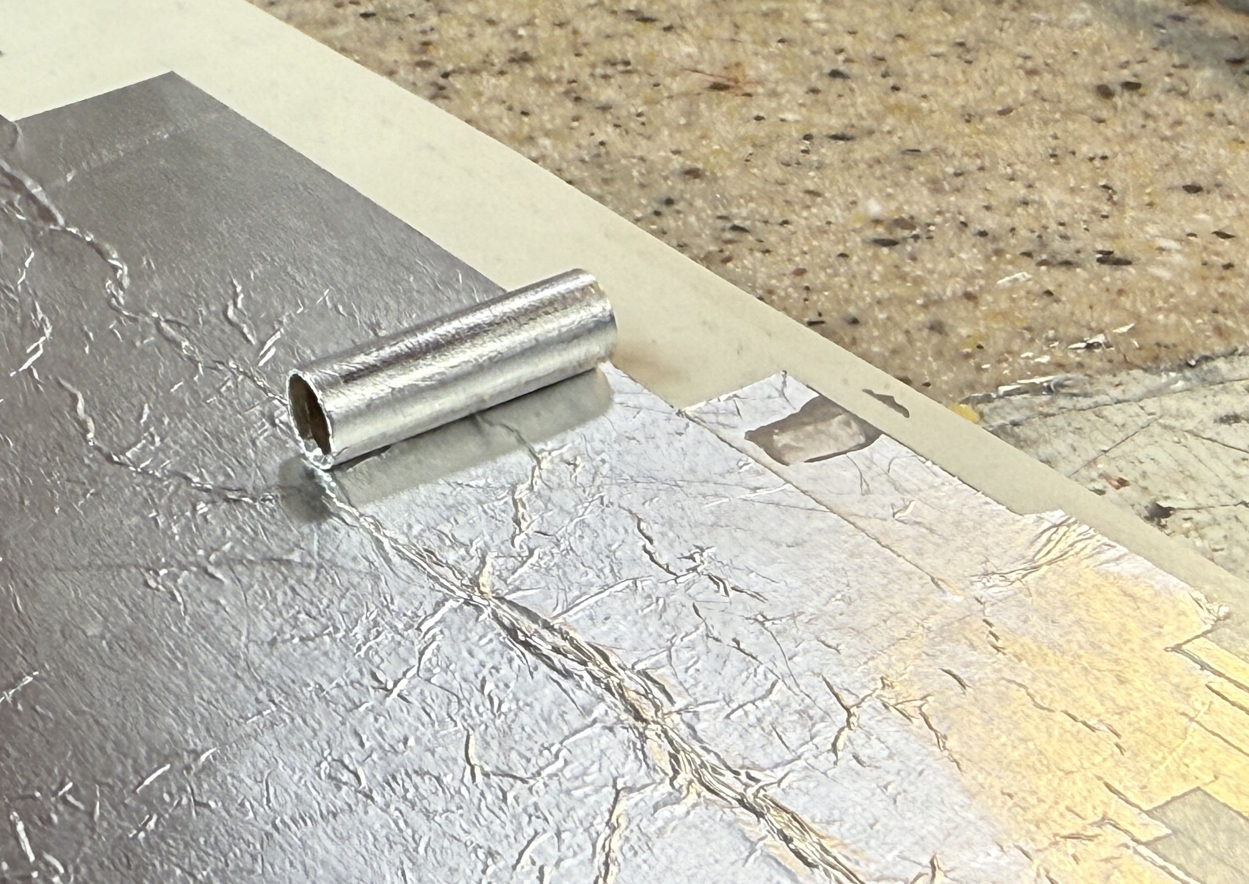
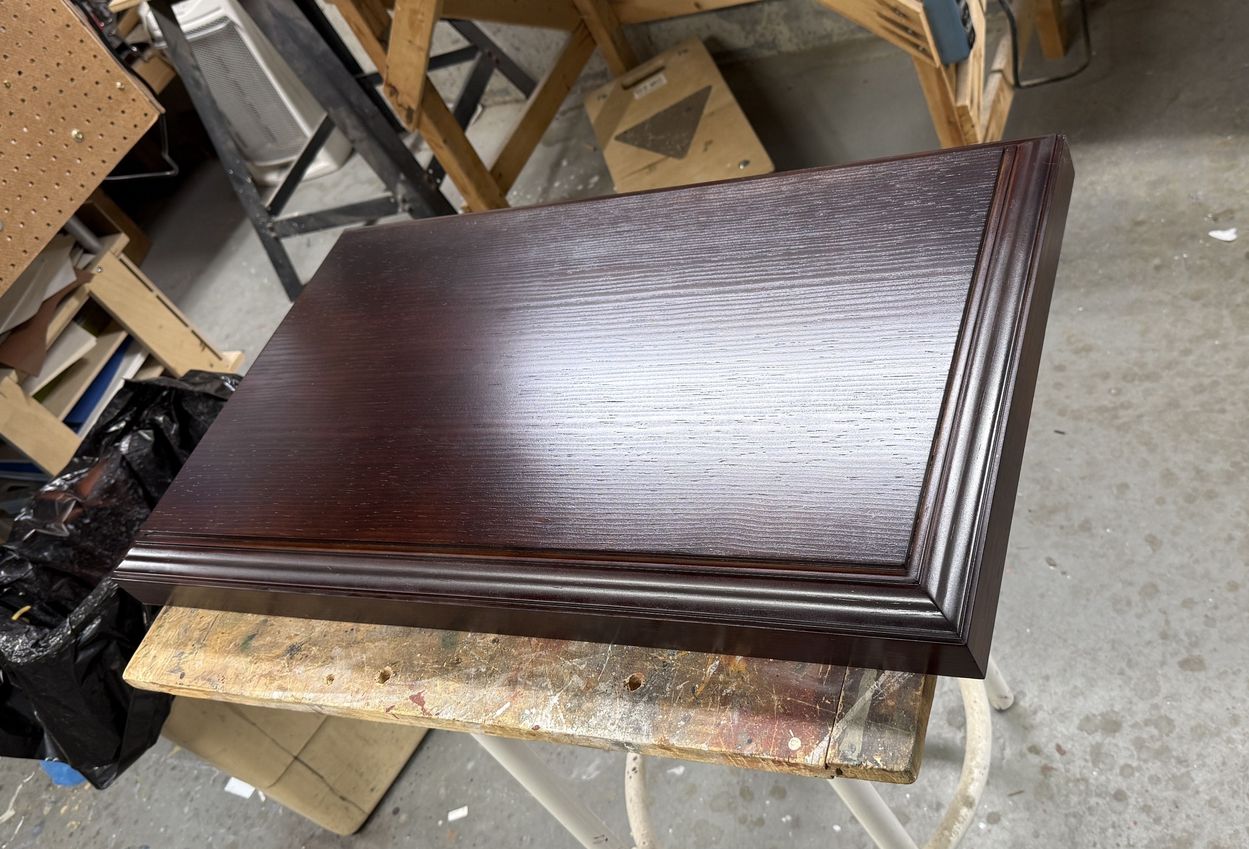
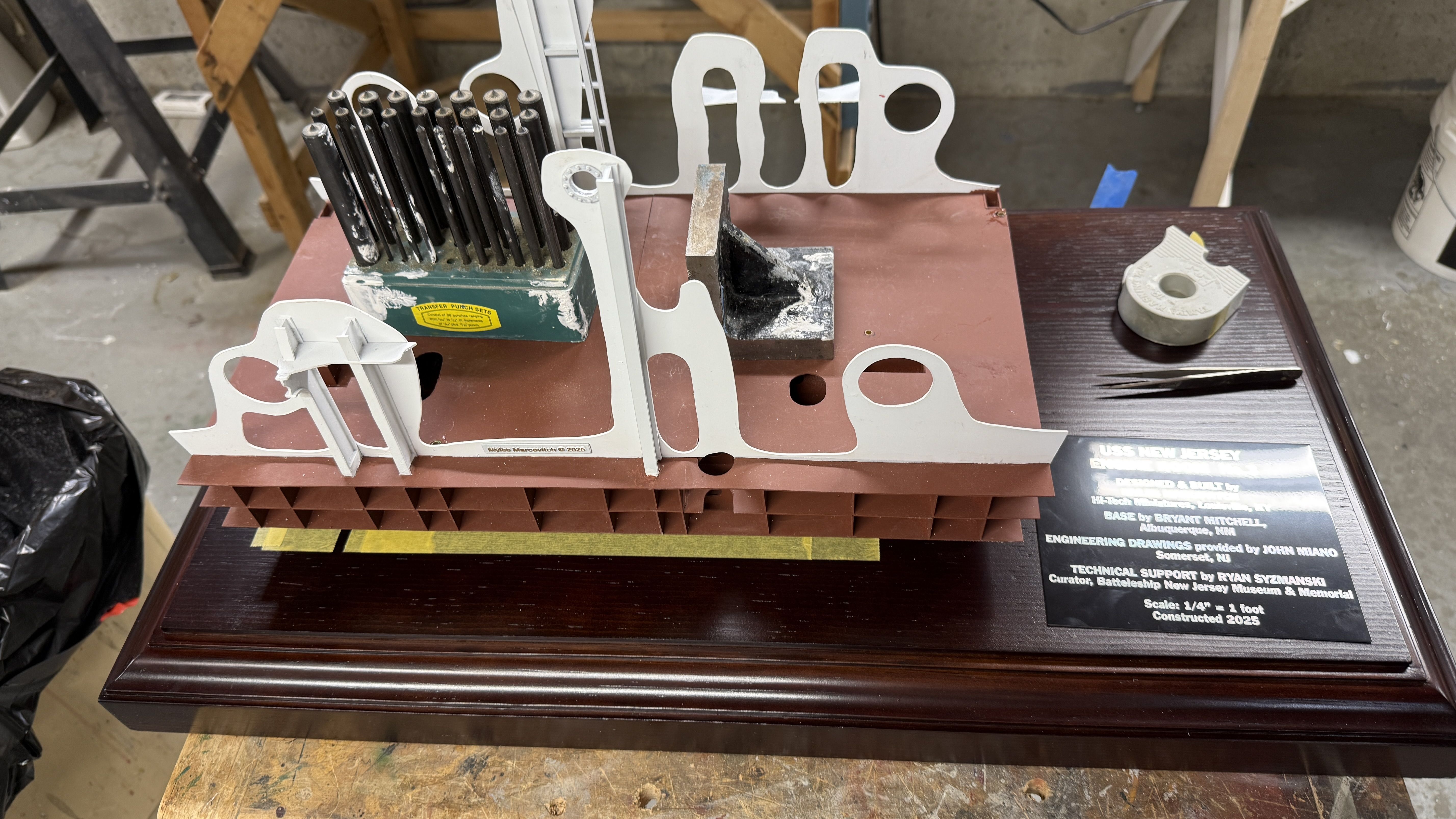
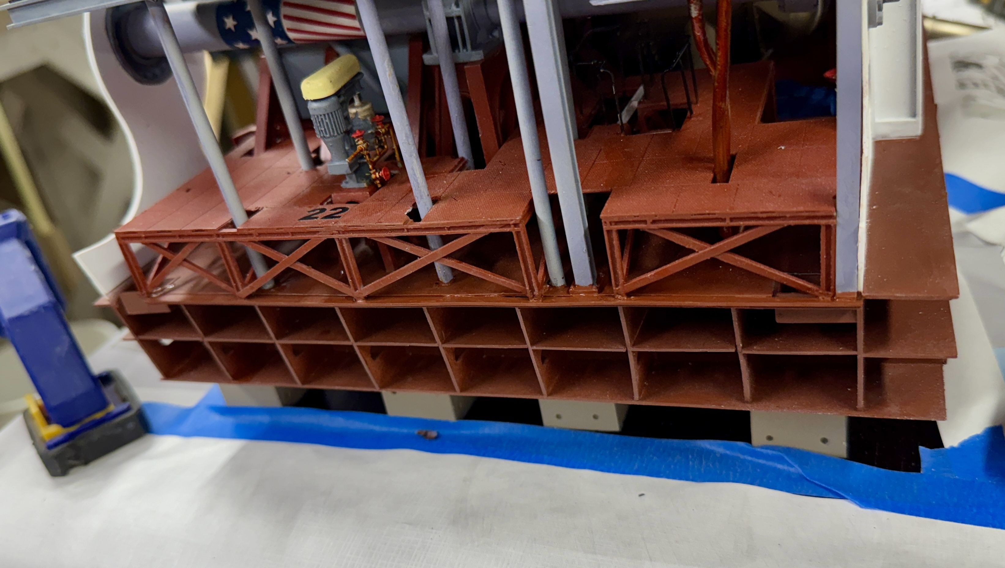
I flipped the base over and got ready to permanently affix the model to the base. Flipping the bare model on its side, I peeled the backing film off the double-sided, foam servo tape. This stuff holds like crazy and, unfortunately, holds its backing film with equal force. This image represents almost an hour’s effort. A couple of the faux dry dock blocks popped off due to all the manhandling and had to be reattached. Slowly, I started to get a bit better at getting the backing off without either pulling off the foam tape or breaking off the blocks.

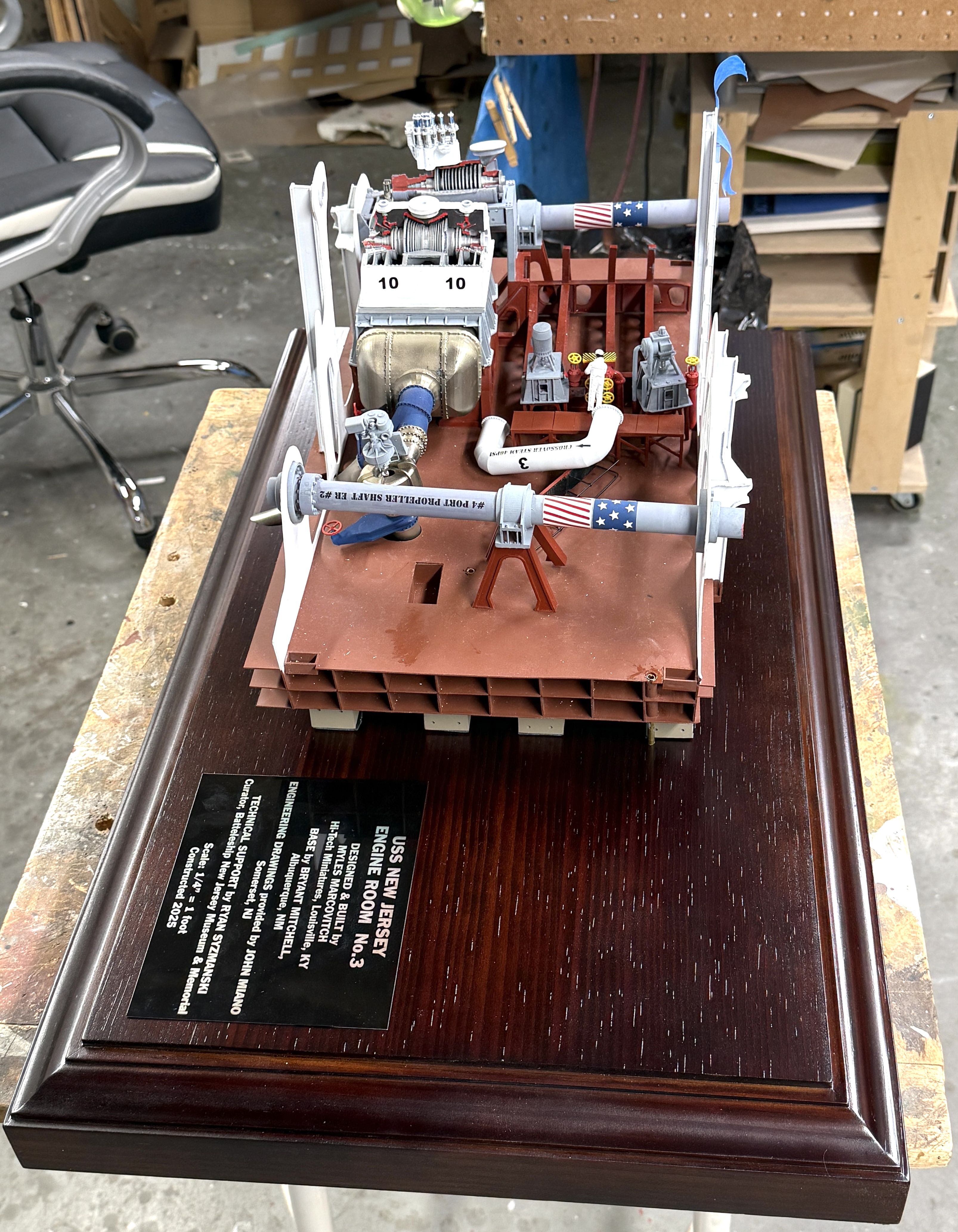
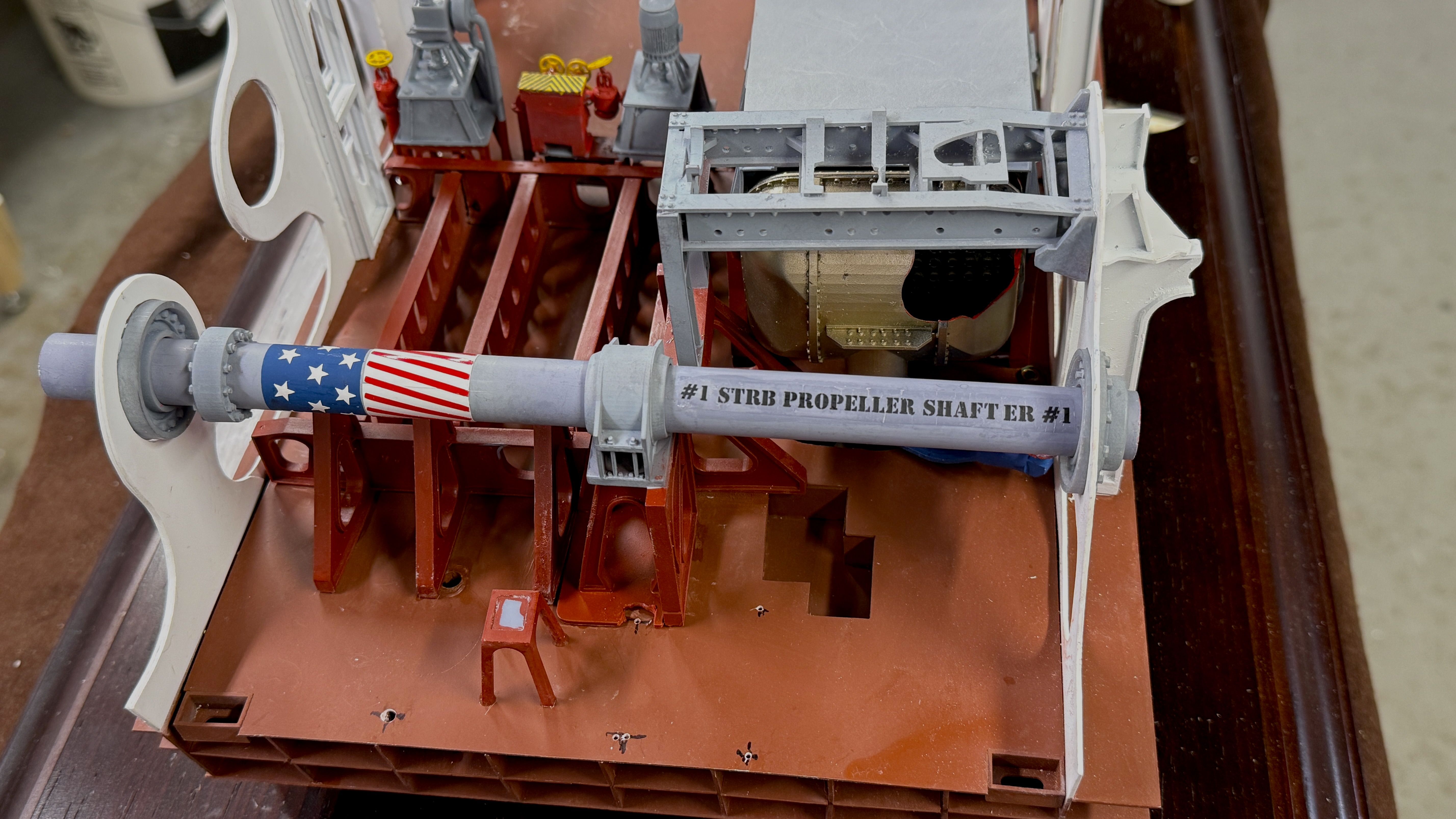
Once all were open, I carefully held the model against the masked lines and pressed the model onto the base. I was rewarded with an extremely firm adhesion. I could probably lift the entire base by pulling up the model, but resisted the temptation for fear of catastrophe if I was wrong. Each block may not be that strong, but 24 of them have a lot of collective power.

​I’m glad I chose to go with the dry dock blocks. It made it more understandable (to me) on how to fasten the model to the base.

Today I went to General Rubber & Plastics to pick up the cut Plexiglass. It was supposed to be cut next week, but they were early and I’m happy. Monday, my good model buddy, Chris Bowling, is coming over to lend a hand, and having a master builder like him around to help with the case glue up is great. All the pieces look like they fit pefectly. When you’re in a model contest where Chris has an entry, the best you can do is 2nd.

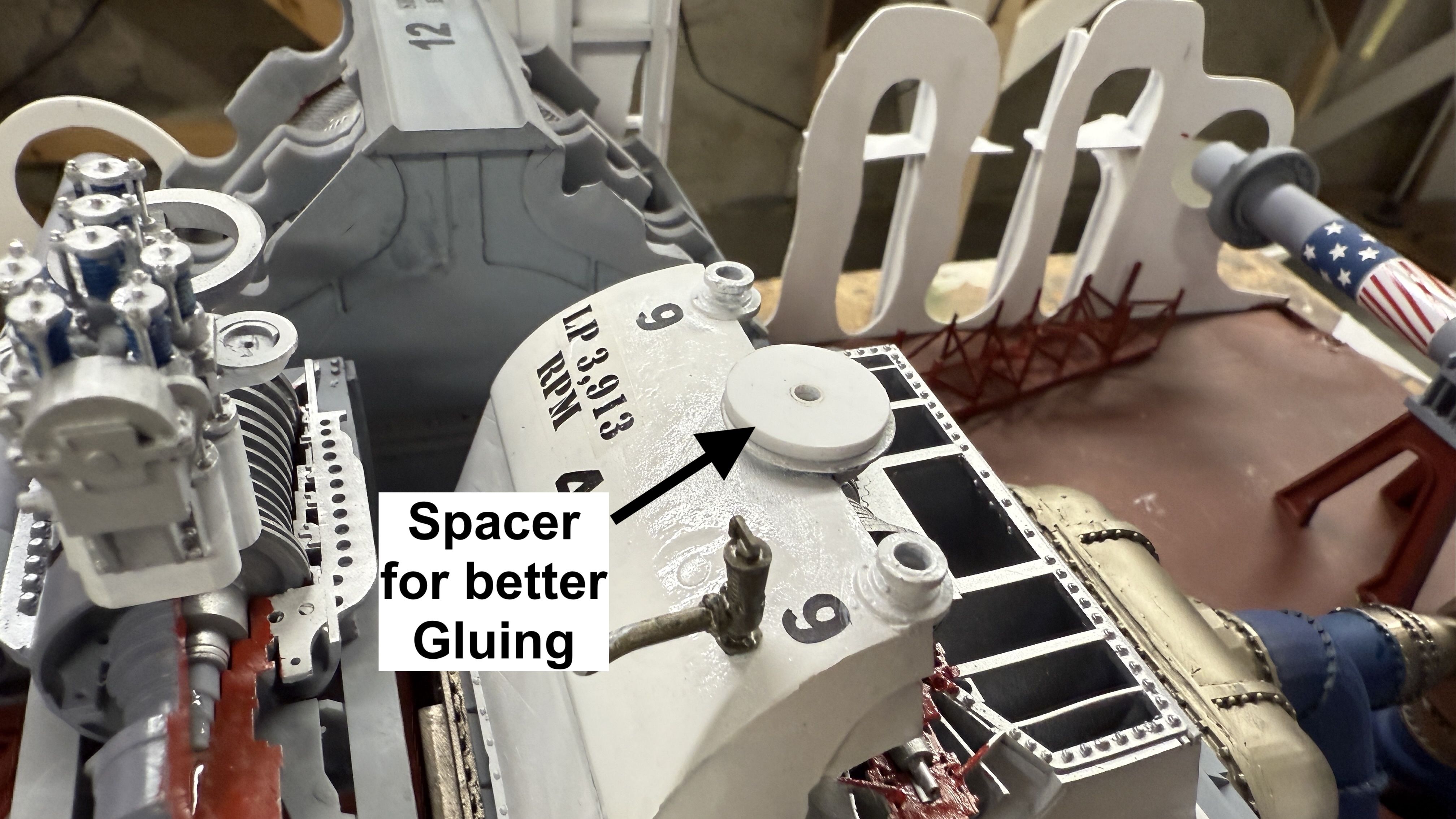
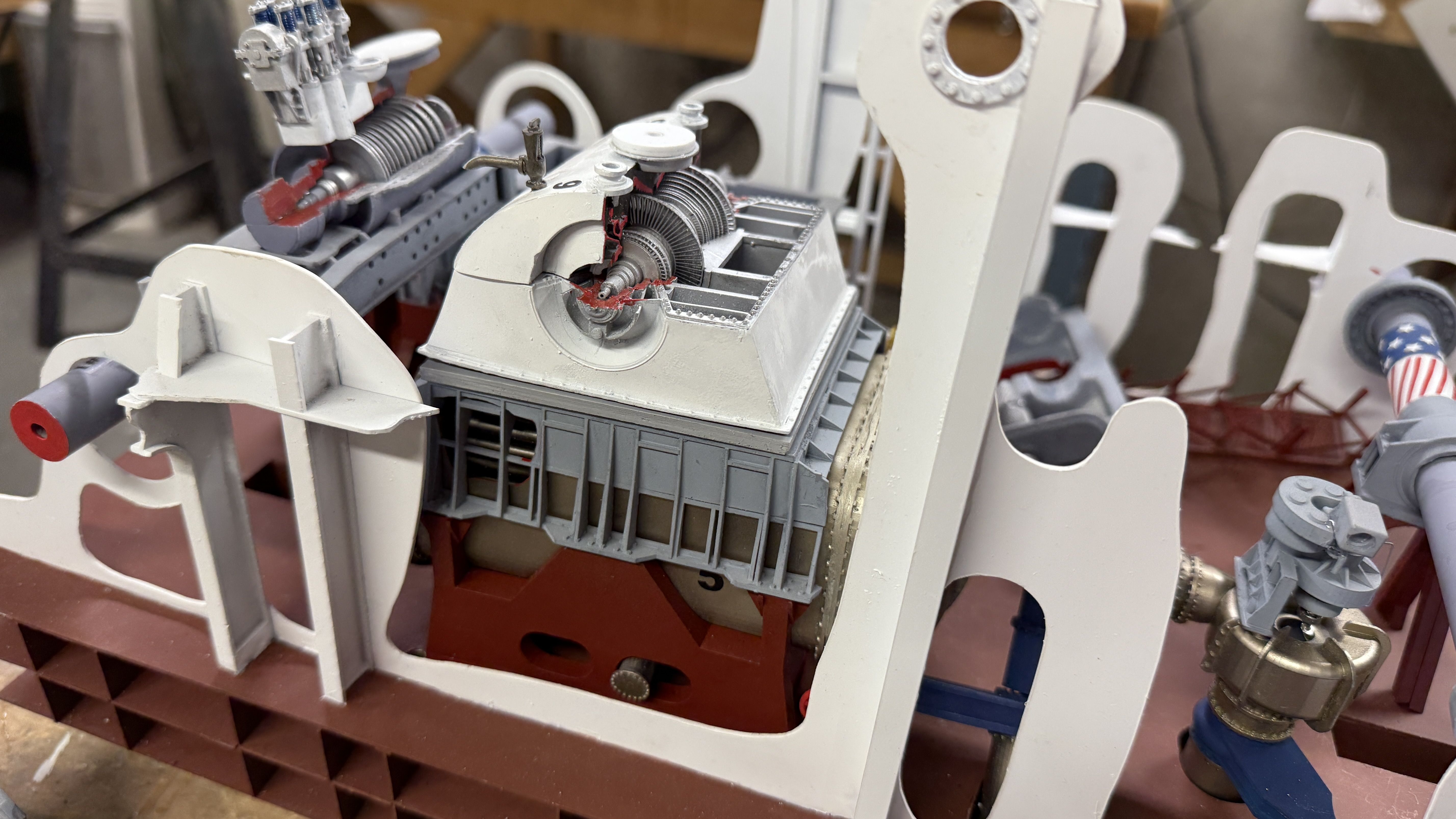
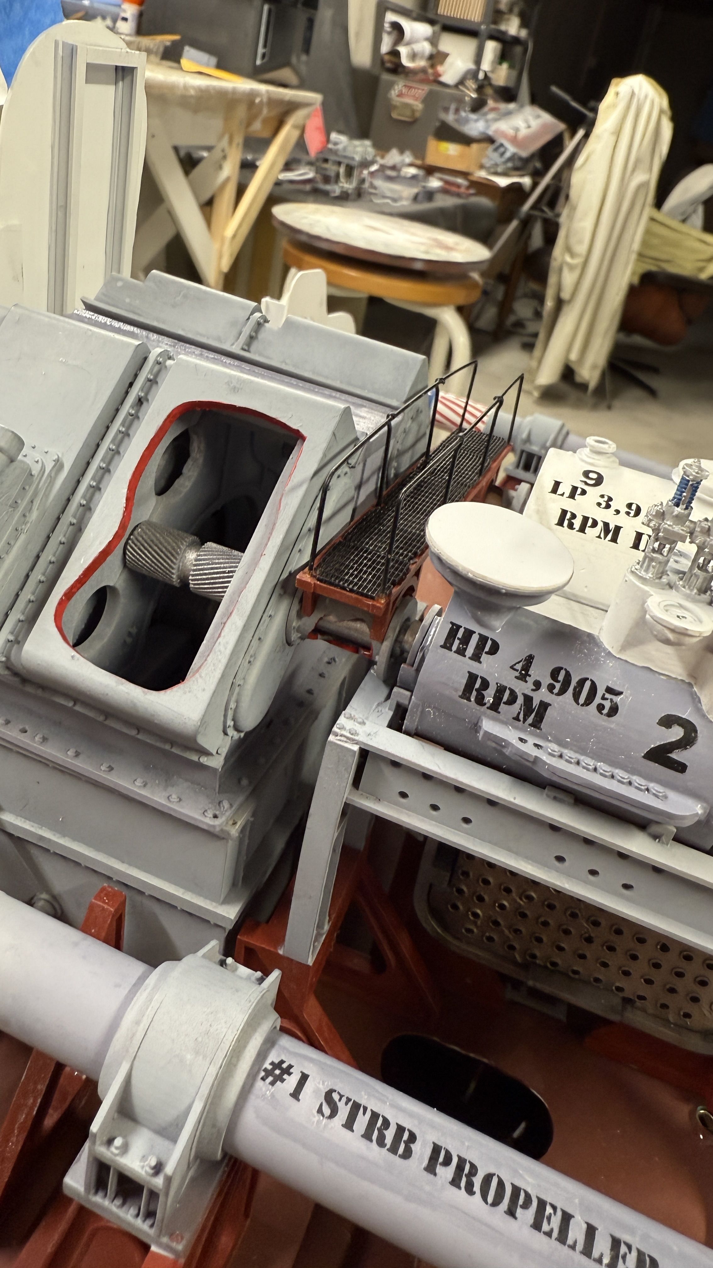
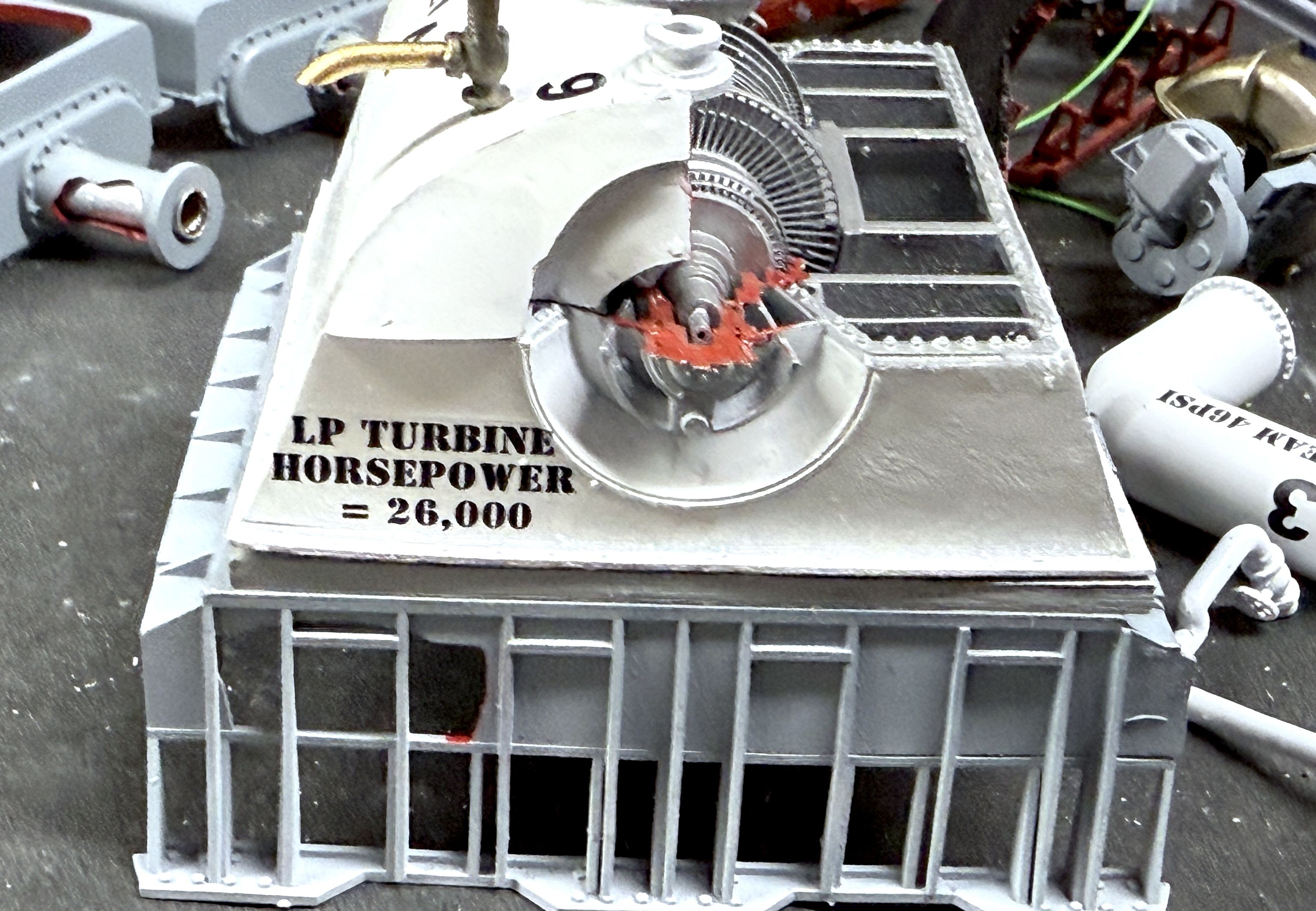
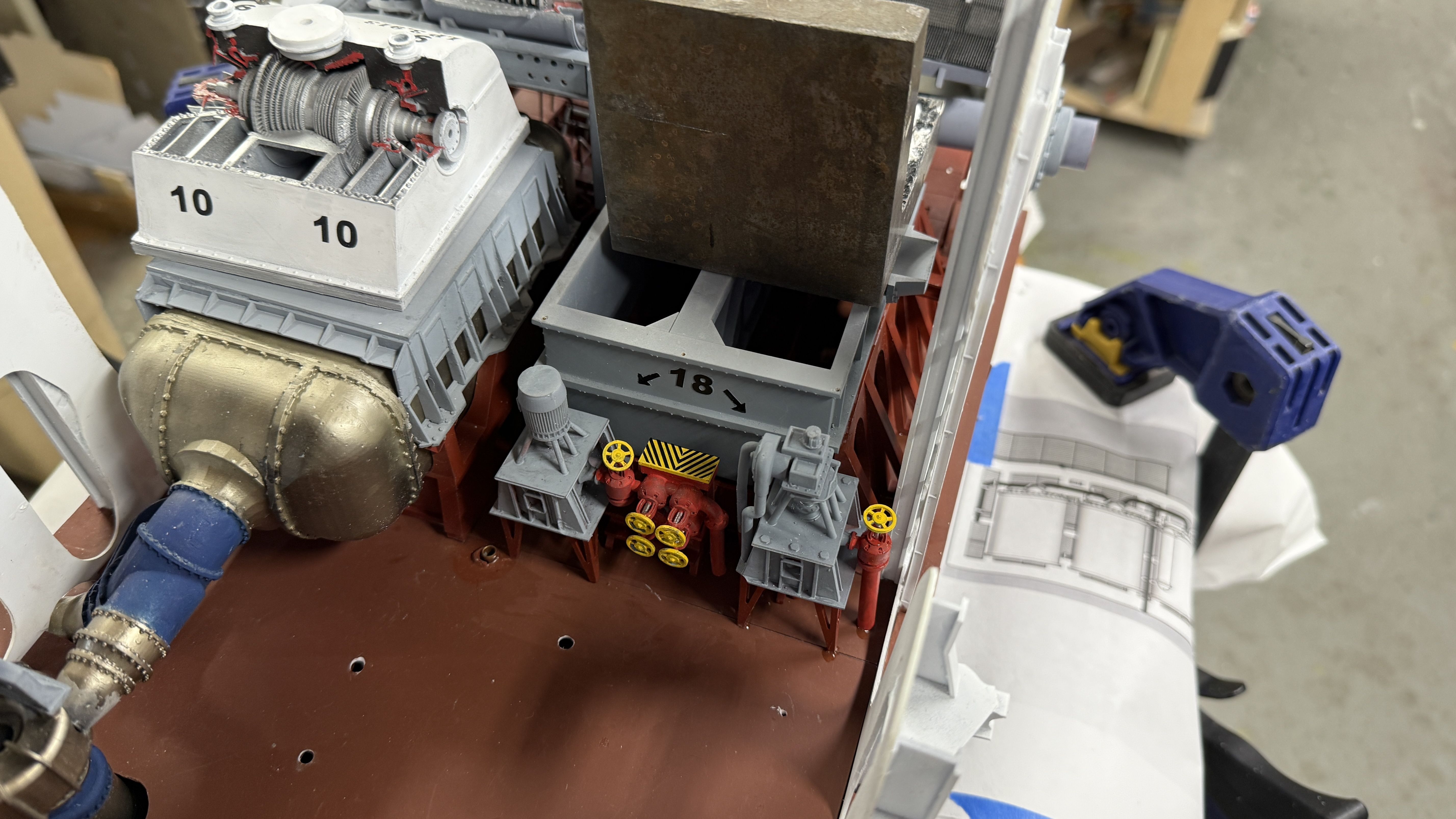
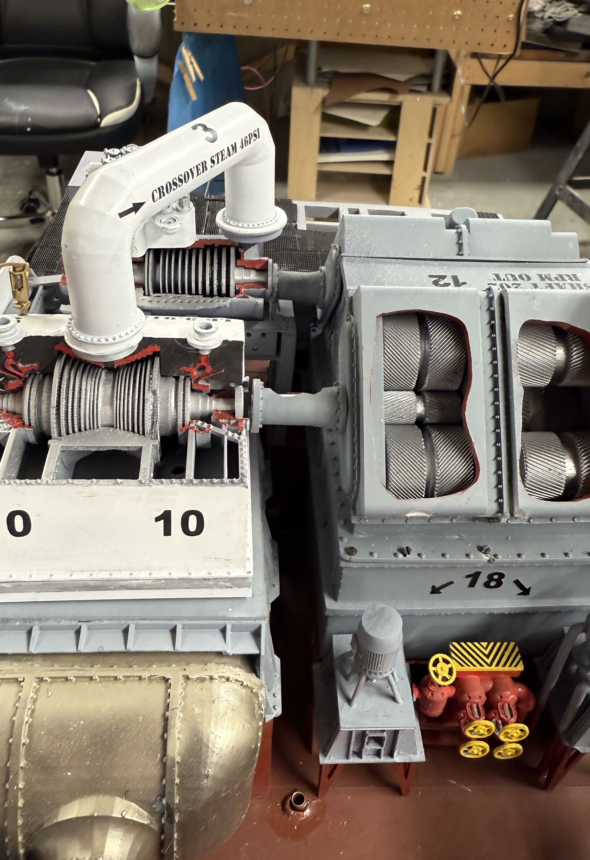
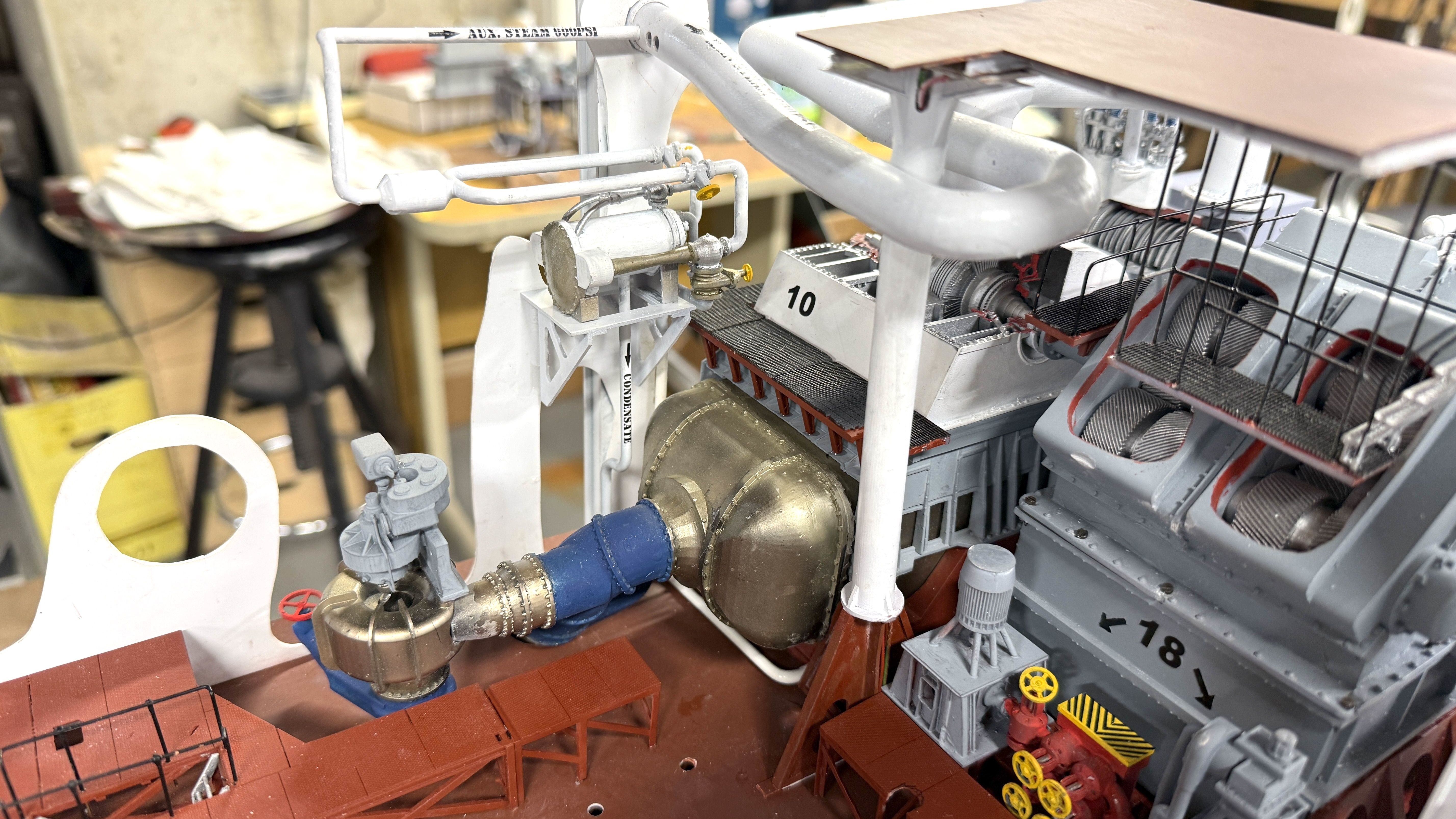
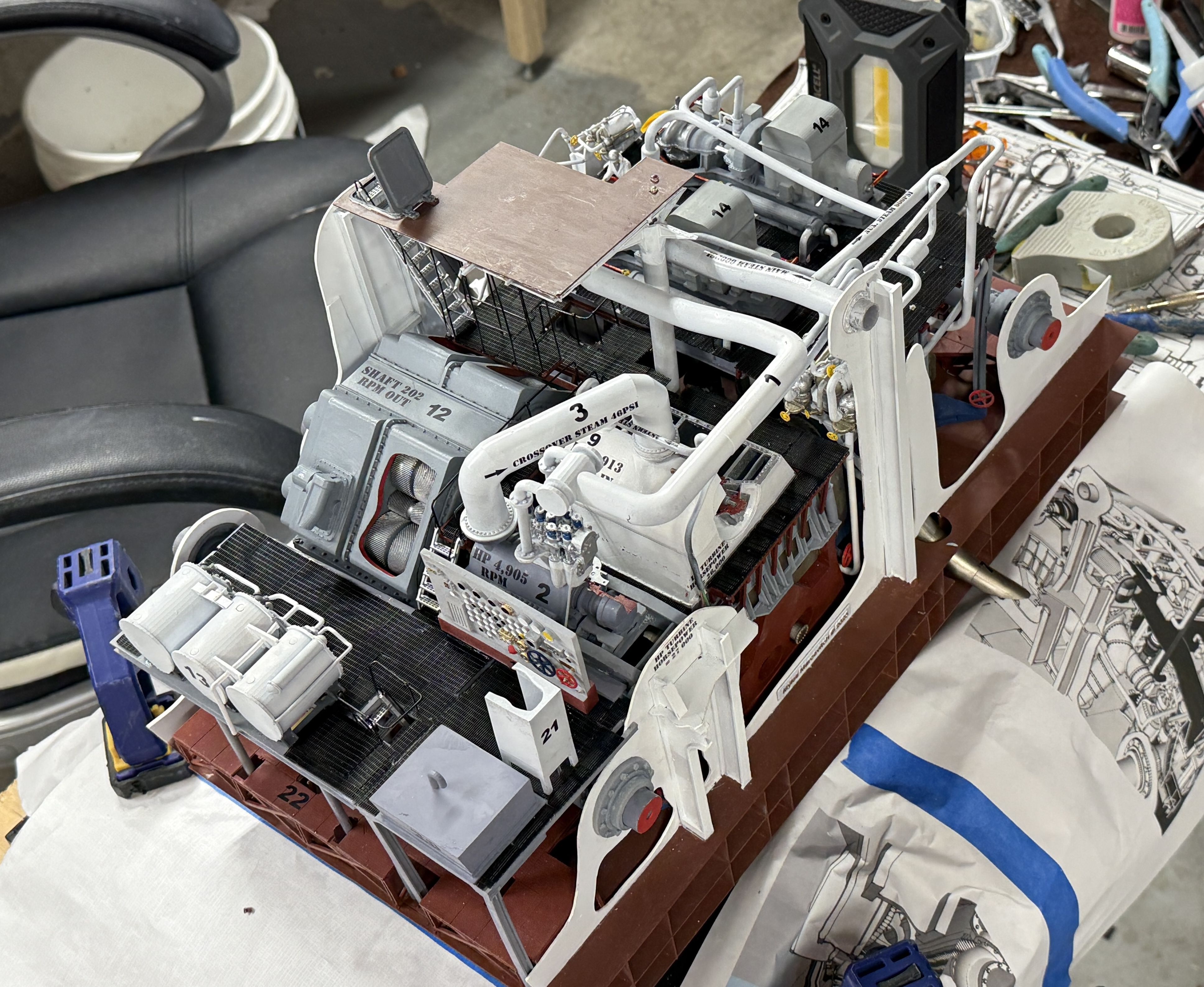
Back in the shop for a short session, I added some horsepower decals to the model. Having the RPM numbers without the horsepower numbers seemed incomplete. I also added the latest RPM decal to the repainted MRG top.

There’s not enough clear space on the HP turbine itself, so I put the decal adjacent to it.

i still have to add a new number “12”, which will happen on Monday after the decal is fully set.

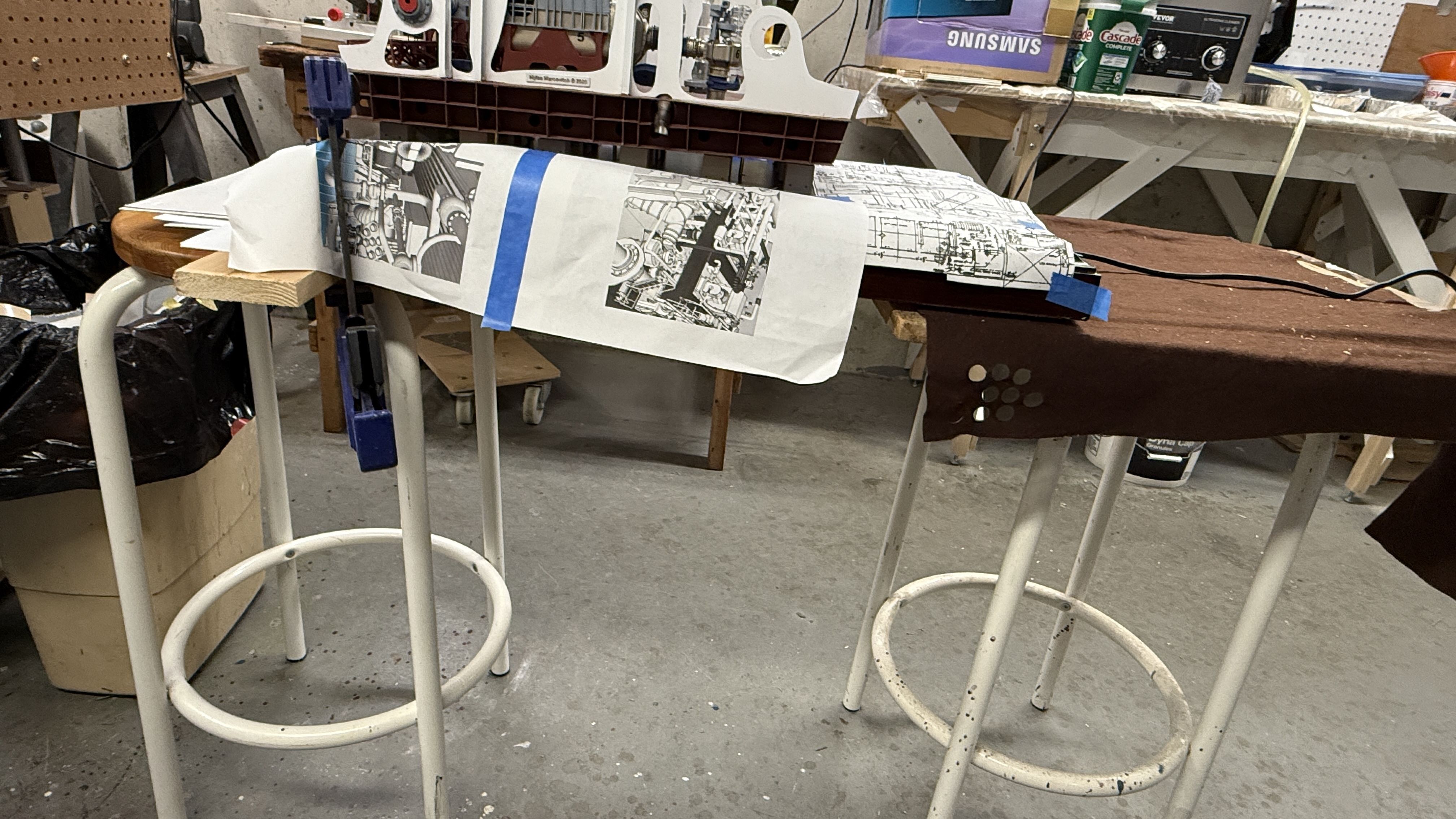
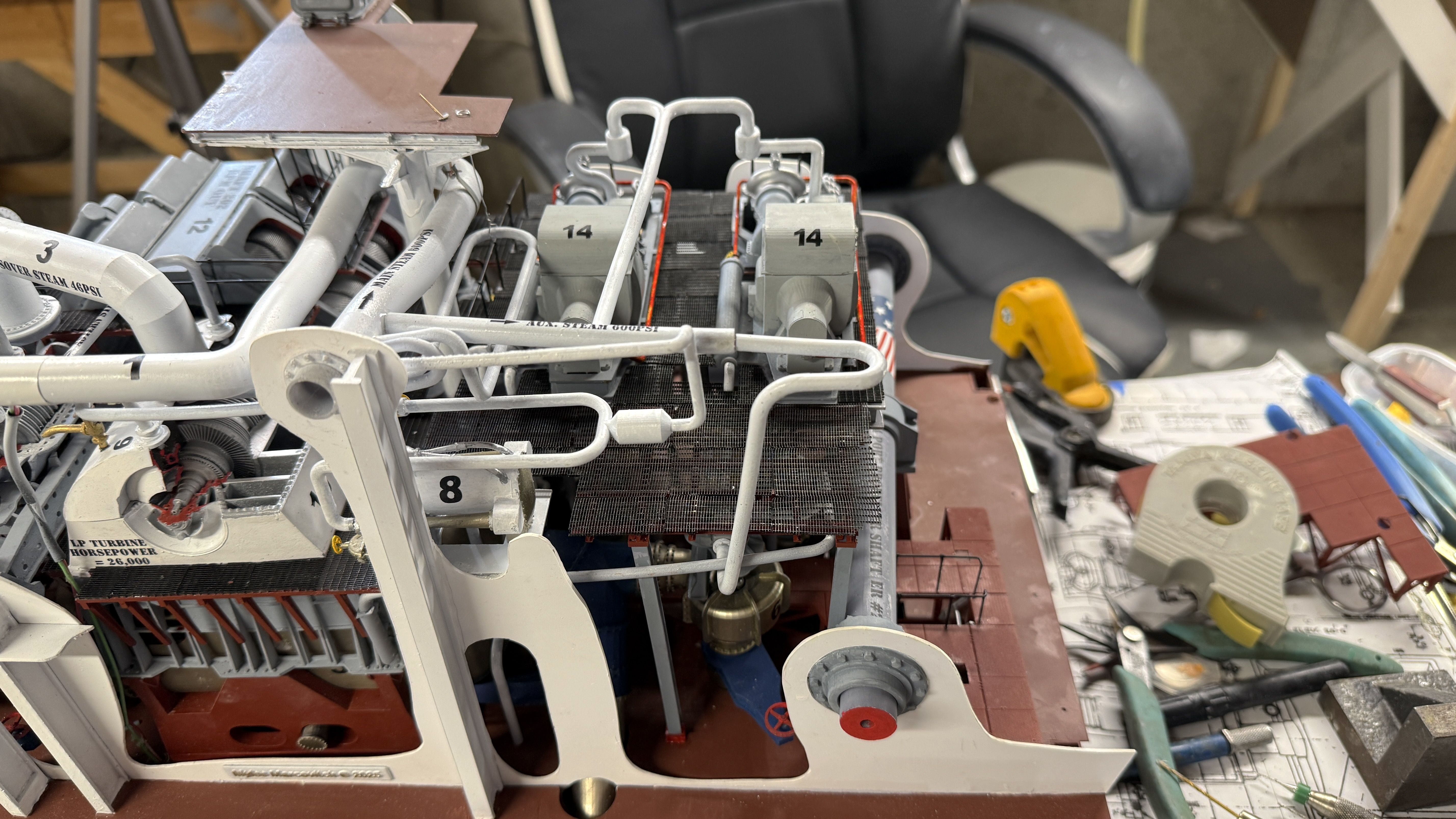
Now to the next very challenging task. Arranging and marking the location of all the units and their mounting pins. I’ve chosen to do this by re-using the floor template sheets. I added the holes for the main condenser piping and will situate all the units in their exact final locations. First thing was setting up some 3º guidelines to ensure that the MRG/HP and main condensers are all rotated on that bias. Then I laid on the TG unit AND the work platform that spans the gap between them. This platform (and others) are critical in spacing out many of the unit positions on the model. I got it in position where it looked right. I couldn’t nest it into the I-beam TG frame because the TG is proud of the surface by the height of the mounting pins. They will be sunk in holes when in final position. This entire exercise is to locate those pin holes.

I had to trim the lenght of the big lube oil filter’s piping since it was restricting my ability to move the TG unit fore and aft for final positioning. Their length was just an approximation anyway. I don’t really know where the pipes go on the ship. They’re under the floor plates.

So… the task is to locat these kind of things on the template, make holes in the template and then spot them on the actual floor. I chose to do it this to keep as much damage off the real floor as possible. To complicate things I’ve created two different kinds of mountings. Oh well.

Monday will be taken up with building the show case, and further work on equipment locationing.

Everyone have a nice weekend. Weather here in Louisville will be spectacular. Tomorrow is my model club’s annual judged exposition. Our club, the Military Modelers Club of Lousiville, is celebrating its 50th anniversay and the two founders are still members. One, Brian Bunger, is the propietor of one of the best hobby shops in the USA, Scale Reproductions, Inc. He’s an avid and masterful model builder himself and the shop reflects his love of the hobby. The club has many fabulous builders and I’m very proud to be in their company.

4 Likes

Today was a major milestone day! My friend and master-modeler, Chris Bowling, came over to lend a hand. And boy did I need it. It took too experience builders to pull it off. To give you a taste of what Chris can do, this was his entry in out model club’s annual exposition this past Saturday. It started as a paper model kit of the launch platform and crawler, and then after about 4 months of intense efforts. The shuttle Atlantis is a Revell kit that is greatly enhanced. Scale is 1:72.

We located all the untis with columns and drilled all their mounting holes. We intalled, permanently, the main condenser and main reduction gear foundation. And then started installing more things that go around it. Everything was installed with 5-minute epoxy and they are very secure. We probably spent an hour getting the turbogenerator unit positioned and settled down to the correct depth once all the pin holes were cleared of any interference from the plastic lattice that laid below.

Intially, we used the paper template to mark hole locations, but found that the paper was fouling the pin holes making it hard to settle down to full depth. When all of the columned platforms had their mounting holes confirmed, I permanently installed the main condenser. This was a 3-step process. First, the condener pump was CA’d on the tapered pipe end, and then the main body was epoxied to the hold floor. Before gluing, Chris sanded the oxide red to provide a good gluing surface. Epoxy set in 5 minutes and then I glued on the startboard end. The handwheel on the big gate valve just bumped the bulkhead, but we could still get the condenser correctly located. The LP turbine foundation was CA’d to the supports flanking the condenser.

When cured, we located and marked the positioning for the MRG foundation and did the same sanding job. The foundation was spoxied and held in place with gravity clamps. The HP foundation was help lavel and clamped to the bulkhead while curing.

At this point Chris had to leave and I continued adding the starboard #1 prop shaft bearing and the lube purifier foundaion with epoxy. The seal bearings are not glued in yet.

I also glued in the separate steam powered lube pump which has been floating around on the parts table for a long time.

I had to relieve some of the bearing bores in the MRG to get the gear coveres to lie flat. I then epoxied the gear covers with the reduction set installed and clamped with lots of clamps. Gear box will be installed next.

Chris helped me and finished sanded all the glue edges on the plexiglass in preparation for glue up tomorrow. I can do that without help. Chris is returning next monday to help some more.

It’s really exciting that this is actually reaching this point. It’s going rather fast.

7 Likes

Dug into building the enclosure today. I thought I was doing everything right this time. It is my 5th clear case build, so I should be getting better at it. I’m almost there…

The plexiglass is sitting on a wet towel and I wiped down all the surfaces after peeling off the protective film. This is supposed to kill any static charge. It generally worked. I was very diligent in applying the masking tape to hold it all together. The cutting measures that we determined were perfect. I started with Tamiya tape, but it didn’t exert enough pull holding the parts in alignment. I substituted 3m Blue Tape and it worked better. What didn’t work so well was when I filling a pipette to transfer liquid solvent to the needle tipped bottle. I had my reservoir at the back of the table and after I filled the pipette and attempted to bring to the bottle it unloaded a splash onto the interior plexiglass. It happened again I had a spurt come from the needle applicator. I didn’t touck the solvent and let it evaporate. It didn’t mar it too badly. Luckily, one area is where the key is going and won’t be visible. The other areas of trouble was a little bit of seepage under the tape. I’m not sure what to do about that. I will let it cure totally over night and see what I can do tomorrow. I have plastic polishing materials. The case fit nicely. And I did mount the key with 3M Transfer Tape. The key is double sided and it can read from both sides of the case.

The glue up of the upper main reduction gear case when very well. Today I glued up some more for the lower part of the asembly and will put the unit into the model next session.

The rest of the session was spent wrestlng the startboard floor and the evaporator/main gauge panel decking to play well together. They weren’t! Chris and I spent a lot of time yesterday trying to align the flooring with the columns and locate the pin holes. Today, nothing fit and I had to do more surgery cutting away portions of the flooring so the columns could find their respective holes. I think I got it figured out at the end of the session and will get it all buttoned down next session.

I’m thinking about model #4 and could most likely do the steering gear. I did a quick drawing and scaling of the rudder and, yest, it can be printed on my printer as a single part. That helps a bit. As with the engine room, the project will hinge on getting good drawings from John Miano. John owns many microfilm reels of all the New Jersey’s engineering.

4 Likes

Since many of you have been following my pursuits in model making, you also know that I often have to deal with calamities. Yesterday was no exception. That said, progress was made. First the progress. I got the starboard floor in and the evaporator decking that sits over it. I installed the lube oil purifier and the lube oil settling tank. And most importantly, I got the main reduction gear installed. I also spent a lot of time finally getting the turbines and MRG shafts to align properly.

Before I got started, I needed to adapt how I was supporting the model to have access to the bottom. In addition to getting all this stuff positioned and glued propperly, I have to feed all the LED leads down through the base. I took another stool of the same size, screwed a board across it to match the height of the other, and clamped the model across the two leaving a gap wide enough to expose the entire underside of the base. Notice the protective paper I was thoughtful enough to put over the delicate woodwork. What you can’t see is the one end (left end) that I didn’t do this, based on the erroneous assumption that it was such narrow area, what could possible damage. Hmmm….you can see where I’m headed here.

Gravity clamps ATTEMPTED to hold the floor in place while epoxy was curing. See that exposed wood…

To hold the upper level in place I also used gravity clamps (not shown). Then two things happened. One of the angle blocks fell off and dinged the wood base. And then the extension nozzle on the CA bottle blew off and a huge glob a medium viscosity CA landed directly on the wood. I wiped it, but it did damage the finish requiring work to restore. And to make matters worse, a thread of epoxy ended up on the base as well. All this because I was stupid enough to leave one area exposed. I can fix all of this damage, but I didn’t need the extra work.

​Notice that the floor legs ended up off the hold floor. Nothing I could do could get them in proper position. The floor was bumping into some part of the MRG structure. What madeit so frustrating was the time Chris and I spent aligning everything before gluing down the MRG foundation. And yet something had to have move about 1/8 to 3/16" to narrow the flooring space. I have two choices. Leave it as it and just hope people don’t fixate on it—like I am, or rip out the floor and redesign it so it can be inserted in sections and fit around the columns, which aren’t going anywhere. I’m going to do the redesign and see if it makes sense to do.

Gluing down the MRG started by gluing in the lower portion. Again, gravity clamps help it in place until epoxy set.

When set, I added the bull gear and then screwed (not glued) the upper works in place. One corner was sitting high and the tiny screw was stripping the resin threads so I added some more and it’s holding. It was much easier screwing this together than epoxying. I thought of doing both, but the screws seemed to be holding well. The turbines and crossover pipe and not permanently installed yet.

To get the LP turbine to align I had to add another 1/8" shim on the bottom. Again, I don’t know why this shift happened. Previous fitting sessions had it aligning without this shim. A similar issue occured with the HP turibine, It was interfering with the torque tube and I had to grind off part of the HP Shaft and surrounding shell. I also had to slightly modify the HP frame, but as you can see by the above, they are aligned really well.

I permanently installed the strbd prop shaft including its bulkhead seals. And did the same for the MRG prop shaft seal. That’s all done!

Here’s a view across the back of the MRG and a comparable view of the real thing. The resemblance is deliberate and gratifying.

I just noticed that the lower foundation is gray not red. In my engine room it’s now RED!

​The lube oil settling tank is in and the pipes lead down below… somewhere.

And lastly, here’s an overview shot of the assembly so far.

There’s some more touchup painting on that extra shim under the LP turbine and then I’m gluing down both turbines and the crossover. BTW: that crossover fit was one of the key parameters that I had to hit. Another thing that did not go wrong.

No work today. It’s Yom Kippur. Work will begin tomorrow.

5 Likes

After spending about an hour attempting to design a new floor system that coule be inserted from the edge, I realized that, while I could get the left-most part to do that, the rest, especially the right-most portion would not and I scraped the idea turning to plan C. Plan C, suggested by Chris, is to make a small extension to the floor and fasten the overhanging legs there. This actually worked okay. It’s not real pretty, but the legs hanging over were just plain ugly, so it’s a definited improvement.

In order to give it strength I made the bottom piece 3/4" wide and notched it to clear the longitudinal frame members. I initially used Testor’s styrene tube cement, but had to add Tamiya liquid cement and then rubber-infused CA to deal with stubborn areas. There was a glitch that was causing the trouble; the pins from the columns, although I clipped them shorter, the were still protruding a bit and were keeping the styrene from adhering to the styrene decking.

The finished job could be better, but it solved a problem and the outer floor supports are now grounded on something solid and not just hanging out in thin air.

I’m detecting a patten… Somehow, the MRG foundation and/or the main condenser about 1/8" off of the ideal position. That 1/8" has been repeating itself everywhere and causing all sorts of things like the fit of the flooring, fits of the turbines, and fits of the catwalks that surround them. I can’t fix it, so I have to adapt to it. The units are very well epoxied in place—as they should be—and can/will not be removed.

On one of my other forums to which I post this thread, one of followers was an electrician in… guess what… the Battleship New Jersey Engine Room #3 from 1967 to 1969 when it was activated for Viet Nam. He was guided to the thread by a friend and offered some comments and congratulatory statements. While he found a couple of inaccuracies, he thought the overall venture was wonderful. He’s going to be at the ship for the 250th anniversary of the US Marines and it may coincide with my trip to deliver the model. I would like to meet him.

I painted the LP turbine shim and fixed the broken relief valve. I broke off one and had spares. It’s ready for installation. Before doing that I started fitting the various catwalks and found that 1/8" error causing some weird fits. Nothing too critical! In this image, the forward platform in front of the LP turbine is protruding past the bulkhead by 1/8" or so. It’s supposed to lie just behind it.

But, before going further with the propulsion plant, I installed the central column. The 1/8" again showed with the upper part of the entry hatch floor 1/8" offset to the port side. I could still epoxy it in place, but it’s not exactly placed as per the plan. I needed a little shim under one angle support under the column, but will be invisible after painting and all the rest of the starboard side equipment goes in.

We leave on vacation next Friday, but I should get plenty done from Monday thru Wednesday. I think all the goodies will be in place in a couple more work sessions. That’s assuming nothing breaks or I have to redo something to get a better fit.

Have a nice weekend.

3 Likes

I’m wondering if, among the museum visitors that see this (and your two previous models), there will be at least a few avid modelers - I’d have to guess there will be.

Perhaps consider adding a label to the display - not necessarily prominent - with text “Click to view details on making this model” - with a QR code to point to the correct thread on this forum!

1 Like

I did that for the 16" gun and will do it with this one also. For the 5" gun, I prepared a narrated slide presentation about the system and model. I tried narrating it myself, but didn’t like it and asked Ryan if his communications manager could narrate it. He agreed, but it’s not happening. For this model besides the QR label I was hoping to make an animated walk-through of the model, which as we know, can be done using SketchUp and V-Ray. However, my MacBook Pro 2019 is not up to it. It’s having great difficulty handling the size of the full model. I see the beach ball going around and around for what seems like many minutes.

I will add the QR label for this model and bring one for the 5" project since the slide show doesn’t seem to be coming.

1 Like

I satisfied a couple of critics today. I was able to reposition the electrical control console with minimal damage. The reader who worked in ER 3 said there had to be a man-sized gap between the console and the electrical cabinets. I knew that my spacing was off, but was reluctant to atttempt to move it for fear of wrecking the paint and not having enough slack in the wiring. It the wires were too tight, I would have to de-solder a joint that’s already had that done before, and splice more length. As it worked out, there was extra wire nestled under the console. I had adhered this unit with the 3M Transfer tape and it can be pulled apart. It left some adhesive debris on the paint and I was able to get that reasonably fixed. I added some rubber infused CA to further adhere the unit since the transfer tape was no longer pristine. Touchup paint finished the repair. Not perfect, but funcitiionally correct.

I didn’t like how the elongated torque tube was pushing the LP turbine forward. It made the front catwalk stick out past the bulkhead. i took an 1/8" off of the design and reprinted it today. While the print was perfect, the catwalk was still just a bit proud of the wall. I went back to the origianl length part (didn’t discard them), and the catwalk fits as it should. The crossover pipe is just a little iffy and I’ll have to find the sweet spot to get it center on both turbines.

I spent over a half hour replacing the barrier film on the 3D printer. It was at its 60,000 layer limit and replacing it is essential for continued success. I spent the rest of the session practicing how to install the main air ejector (MAE) its associated piping and the exhaust steam pipe from the main condensate pump. The pump’s pipe has to feed through the MAE’s support frame. It’s a bit of a ballet. It’s not a good time to figure this stuff out when there’s epoxy dripping from everything. I had to fab one more pipe for the MAE, the condensate line back to the main condenser. I used a piece of Plastruct butyrate pipe left over from a long-completed model railroad project and bent it using a hot air gun.

More work will continue tomorrow.

3 Likes

As predicted, assembly work is moving fast. The units are big, but go in as single pieces. Today, the main propulsion system is in and piped including the astern steam lines. I got the main air ejector in place and fully piped. Main steam’s wiring is led down below. I got the catwalks fitted and cemented around the low pressure turbine. And I got the first flooring units on the port side installed. Again, I have to keep in top of mind what goes in before what or I get jammed up pretty quickly.

I found the sweet spot in positioning the hp and LP turbines so the cross over pipe was more or less centered on its flanges. This was glued with epoxy. Main steam was installed and it’s split feed glued into the input flanges on the HP throttle valve body. There is a lead wire coming down from this pipe for the LEDs that lie on its bottom.

Here’s the wiring disappearing beneath the floor.

It was time to get the fore catwalks in that surround the LP turbine. There’s a very narrow walk that lies between the two turbines and I was pleased that after fussing with the location of the LP turbine, the walk fit nicely. The larger catwalk that wraps around the turbine also was touch and go. The angular vertical braces in the front are not actually touching the LP support frame. I may be able to fix that so it looks a little better.

Next up was the main air ejector which glues to the front bulkhead. The vacuum pipe was a two-piece affair that had to locate somewhere under the main condenser. Took some fancy maneuvering to get all that cooperating. The steam inlet line ties in above to the main steam. This was adhered with epoxy and some med CA.

With the MAE in I added two more pipes that feed off of main steam, the astern steam lines. In the 1:1 model, they follow a curvy route, most likely for expansion with the 800 degree steam within. I attempted to duplicate this path.

The port flooring began with the front part. I had to stop there becase I need to install the turbogenerator unit and the port #4 prop shaft. Then the remaing floor goes in. I had to make some relief cuts on the walk in front of the lube pumps to clear the TG columns.

So here’s a shot showing progress to date. Notice how the pipes are sagging. These are supported by the ceiling hangers. I’m going fab some hangers out of brass that will hang from that little bit of ceiling from the stair entry.

And look at the dent I’m making in that massive parts pile. This is all that’s left. Could be done in two work sessions, but probably a bit longer for touch up work.

Stay tuned!

6 Likes

Nice to see how it is all coming together Myles!!

It sure is. I’m amazed that it’s gotten this far!

It’s gotten very difficult to see into the dark spaces to glue some things in. For example: after spending 1/2 hour to finally get all the pins on all the legs into their respective holes, I couldn’t reach in to add CA to the legs closest to the MRG. No matter how I attempted it, I a) I couldn’t see them, and b) even if I could, I had no way to get a glue applicator into the right spot. So those legs are not glued, but enough of them are to secure the unit… I hope. The other challenge was the clearances are so tight that things like pipe runs are bending around obstacles that, on the drawings, had clearance. The #4 prop shaft was very tight with the TG columns and the added leg to the forwad platform is being pushed to the starboard by the shaft. I may remove that tilted column and cantilever somethig from the electrical mezzanine. Those H-columns aren’t on the real ship. That platform is supported by the fore bulkhead which is cutaway on the model.

I cobbled together somekind of pipe hanger for the main steam line to raise it level. what I had envisioned didn’t account for the difficulty of working on the real pipe in its difficult location. I used some brass strip left over photoetched fret. Ironically, this particular piece was left over from when I built my Missouri in 2012. After cutting the material, I bent the overlap area and drilled a 25 gauge wire hole. I inserted a piece of #25 wire across the flats used a Vice Grip to squash one end so it would no longer pass through the hole. I formed a shaft and eye of the same wire and soldered this to the cross wire (while the wire was out of the holes). I then took it to the pipe and held the two flats together with a hemostat. I drilled a 32 gauge hole in the styrene floor of the entry and inserted the wire from underneath. I used a dental mirror to see where the wire was going. That wasn’t fun!

I pulled the two ends together with another forceps getting the cross wire into the other hole and then, using the same Vice Grip squashed the other end captivating the wire. I was impossible to solder in that space. After pulling the pipe up to the desired height, I bent the wiring sticking out of the hole. I made a little brass plate with a hole that was placed over the wire. I would have liked to solder the plate to the, but it’s on Styrene which melts at solder temperature. I’m going to use epoxy and trim the wire shorter. For the smaller astern steam line (also sagging) I used some aluminum wire to make a hanger, also threaded through a hole. This too will be epoxied. I held off with the epoxy until I have other things to use it on.

I attached the main condensate pump exhaust line to the fore side of the main condenser. This line had to thread its way behing the main air ejector. It made it, but it’s a bit askew.

I realized that I had better get that prop shaft in. It was a very tight fit and put some stress on the styrene bulkheads fore and aft due to pressure from one of the metal TG columns. I new it was a close fit, but I didn’t anticipate that it was contacting it. Everything is solid. And then was able to install the fore platform with the tilted column. I was planning on using epoxy, but the fit was so finicky that it would have been a mess if I touched other surfaces while maneuvering it into place.

I was just at the point to install the steam line to the TGs when I ran out of time. Tomorrow I will install that line and the last pipe that is the steam line to the main condensated pump. Once that’s in place, the last floor pieces go in; one aft of the port lower floor and the other between the MRG and the TG platform. I have to glue down the bridge over the torque tubes and it’s respective ladders. And then the last couple of ladders on the port side including the long one that runs from the upper floor to lower betwee the TGs and MRG. And then the very last thing that goes in is the electrical decks. AND THE MODEL WILL BE BUILT. I will be doing touch up painting and minor corrections of any gratings that were damaged during assembly.

Then I will finish up the case with the locking straps so I can install the case and tip it on the side to tie in the LED wiring. I also have to repair the damage I did to the wood base.

And then model will be ready for delivery.

Delivery will be early November I think.

5 Likes

The end is Nigh… Got more stuff in today with only the electrical loft and the auxiliary air ejectors to install. I also had to modify the drawings on two ladders. I reduced a 5-step to 4 and lengthened a 9-step to 10. These new printings are the result of my vertical errors. X-Y axis errors, while present, didn’t require reprintings. The Z-axis error of drawing and building the TG asembly about a 1 scale foot to tall caused my catwalks to not integrate as I drew them and made the ladders not fit in certain locations. Ryan would probably notice the differences, but the average viewer shouldl be so overwhelmed by the complexity that they shouldn’t notice.

Some things added were very noticeable, like the installation of the main gauge panel and phone booth, (sorry about the depth of field issues)

the remaing lower level floor,

and the grating platform between the MRG and TGs.

It was this pieces elevation that caused the ladder problem. The tall one that went from this level to the lower one didn’t reach the floor, and the one from the entry catwalk was too tall by one step. I epoxied the bridge in and its stair on the starboard side, but the port side needed some floor to land on so I epoxied a bit of grating to the ladder feet and next seesion will attach that grating to the rest of the catwalk.

I also installed the TG steam line and header into the main steam with a 3/64 brass pin and epoxy. I held it with tape until it cured. I then secured the lines into the turbos, also with epoxy. And then installed last steam pipe from the main header to the input side of the main condensate pump. There was slight misalignment in the x axis direction so the pipe is not plumb. I suppose I could redrawn and reprinted, but frankly, I’m wanting to finish the build. A lot of these slight misalignments are the result of the decision to draw and print all the piping instead of fitting it on the model after the operating units were in place. That too would have been very difficult as reaching into the model to measure and place things is getting impossible in certain areas. I dropped one of the small ladder units down between the LP turbine and MRG and had to use a wire with a hook on it to fish it out. Otherwise, I would have had to turn the model upside down and shaken it. And that ain’t gonna happen! For all the piping to end up perfectly square would required every unit to be placed precisely as they were drawn, and I don’t know how I could have pulled that off.

I put some Milliputt epoxy putty on the transition from the larger header to the smaller MCP pipe to give it a better look. I will finish sand it after it’s cured fully.

Installing the aux air ejectors shouldn’t present problems, nor should the installation of the electrical loft, but it will have to wait a couple of weeks. Tomorrow morning we’re leaving for a 10-day vacation to France, staring in the Burgundy Region and ending in Paris. My wife and I have been to Paris many times, mostly when we were living in Germany and I was working for Henkel. We enjoy travel and like France. The ladders are finished printing, but they’re going to hang draining the Machine until I get back to work. Now some might ask, what’s a guy who spends his time doing what he loves building creations need with a vacation. Heck, everyday is a vacation. That’s true, but my wife doesn’t have my level of creative engagement and it’s good to have a change of scenery to recharge the batteries.

So, here’s what’s left.

It’s hard to me to believe that all this;

Magically, turns into this….

And the artist’s (Me) rendering done long ago when the drawings were just about finalized.

Within a week after we return the model should be done, lit and the case finalized. I will be photographing with a higher production value than the above. At the start, August 2024, I predicted it would take about 14 months to complete. We’re really close to that estimate.

4 Likes

Back from France. Saw a lot, did a lot, tasted a lot of wine in Chablis, Beaune, Dijon and other places in Burgundy. Spent an equal amount of time in Paris seeing things that I hadn’t seen before. While I have been in Paris at least 6 times, there’s still more to see. One of the most memorable was seeing the newly finished Notre Dame. It’s looking as good as ever in its 800 year history. We walked up to five miles a day and my 80 year old body feels it. My wife and I both returned with colds, which seems par for the course in air travel these days. All I did with the model is reprint the 10 step ladders today. I was printing the new 4 and 10 step ladders the day we left, but the thumb drive ceased feeding data to the printer leaving the 10 step ladders half printed. I’ll get to them tomorrow. If I still feel like I do today, I will not be in the shop. More to come…

1 Like

ow, so, a cultural visit I see :slight_smile: :wine_glass:

we need to have one of our photomatch expert do a nice fade in/out at the end :slight_smile: