USS New Jersey Engine Room #3 Model for Permanent Display Onboard Ship

I think I’ve finalized the design on the turbogenerators (TGs) and their support systems. It was “fun” figuring out how to run the main piping below the froundation without goig through other pieces of equipment. I swear that a lot of these runs were done on site with the equipement in place. They didn’t have 3D CAD programs in 1939 to model it before cutting pipe. I am not including ALL piping, but am putting in enough to tell the story and add interest.

The TGs themselves are on the printer now and will be done later tonight. They’re intricate and delicate and I’ll be pleased if they come out okay. I will print the support system and the condensers next. Documentation on the condenser foundations are very sketchy (no pun intended), so I basically faked it from the little information I could glean from the photos. Ryan said he couldn’t criticize what I drew since he can’t tell what’s going on there either.

The auxiliary condensers are also an alloy resistent to salt water. They have their own pumps driven electrically and have their own sea chest openings through the ship’s bottom. The working floor level is obove the steel foundation supporting the pumps. The guy is actually standing on the hold floor (the 3rd skin of the triple bottom). This image was BEFORE I finalized how the condensers would be fastened to the framing.

You can see more of the piping in these overall views. The room is filling up!

Looking forward: These images show the finalized condenser suspension scheme. Still not sure if it’s correct, but until I get better info, it’s going to have to do the job.

Looking aft:

8 Likes

Beyond impressive :clap:

Thanks. It even overwhelmes me sometimes…

The turbogenerator prints are excellent. I had a minor glitch in the throttle valve and gauge panel not being physically attached to the rest of the model. I glued on one gauge panel and lost the other. I will reprint. Otherwise, I’m very comfortable with this print. Even the control wheel and relief valves rendered well.

6 Likes

Any SU geniuses out there who can tell me why when I try and start my SU 2025 upgrade I get this error?

I’ve gone and deactivated all my products on my license and restarted. No luck!

Tech Support gave me a routine to use to delete the login Dat file and i did it on all the older version of SU still hanging around my applications folder (MAC), but the error still comes and I’m stuck. Anyone ever have this problem before?

Thankfully, version 2024 still runs so I’m able to keep going on the project.

I’m not a SU genius, but I’ll tell you what I did when the same screen come up. I click the “Manage Activations” button and went to Plan Settings and signed out. Then when I opened 2025 it had me sign in to everything Trimble and it worked. I was also able to open 2024.
I was trepidatious to deactivate/sign-out but decided to trust the process.
Love following your work by the way. Absolutely stunning.

Thank you on both accounts! That solved the problem. How come tech support didn’t know that?

Evan, solved the “Activations” problem with the help of a forum reader. All I had to do was sign off from Trimble and re-open 2025. Poof… problem gone. Now I have another question. The new program does not recognize V-Ray. Since I am a Studio Licensee, V-Ray is important to me. What do I have to do?

Myles

I put in a help request with Chaos. I seem to always have trouble with Vray. It is their license server usually. I suppose thats better than having to get a dongle in the mail. I went to the chaos website and things look fine I have the “continue with Sketchup” screen and it all looks good but the Vray Icons in Sketchup higlight but do nothing. When they get back to me I will post it to you.

I don’t know anything about V-Ray, sorry.

I got SU 2025 started by logging out of Trimble, logging back in and restarting SU. Activation problem solved. As for V-Ray, it’s doesn’t appear to be ready for SU 2025. That’s not good considering SU charges you many hundreds of dollars a year for SU Pro Studio which basically is Pro plus V-ray. I’m still holding onto SU 2024 that DOES hava a working V-Ray.

After the pretty decent prints of the turbogenerators, I printed the much larger sub-frame and the support frames for the condensers. I printed the condenser with its support piping, but that was a failure. The drawing was sub-par and the supports weren’t strong enough to support the forming part. It created a crevasse that was inoperable. I bit the bullet and completely redrew the shell making sure it was fully hollow with perfecly formed walls in and out. It will be printed tomorrow.

I decided to print the new condenser barrels separately from its attached pumps and piping to simplify positioning on the printer and insure sucess.

The sub-frame needed some clean up and minor Bondic work on one corner. It also had a complete, non-complicated fracture in one of the side beams. When resin changes state from liquid to solid it creates internal stresses. Sometimes it leads to warping—although in this printer warpage has not been a problem—and, as in this case, breakage. I used Bondic to repair it, and after some mild sanding, the break is invisible. It would be invisible anyway since it will be very difficult to view.

I made the mounting holes for the legs as part of the drawing. There were some weird situations, which occurs in SketchUp, where when you intersect faces from one object to another, the lines don’t create a new surface that can be extruded by failing to create an actual surface. For these instances I drilled a small hole to guide a drill in a post-op.

Here is the repaired corner.

The top view of the sub-frame after cleaning.

And the bottom.

I positioned the TGs on the frame for this image.

Today, the leg and condenser mounting system was printed successfully. As will all printed objects, if you want a shaft and hole to fit be prepared to enlarge the hole or reduce the o.d. of the shaft. This is because the two diameters made from the same drawing would be a press, zero-clearance fit. And, due to the nature of resin printing, the shafts are a couple of thousandths (15 microns) larger and the holes are correspondingly smaller. I took one of the legs that was to fit in the holes and measured it with a drill gauge. A nice clearance was a #18 drill. I opened all the holes to this diamter.

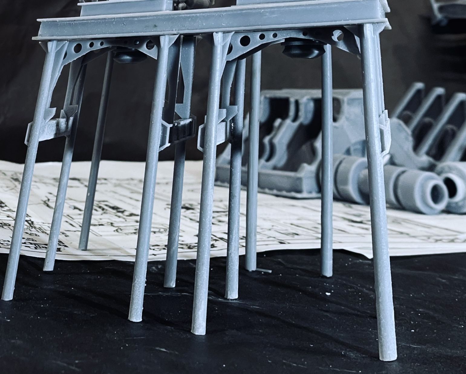
Here’s the sub-frame on the legs. One of the legs wasn’t in full contact with the cross-beam on the drawing and printed as a separate part. i put it on after fitting the pieces into the sub-frame to insure that its alignment was correct. I fastened it with Bondic AND CA. You will notice that the arm on the relief valve is missing on the TG in the foreground. It wasn’t the only thing wrong with these prints. The steam throttle body wasn’t attached to anything being held just by the two pipes, and the gauge panel suffered from the same malady due to forgetting to draw the attachment. I printed a spacer set for the throttles and new gauge panels. I attempted to glue all this together with CA. It didn’t look very good. Then I broke off that little arm. I really liked that detail since it printed so beautifully. The result: I reprinted both of them. Once I know something this important isn’t right and I have the time and resin to do it over, I will do it over. Visitors to the ship have no idea that these machines are suspended on legs so far above the hold. Seeing this model, they will understand it.

Looking up into the supports you see the nice perforated cross-piece. This stuff was almost impossible to photograph in the 1:1 ship, that no one, and I mean no one will be able to discerne that this is either realistic or not. Modeler’s license.

I’m working on the evaporators. These are only located in ER #3. There are three heat vessels. The left end takes in seawater, boils it. It’s steam goes to the middle where is condensed with some condensate being removed and the remainder reboiled again with its steam going to the last vessel and it happens again. The output of the middle vessel produces potible water for crew, the 3rd produces feedwater for the boilers. In other words, the boilers get better water than the crew. I don’t have detailed drawings of these, and my photos only show the front faces, I don’t know where the piping goes when leaving the evaporators. I do know that the feedwater is stored in tankage in the walls of the ship immediately behind these units. Remmber, there are 20 feet of voids, tanks and armor between the engine room’s walls and the ship’s exterior.

Lastly, I’ve redrawn the growing overall project image with the new acrylic bulkheads. This is a better solution that the cutaway slivers that I was originally thinking about.

I’ve completed the print files for the floor grating. I still don’t know how many gratings I will install. They form all the working decks that separate the levels within the engine rooms. Install too many and views will be blocked, but none will give the illusion that people work on montrous machines that tower over their heads. They are supported by angle-iron frames that are very frail in 1:48 scale. I suppose I could print the grating with its supporting angle iron framing. I will see if I can old-school cobble the frames out of styrene shapes. If it’s too ridiculous I will use the printer.

I looking at that picture, I’m thinking the bulkheads could actually form the display case… Hmmm. The shafts would protrude, but that may add interest. Otherwise, you’ll have acrylic walls surrounded by more acrylic. We’lll see. Posting helps me think…

7 Likes

Your attention to detail and desire to educate… Excellent!

@mmarcovitch Hi Miles, If you havent figured out Vray yet here is the reply I received. I have not tried it yet so I cant say its a fix but its what Chaos Tech Support sent me.

Please follow the steps to reset your localhost Chaos License Server
I attach an image that shows how to find, stop and start Chaos License Server.
1.Please Stop Chaos License Server

2.Important: Please delete ssl folder , which you will find here %appdata%\Chaos\VRLService

3.Please Start Chaos License Server

Then please open in browser http://127.0.0.1:30304/ and make sure you are logged in.
Restart CAD software and check if our plugin works.

If the licensing still does not work, send back to us:

  • a full-page screenshot of http://127.0.0.1:30304/ opened in your browser.
  • attach folder logs located in %appdata%\Chaos\VRLService\
  • send vrlclient.xmlthat you will find in: C:\Program Files\Common Files\ChaosGroup\
  • Please enter the command below in Powershell to check if a valid UUID (Universally Unique Identifier) is returned and send us a full-page screenshot.
    Get-WmiObject Win32_ComputerSystemProduct | Select-Object -ExpandProperty UUID

Thank you… I appreciate positive feedback. It keeps me going.

I got V-Ray to work by starting a trial and loading the brand new update that is apparently ported for SU 2025. Now all I have to do is make sure I’m not billed for the update since my SU Studio license includes V-ray. The update works well.

Well… printing the condensers has been a bit of a challenge. Yesterday’s print failed at 47%. We were out to dinner when the printer stopped. I rebooted it and it asked if I wanted to continue the paused print. I said “Yes”, it stated printing, but when I went down to see it, the print looked like this:

And PAF film at the resin vat’s bottom.

After popping the cured resin off the film, and futher inspection, it looked like a good time to change it out. I was at 47,000 layers when the job started. Changing out the film is not hard, but it is a bit time consuming. There are two layers of screws. First to fasten the entire frame into the vat body, and then 28 smaller screws to fasten the two halves of the sealing frame together. This view shows the new film in place and the film frame fastened into the vat frame.

Here’s the screws removed to release the old film.

The new film seemed to work and I finally got a perfect print of the TG condensers. It’s the weekend so I won’t be in the shop. I will clean these up on Monday. Here they are in the draining fixture. By letting the excess resin simply drain off greatly reduces the resin loading in the alcohol wash and saves expensive resin.

I also got the sub-frame and evaporators finish designed and built the first ladder on the specifics of this particular ladder based on the ladder detail drawings I have. They’re all different and all identified. I put in a smattering of floor gratings. I’m going to print a bunch of these so I’ll be able to put them where they do the most good. The evaporators are also supported on columns just as the turbogerators are.

7 Likes

Just because it’s Saturday doesn’t mean that stuff isn’t geting done. Besides some exercising I worked on creating correctly sized and detailed ladders, started placing ladders and floor grating into perspective places. I also applied steam lines to the main condensate pump. Yesterday I added the steam lines to the turbogenerators. Gratings won’t hide too much detail, nor will the minimalist piping that I’m including. The grating supports on the lower level are pretty close to prototype. I haven’t decided how to support the upper gratings. I will have to study the drawings and photos to figure it all out.

The steam inlet to the pump has to come off the main steam pipe, but I’m really not sure how all these pipes do that. My photos are totally confusing, so I’m taking modeler’s license to put them where they make sense to me. I do know that every piece of equipment has a steam input and a discharge that has to go to a condenser. For the discharge of the pump, the only place to tie into a condenser was (I thought) would be into one of the TG condensers and ran a pipe to it.

Then…. while looking at this image and writing this post, I realized that there’s a pipe stub sticking out of the main condenser that—most likely—was actually the place where this condensate line would enter. So I re-routed the line to this stub and it makes a lot more sense. You’d be surprised how many insights I get when writing all this stuff.

​Lots of things to print. I’ve started printing the piping. I have to design and print the two lubricant pumps (one electric and one steam turbine), one large and two small air ejectors that removed dissolved gases from condensate before it goes into the boilers as feedwater, and the electrical cabinets and two control panels. None of these are big or show stoppers.

6 Likes

Thanks gents!

I’m reprinting one of the TG condenser frames due to a leg breakage and the one that I had to glue on. It was time to just redo it. All it costs is some time and resin. Meanwhiile I fiddled with the opening in the condensers to accept the large exhaust flange. The hole needed to be englarged a bit so nothing had to be forced. Getting this all to fit together and stay together is not a given.

It was a gorgeous day here in Louisville topping out in the mid-70s (F) and with a slight breeze. I took advantage of this and started some of the solvent-based painting. I got the turbine rotors and MRG gears painting with Humbrel spray chrome. It’s a very nice, bright metallic paint. I also painted the bull gear. I was going to start doing all the primer painting of all the other parts now printed, but a lot of them had to be touched up with sanding and cleaning, and I was running out of time and didn’t want to rush it. I make bad mistakes when I rush. The gears look pretty good and will look even better when in the gear box. Speaking of which, I’m working on getting the main parts to fit better and preparing for the assembly screws before any painting.

I still find it hard to believe that I drew and printed those gears…

I spent the rest of the workshop time working over the piping and getting them converted for printing. I’ve also set up for printing of the “angle iron” frames that support the floor gratings. I’m printing a bunch of each type and size. I got the ladders ready for printing as well. Parts count is rising! I have to study how the upper floor gratings are supported. There is a mezanine level on the port side wall that holds all the electrical cabinets and the electrical distribution control panel. None of this is complicated, but it has a flooring frame and lots of gratings.

I’m holding off on designing the main control panel. In 1:48, my ability to do decal faces is difficult. I can produce them on clear background paper and paint the gauge faces white before application. That simplifies the process. And I just thought of it while writing the last sentence. I need Ryan to get me some good images of the panel that I can use.

6 Likes

Wow, those gears look like metal! When I first saw the photograph I thought “why is there a photo of machined metal parts here?” Well done.

5 Likes

Thanks Tom! Wait till you see how the printer reproduced a very good floor grating…

Printing lots of stuff. Had a pipe print failure due to insufficient support strength. Will reprint with changes. Printed a gaggle of flooring frames and even more walkway gratings. When I decided to undertake this massive project, one of my main decision points was if I could print respeactable floor gratings. The new printer produced stunning gratings that eliminate the need to create these kinds of things using photoetched. They are ephemeral and very fragile, but when glued to the floor frames they will hold up nicely. I finished the turbogerator condensers with most of their piping. On the printer right now are all the ladders needed in this space. There are five different varieties.

First the condensers.

I pre-located the drill holes in the drawings and subsequent printings, so the holes just had to be opened up to 1/16". A piece of 1**/**16" brass tubing made a very secure connection with CA adhesive.

Here are the condensers with all minus two pipes.

I printed a bunch of single and double floor frames. There’s one leg that I designed without enough integration and it’s not very strong. I reinforced its interior with Bondic making it more secure.

I also have a ton of worthy floor gratings. Took close to an hour to carefully separate them from their support system. This new printer will reproduce just about anything.

Some of the bars are damaged on the edges, but they’re bigger than the frames. When trimmed they loo pretty darn good if I do say so myself. When painted oxide red they will be great.

And they look great (no pun intended) from above being almost transparent due to the thin bars.

​I’m designing the lube pumps. There are two: one electric powered that was installed in the 1980s refit, and the other steam turbine driven that appears to be the original design. When I dropped their foundations into the master drawing, I was concered that there seemed to be no room to move around them. I remember walking next to the pumps with lots of room. Did I make a scaling error?

Nope!

Based on this analysis, the configuration of the equipment in ER #2—the one open to the public—and ER #3 shows very little clearance around the pumps in the one I’m doing. It’s the position of the MRG in #2 driving an outboard properller shaft #4 and ER#3 driving an inboard shaft #2. Shafts are numnbered from startboard to port, whereas engine rooms are numbered from fore to aft. The drawing tells the story. Notice that the ladder to the upper lever is very tightly fitted, versus the wide-open-spaces in ER#2.

In this picture that Er#2 roominss is on full display. That space does not exist in ER #3. That old dude walking is me…

So I will be trued to the plans a shoehorn the pumps into their repestive spaces. Onward and upward.

6 Likes

Amazing progress :clap:

Thank you!

The ladders came out as nice as the gratings did… maybe better. Here’s some pictures that show. The stair railings are only 0.020" or about 1 scale inch. Actually scale! By not curing the resin more than 3 minutes and with my resin blend, the railings still have a lot of sprint to them. You can bump them without breakage.

​Below: this was before I did some very delicate sanding to remove the slight support nubs that remained.

This is the five step stair.

And I threw some grating next to the tgs just to see how it looked.

Gratings was one of the things I thought about when I decided to build this ridiculous project.

I’m continuing work on the lube pumps. Don’t have any good drawings of these so I’m working only from photos. Electric pump is one the left and steam turbine pump on right. Steam pump is OEM from 1943. Electric was swapped in 1980s refit. Steam piping is complex and I’m trying to interpret. Couldn’t get close to them in ER #3. Work platform grating is where the legs top out. The legs rest on the 3rd bottom (hold floor). Still have to fit them between the main reduction gear supports. Probably will need to modify.

This is what I’m talking about… it would be a bit easier if it wasn’t for all the insulation.

4 Likes