![]() just keeps getting better !
just keeps getting better !
Thanks, I sure hope so…
I brought the kit home and finally had the chance to see just how off my drawings were. To my surprise, they aren’t too bad. The main error was the overall turret plan shape. The model turret was a tad (.08" narrower), but different in length by more and the angularity of my drawing was a bit different. All in all, really close. All the apparatus I’ve designed so far will fit as it is.
The kit’s bottom plate, besides not actually being an accurate floor, has a huge opening in the middle which must be closed. The only holes in the turret floor are the rectangular openings for the gun’s motion (elevation and recoil), the chases for the powder and projectile hoists.
I measured the circular opening, downloaded what I already had from SketchUp since the openings in the floor were set by the gun’s design, and drew the filler piece to close the hole. The hole is rimmed by a 1/16" ledge, so I will either have to get some 1/16" styrene sheet or double it up. I may choose to make the floor and filler pieces out of transparent stock so you can view what’s below, but there’s some much stuff on the gun room floor you won’t see much that way.

It’s not full circle with parts cut off with some angles, but that’s not a problem.
Here’s how the template fits into the hole. Notice how the gun slots are going to be outside the circle meaning I will have to cut the kit part. I may also have to shorten the slot’s length so it stays within the turret’s perimeter. The front gun shield swings down into that space so I have to watch the clearances.

Over this filler will go another flat sheet to provide a smooth floor surface for the entire gun house. This too was created by measuring the space and then printing, adjusting and printing again. It’s really nice to have the kit!!

Notice that I’m making it in two parts since the turret’s rear has a kickup angle. I supposed I could scribe and bend the styrene to make the angle. In fact, as I’m writing this, I’m thinking that could be better.
With the actual turning circle in hand, I was able to start finalizing critical parts for 3D printing. I can’t print the entire lower bearing race and traverse gear as a single part, or even a half, but I can print it in quarters. I devided it up and provided assembly keys so it goes back together properly. I’ve recently tried this technique on another long part and it works. I have a software add-in that lets me intersect one object with another an remove material with a mouse click. It worked well in creating the negative space for the keys to engage. This ring and race is a critical component of the finished model.

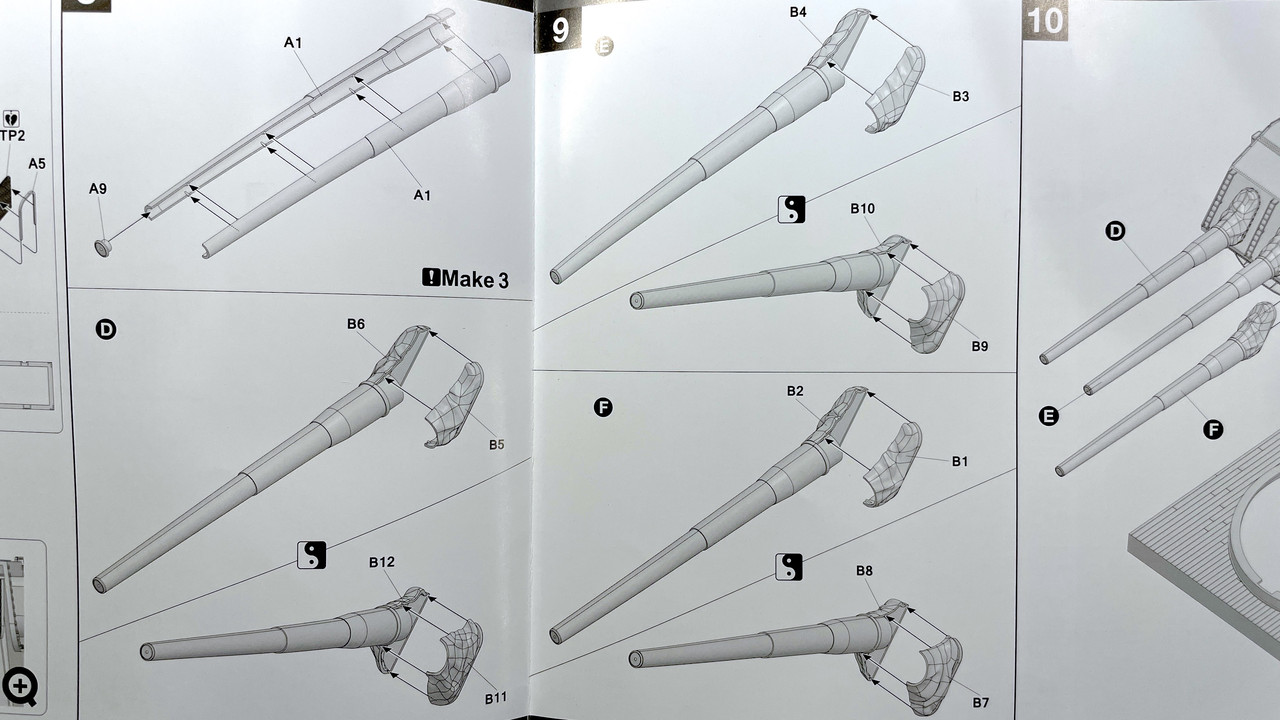
The gun bloomers from the kit are a two-part plastic affair. They come in an depressed and an elevated style. The kit guns glue directly into them. My guns theoretically will be movable, if I can make flexible bloomers. It’s one thing to make them look real, but quite another to make them look real and flex.
This is how the kit shows the guns going in. Obviously, with a fully detailed gun behind the bloomer, the kit method will not work.
Here are the bloomer parts on the sprue.

So I woke up this morning working out a method of making a flexible bloomer for this important model. My first thoughts were assemble the kit parts and coat the outside with silicone mold material in a few thin layers, but the color is wrong and nothing sticks to the silicone, especially paint. Then I thought of using Liquid Electrical Tape which is a fluidized vinyl material that is already black and flexible. I thought again of assmbling the bloomer pairs and coating them with this material, but am concerned that the solvent in the liquid tape would not be compatible with the styene.
So I ended my mind experiment by using the silicone material to make a female mold of the assembled bloomer and pouring the liquid tape into the mold, pouring it out again so the material coats the interior, letting it cure and doing it a couple more times to build up the thickness. This would form a hollowed out perfect replica of the kit bloomer, but it could also flex depending how I can control the thickness. it will be an experiment.
Lastly, I found the metal gun barrels on eBay, directed to me by one my blog readers, and ordered a set for me and two more for the hobby shop as requested by the owner. There was significant price break at three items. They’re coming from China with free shipping. The three-item price was $11.89. I really didn’t want to mess with the styrene guns. I did use the kit guns to refine the opening diameter in the slide assembly that I’ve drawn. The beauty of the metal barrels is already having a real metal finish on the exposed slide area. The guns are greased at that junction and I will have to simulate this on the bright aluminum.

The more I do on this project the more challenging it’s becoming. There are lots of variables to manage with many part interactions.
5 Likes
I just got a new Elegoo Mars 3. It’s 4X faster than my Mars “Classic” with about 30% more build volume from a slightly larger build area and more depth. It has a 4K monochromatic LCD in comparison to a 2k standard screen, so the horizontal resolution now is almost as good as the 10 micron vertical. I will use the old one for the thinner and less critical jobs.

It couldn’t have some at a better time as I’ve already put it into service printing critical parts for the turret project. The larger build space is already paying dividends printing the entire officer’s compartment floor plus the rammers attached in one piece. This greatly simplifies final assembly. I did a test print of the entire rear bulkhead, but it had a couple of errors (the drawing, not the machine) where the porthole lids delaminated from the surface. Cause? The two outer ones weren’t actually sitting on the surface. Printing doesn’t work on disconnected surfaces.
Here’s the set up for the entire officer’s compartment floor. I will print this on Monday. This would be a 20 hour print on my old machine, but now, at 2.5 seconds/layer, is about four hours.

I’ve also set up the ring gear segments for printing, two per load. I’ve fixed the bulkhead drawing and will reprint. I also set up all the rollers for printing. I woke up thinking about how to construct the working roller ring without going nuts.
I’m also laying out all the flat parts that will be fabricated out of sheet styrene. While I’m doing that I’m also thinking if any (all) qualify for laser cutting. I have access to the Makery at University of Louisville, but it has limited public open times and you need to reserve it ahead of time.
3 Likes
With the new printer’s enhanced capabilities, I was able to get a perfect print of the entire officer’s compartment floor including the steps and all three ramming machines. This solved a huge assembly problem. In the prototype the floor panels are removable and wrap around the rammers. With the single print, I was able to simulate this. I’ve also included all elevating feet that hold it up.

Now all I have to do is remove that forrest of supports and post-cure it. Remember, prints just out of the machine are not fully cured. If they were, each layer couldn’t bond to the next. Some supports will be easier to remove in the soft state, others are better when hardened so the grinding burr works better. I’ve gotten pretty good at removing supports without damaging the part.
I also successfully printed and entire half of the rangefinder with all the attached things on it. It’s being cleaned now and the other half is in the printer. And I’ve designed the entire gun girder assembly includng the manual sighting stations and the powder hoist machinery as a single part. This JUST fits into my machine. It’s not the ideal angle for printing and may not be successful since it’s worth a try.
Here’s the drawing,

And here’s how it’s going to work in the printer. This is the slicer image. Remember; it prints upside down. I hollowed out the underside of the girders to reduce the amount of resin used, and the amount of resin in contact with the teflon seal.

The pink areas are parts of the base that extend past the machine’s limits. That doesn’t matter as long as none of the actual part are that color. I had to keep rotating in three axes to get it so it would all fit.
Here are the two parts of the rangefinder as they were on the printer. The detail is fabuloous. That gear rack is perfectly formed. This is the one that already printed. It’s the longer of the two parts and since it was so perfect, I’m sure the shorter one will be too. You can see the assembly keys that will ensure that the two parts mate correctly.

And the shorter part: Note that the seats and handwheels are all there. They’re going to be very delicate.

I downloaded dozens of new images from the Naval 16" 50 Cal turret operators manual, including things like these that I used to draw the manual sighting station equipement.

And this one that shows the cable hoist for the powder hoist system.

None of these images have any scale attached to them, so I have to constantly wing it, but the main thing is to ensure that it fits into the space allotted. I based the manual sighting stations on the spacing as they appear coming out of the turret sides. I may be wrong and if so would trim them off and just reprint the equipment, not the entire gun girder part.
My tour of the USS NJ is schedule for May 12. I will have a lot done by then. If the gun girder print is successful, I may use this method for the pan deck, electric deck and projectile flat printed with all the equipment already in place. It will greatly reduce gluing challenges.
As I’ve many times before, with a good 3D printer, a graphics program like SketchUp, and some computer graphics skills, If I can draw it I can make it.
In studying the manual deeply, I am still blown away by the sophistication and complication of the electro-hydraulc systems used to make a turret of this size work. Add to that the quadruple redundancy in making it work. In addition to the firing triggers in the plotting rooms (Two of them). Each manual sighting station had a firing trigger on their handwheels so the gun could be fired even if all of the other systems were out of commission.
Update:
The floor printed pretty well. It will need a touch of massaging to fit the plastic turret’s floor, but it will work. The left half of the RF printed very well, although I broke off one of the crew seats in getting off the supports. Actually, I thought all the supports were disconnected and pulled off the bunch, pulling off the seat and its bracket since the supports were still attached to it. The right half of the RF failed halfway through when the supports broke. I inadvertantly used Light Supports instead of Heavy and they’re just not up to the job. I genearlly use Heavy all the time and then go back and edit them in areas where there are fragile components and use light or medium supports. I’ve redone the support set up and will reprint tomorrow. I will glue the broken seat back on and may reinforce with some fine wire. Bondic joins to UV resin like crazy since it’s basically the same material and therefore is welding.

I need to double check the spacing of the two pointer and trainer telescopes compared to the openings in the plastic turret shell. This needs to be done BEFORE I spend the time and resin to print that large gun girder piece.
4 Likes
Lovely work and I enjoy reading your descriptions. I hope your tour of the actual battleship will be fantastic.
I suggest making a list before hand of the reference photographs or meaurements that you want to take, and consulting the list on-site to maximize your time and reduce the chance of forgetting something important (everything is important). ![]() I have done a number of research trips to study artifacts in my area of interest. I prepare paper sheets similar to the following for the features that I want to measure:
I have done a number of research trips to study artifacts in my area of interest. I prepare paper sheets similar to the following for the features that I want to measure:

The base image consists of photos that I’ve taken previously and processed to bring out edge detail, leaving most of the image area very light for making legible notes. The pencil marks represent features that I want to measure, with the red circles waiting to be filled in with dimensions on-site. A quick scan during the visit over the printed sheet looking for empty circles will indicate if I’ve forgotten to measure something that I had planned.
I would love to measure many more features, but with typically a limited time budget (imposing on museum staff etc.) I try to maximize the value for time.
2 Likes
Impressive stuff!
There is something about 3D printing it, that may not have occurred to you, so I will mention it, and apologies if there is something I’m missing.
Taking this as an example, if you rotated it to be vertical, and rotated it 90 degrees so that the right side is now flat on the ground, you ought to be able to print it with almost no supports.
Rotating it counterclockwise might be even better, then there would be less supports for the guns (if that’s what they are).
1 Like
Good idea about preparation before the visit. I was planning on taking a tape measure with me for that purpose, but the sketching is something I have to add.
Re: the new position on the printer. With the sighting stations attached the model hangs over the edge. That said, I may want to leave them on and glue on later since they must exit through a specific point in the turret wall. I can fit it (Barely) with those removed and I may be able to attach the gun lugs to the print which could be beneficial. In order to get the guns installed. To effect that I would split the caps on the lugs, drop the gun trunions into the lug and replace the cap. I may leave the hoists off too since their placement is still a bit ambiguous.

1 Like
I really wanted to set it up as Colin suggested so I made some more changes. I removed the sighting stations and hoists. The stations were wrong anyway. I meausred the spacing of the sight locations on the plastic turret and they were not correct. I re-drew them to match the spacing. I then added the gun lugs to the girders. I had to re-check everything. The lug bores were quite wrong, and not in line or spaced correctly. So I re-measured the guns’ trunions diameter and the the exact width from the thrust surfaces and modified the lugs to match. I then split the lugs (prototypically… I might add) to create a removable cap to allow the guns to be lowered into the lugs. With the lugs embedded in the girders (again like the real ones) I couldn’t get the guns in since nothing would move.
Here’s the new scheme. The only required supports are for the horizontal surfaces that would not form properly with the reinforcement.

Here’s the printing scheme for the equipment I removed from the gun girder assembly.

I re-printed successfully the back bulkhead and re-printing the failed short half of the rangefinder. That’s going to done in a half hour.
1 Like
@mmarcovitch perhaps you should consider editing the title of this thread. While very interesting, and I hope you continue posting your progress, I don’t think you need much help at this point.
Keep up the good work.
Shep
3 Likes
That’s a good suggestion. Change Made!
Printed the remainder of the gun house details (well almost…). Got the rangefinder assembled and test fit on the officer’s compartment flooring. I will have to make some adjustments and will reprint the floor. That’s the trouble of building everything by eye without actual dimensions. But hey, all I have to do is change the drawings and print again. Got the hoists, sighting systems, gun lug caps, turret computer and communications panels including the switch matrix.
I’m using ChiTuBox Pro for the first time. It has many more features than the basic (free) program. A one-year license came with the printer. It has a “REPAIR” feature that lets you fix errors in the STL file. I tried it out on one version and uncorrected on the other. The “repair” closed off areas that were supposed to be kept open. The arrows show this.

I’m not going to use the repair function very often.
Here’s the finished Rangefinder. The joint worked pretty well and enabled me to put the two halves together in pretty good registration. I had to trim the floor to get it into place. I will reprint the floor with the proper clearances.

And from the top;

The apparatus prints are excellent! Everything shows up.
Here’s the manual sighting station. Note that the handgrips on the hand wheels were reproduced.

The trunion caps and hoists also printed accurately.

The officer compartment computer station is especially rewarding since all the hand knobs clearly printed including the indentations around their perimeter. My method of supports is to use all heavy supports, then go back and delete those on small, fragile and/or areas at the top of the model where the stresses would be less. I then replaced these with precisely placed at the same locations. This works.

Lastly here’s the communication and switch panel. I produced these as a linked single part to make their installation easier. Of of this will look pretty good once painted.

The full gun girder part is printing now. It will be a 9 hour print in the new machine. In the old one, it would be over 30 hours and wouldn’t fit anyway. Y’all will see if it’s successful tomorrow.
5 Likes
Repair options in Slicer software are usually there for beginner users with limited drawing skills. (who make mistakes like not moddeling correct solids for instance)
If your drawings are good and clean solids you wouldn’t need them and as you found out the repair options do make mistakes as they often have to “decide” whether the modeller made a mistake or did something on purpose…
By seeing your results, I guess your skills are well above average!!
Keep up the good work!
The detail is stunning ! ![]()
Thank you! Yes… I work my drawings to death to ensure everything is solid and normal-faced. I also spend a lot of time making sure that nothing is free-standing. I find that downloaded drawings from the Warehouse often are drawn with surfaces that have no depth and are therefore unprintable. It takes a lot of time to alter them to be usable.
My idea to print the entire gun girder with the gun trunion lugs as a singe piece was successful! I could not have achieved this had the new printer not arrived. it’s larger capacity and resolution are making all of this possible. My first thoughts were to build the girders out of assembled styrene pieces. I wasn’t looking forward to that since keeping the geometry tight would be challenging.
This was the massive print as it came off the machine. Notice, the only supports were to allow the horizontal surfaces to print.

It was almost too big for my cleaning system. I had to use a paint brush to wash off the resin with the IPA, and then do it two times in the ultrasonic cleaner, turning it end-for-end so the whole thing would get cleaned. Here it is with the supports removed and sanded. I do the sanding AFTER post-curing it in the UV chamber. That too has a size limitation. I have to keep all this in mind if I ever want to got further up in printer sizes. They’re getting much larger with the addition of the Elegoo Saturn and Jupiter lines. I thought ahead and made rabbets where the styrene partitions will sit. This will add addition gluing surface for these vertical and thin parts. I adjusted the height of the part to accomodate the 1/8" deep rabbet.

The trunion bores are perfectly in line. I recently came to the realization that making the guns able to elevate is moot. Only one gun will be able to move… the one with the cradle/span tray in the retracted firing position. The other two guns in the loading position will have their spanning trays protruding into their breaches. If you attempt to move the gun you will break the cradle assembly.
Here are all the small parts going into the turret gun house. They are sitting in the UV curing box waiting to be hardened. I was rewarded when trial fitting the manual sighting equipment into the gun house plastic part that it fit perfectly. The tiny crew seats were very delicate and I broke of two. One I glued back with Bondic. The other disappeared and I’m re-creating it with Bondic also.

Then I ran into another challenge. The full-length rangefinder can’t be installed into the gun house part! To install it so it protrudes out of both RF extensions I would have to cut the gun house to open the existing holes to the bottom edge.

There’s always another way, and the solution actually is better. I re-drew the entire assembly, fixing all the probems I had with the flooring and the RF fit, and created as single part print. Then I split the RF just outside the supports on each end. These parts can now be installed from the outside AFTER the gun house is assembled.

I keyed the two extensions so there’s no chance to mix them up. The print, like the gun girders, is massive for my system and, also like the gun girder, just barely fit the cleaning stations. The print has lots of suppots! I noticed some stress cracking due to some shrinkage, but they’re fixable with Bondic. There’s also some minor imperfections in the area where the previous RF tube joint was. With this method I am assured that the RF is perfectly in line X-Y and Z directions and solves another assembly challenge.

Here are the RF optic tips after cleaning and before post-cure. I also fixed their geometry. They are keyed so they can’t be mixed up. BTW: the RF/Floor is also in the raw state. Easier to remove supports when they’re slightly soft.

Just to be sure I just trial fit the new RF assembly into the turret gun house and it fits just fine.
Right now I’m finishing the drawings for the cradle-area sub-assembly of the gun compartment. There are still some gun house details that I’ve been overlooking. These include the ventilation system and all the electrical boxes and cabling that line the gun house walls. I’ve incorporated them into the rear bulkhead, but not the rear gun house wall. I don’t have a good image of the layout… just little snippets.
I’ve pretty much finished the pan floor detailing and will start printing that next week. That leaves the complex electric deck and the projectile flats. The powder handling spaces are not particularly interesting with some concentric spaces where powder bags are transferred from the magazine outside the barbette into the central rotation space where the powder hoists are.
5 Likes
With new information from a Fine Scale Modeler Forum reader, I just worked for four hours revising the drawings of the gun girders, read bulkhead and the officer’s compartment floor system. The actual gun center-to-center distance is 10’‘-2". My gun spacing measured to 9’ 5". While I regretted having to do this, it solved a nagging problem I was having: “Why were the access doors in the rear bulkhead unable to line up with the gun compartments?” That difference stacked up and made everything out of alignment. I believe it’s fixed now and will reprint the whole deal. They’re big parts and take a bit of resin, but it’s worth it. All of the other dimensions of the gun house itself are fixed by the Takom Model. When I held the gun girder print up against the openings in the gun house glacis panel, the gun centers DID NOT ALIGN. The Takom part is correct. My intial parts were wrong. I set the gun distance by building them over the drawing of the turret plan. I don’t know how accurate that drawing was. I should have used the plastic part for the gun centering regardless of what my drawing was showing. My part HAVE TO FIT the plastic model’s parameters.
That said, the parts I did print really looked good. I’ve also revised the rear portion of the officer’s compartment floor in the re-design to give more leg room under the rangefinder operators. Each change I make at this point creates a whole lot of work. Example: to move the door spacing in the rear bulkhead I struggled far too long trying to close the surfaces and cut new through-holes for the door and wall port holes. I finally relized I was wasting my time and just erased the entire wall and redrew it fresh, thereby eliminating all the remnants of the previous locations. Took much less time. Repairing in SketchUp is often very frustrating.


And just to give you an idea of how much work it is to remove all the supports without breaking any details, here’s what’s left after about an hour’s work. The building in the background is the next one I’m building for the railroad.

And here’s all the details underneath that wil be out of sight in the finished model. Some of this has changed with the new design. I’ll print that tomorrow.

And look what else came in the mail yesterday… I was expecting this stuff to arrive in weeks. It came much faster. So I was able to get a good fix on the diameter I needed to fit the guns to the slide assemblies. I set both the closed and open-breached versions up for printing. Lots of printing over the next couple of days.

The only thing I don’t like about the guns is the bore opening does not go in very far. I will live with it. I have a lathe, but chucking up tapered parts is tricky and I don’t think it will be worth the effect. The risk is too high.
6 Likes
I love seeing your progress, thanks again for the updates.
I guess your goal is to conform to the model kit’s parts and dimensions. That’s fine. However, I would not be shocked if the kit’s dimensions are wrong themselves (maybe only a little, maybe a lot). The kit designers were surely under time pressure to make a nice-looking model and were not passionate about maintaining a high degree of accuracy.
I think the kit’s pretty close. I’m going to have to open the gun slots just a skosh so my gun slides will fit through.
The change of that 10’-2" center distance, cost me about 5 hours of drawing work. It changed a lot and solved some problems too. I successfully printed the first gun assembly, but had warpage. The fit of the metal barel into the slide was perfect, but the gun isn’t pointing straight.


Amazingly, the printer reproduced the hand grabs on the counter-recoil covers. The breach details came out okay too, but I went back and added some meat to the t-handle used to lift the breach to closing position.
From the side, it all looks pretty good. But from the top, it’s another story.


The twist seems to start in the trunion area and continues into the slide area. I also used the hollow out feature of my printer’s slicer program to reduce some of the resin use, but I didn’t like the results and it may have contributed to the warp. I’m correcting this by printing the gun in three parts: two slide halves and a single piece breach yoke. I’m screwing the two halves together with 4 X 10mm screws and nuts. Overkill, but i had them around. I will plug the holes with custom-printed plugs. Here’s what it all looked like. This took a lot of hours to do too. All day yesterday. Splitting the drawing was easy, closing off the back of these complex shapes to make them a printable solid took hours.

I re-printed the rear bulkhead with the new door spacing. Again, I used the reprint as a chance to fix some of the slight dimensional errors I had.
I also got a successful print of all four of the traverse gear rack ring and lower roller race.

And yes, I’m trying to include as much detail as is physcially and practicably possible in 1/72. So keep all the input and thoughts coming. I’m listening.
5 Likes
Just had a small shock! All of a sudden every model on the Trimble 3D Warehouse is restricted to Ver 2019 and later. That has just blocked every model to my Make 2017 version. Not happy. I don’t make money on SU so I really can’t justify the Pro version and the new on line free versions don’t give me the opportunity to do the complex work I’m doing. Any ideas?
The ring gear assembly test was successful. I pushed the segments together, but not fully seated. There was some warpage with the curve of each segment tightening. I’ve given up the thoughts of having this beast actually rotate since all the cutaways would be out of sync, so if it’s a little out of round, I can probably live with that. And like an idiot I sanded both running surfaces before assembling and sanded off those nice raised lettering that identified the assembly sequence. I was still able to puzzle it together by looking how the gear teeth were split. None were segmented in the same way making them unique.

The gun slide was another thing entirely. While the print was successful (sort of) it still warped a lot. Both halves warped away from the jointing surface at each end. I thinned the slide sleeve that was to accept the gun to much. I did this so it would slip into the slots on the glacis plate on the gun house. So it kind of fell apart when I post-cured it. I screwed it together tightly using the two screws by design and another 1/4-20 bolt and nut through the trunnion hole.
You can see the warp on the right side. That one doesn’t bother me becasue that hexagonal shape is going to slip into a corresponding hole in the breach block.

This sleeve problem required a more drastic solution. I turned down the tail on one of th guns to 7/16", narrowed the outer walls a bit more so the sleeve with fit through the .457" opening in the gun house and still give me more wall thickness so it would be stable.
I wasn’t sure I could chuck the tapered barrel into my little Taig micro-lathe. The spindle through-hole is not large enough to accept the hole barrel up to the parallel part at the slide area, but i was able to center it with the four-jaw independent chuck and use a steady rest to support the long overhanging part. I got the concentricity within a couple thou. I wrapped the chuck area with some adhesive label paper to protect the finished surface. I was able to successfully change the diameter. If my lathe was a little bit longer I could further drill out the bore, but it ain’t, so I won’t.

Here’s the turned down barrel. I’m not worried about the wear that the steady rest applied to the slide area. I will work that out. Actually the slide wear line go fore and aft not radially.

Here’s the reviseed design. The new design also gave me a chance to fix some drawing errors that were causing some print errors. You can see the thicker walls around the barrel entrance.

Jim Palmer, one of my faithful followers, has provided me some exceptional drawings (not SketchUp) based on actual engineering drawings of some of the critical structural areas that are very ambiguous on the illustrations that I have. He’s going to get me some dimensions to make these more usable to me. One of the big “AHA’s” was the edges of the gun girders form the partition plates in the pan deck. I can make this modification. I just need some measurements to firm up the final shapes.
I haven’t re-printed the revised gun girders so I can simply change the notches for the styrene plates so they’ll be the full depth.

Here also detailed the pan deck floor showing the exactly location of the gun pits and the various hatches used to get from one place to another. You can only actually enter the rotating parts of the turret in two places: the hatches underneath the gun house from the main deck, or entry through the powder flats at the turret bottom. All other access is by vertical ladders and quite small hatches. For these reasons I’m seriously wondering if I’m going to physically be able to go through all these spaces. Noticce the two outer access hatches are actually in the gun pits themselves.

What’s even worse is the electric deck.
The Electric Deck is fully partitioned and you can’t get from one partition to the other. You must go either up or down and then across. It’s like the Super Mario Brothers game. Luckily, I have done nothing on this deck except the outer walls so I didn’t waste any effort. And then there’s “how to show this interior?” There are four work stations in these partitions: one person manning the manual training (traverse) station, and one each manning the manual pointing (elevation) stations. It must have been pretty longer in those claustrophbic work stations in the bowels of the turret. All of this deck and the pan deck rotations with the gun house and the guns. When you get to the projectile decks, the outer portion is fixed. The next ring with the projectile hoists rotates with the turret sicne the hoist chases are fixed in their position to the gun compartments, and the inner ring is rotated independently with it’s own power system and circlar rack and pinions… sort of miniaturized version that rotates the turret itself.

I finally figured out how the projectile hoist actually works. It was somewhat difficult (for me) to puzzle it out since I was expecting an elevator arrangement like the powder hoist. But when you think about it, this wouldn’t be easy to do since the cradle that accepts the projecile is open at the top and there’s no cable pulling anything up.
Instead the mechanism consists of a moving rod that has spring-loaded pawls that engage under the forward side of the projectile’s bottom, and another series of spring-loaded pawls that pop out of the projectile hoist chase opposite to the moving rod.
The moving rod is stroked up and dow by a hydraulic cylinder (for those so inclined, the first part of this sentence did not talk about what you might have thought it was talking about). When the projectile is pulled into the hosit base via the par-buckling rope it passes through two spring loaded doors preventing the projectile from re-entering the projectile handling area. The hoist rod starts moving up with the spring-loaded pawl extended and it hooks under the projectile lifting it up the length of the piston stroke. As it reaches the top of the stroke the projectile has been passing by the pawl on the oppositie wall which pops out beneath the other side of the projectile’s bottom preventing it from falling back. The moving rod retracts downwards bringing the next pawl (retracte) along side the projectile where it pops out at the bottom grabbing the projectile and lifiting it the next stroke. This continues until the projectile enters the cradle which also has a pawl that snaps out grabbing the projectile and preventing it from falling back. The projectile is stable in this position and ready for loading the gun.
With this method, you can have more than one projectile on the lift at the same time. In fact, in order to load the gun every 30 seconds, you could not wait for a projectile to rise four decks and be ready to load. While not an actual drawing, this is my interpretation of how the pawls interact to move the projectile from the projectile flat to the cradle. The moving track is on the left. The pawls on the right are somehow fastened in pockets in the projectile hoist chase wall. That detail is not essential to understand the mechanics.

3 Likes
I have said many times before, I am not particularly patient, but I am persistent to a fault. And persistence what was called for in making a functional slide assembly. My fifth and sixth prints were completely successful. My fourth was a correct design, but I didn’t get it loaded correctly in the printer and part of it failed. On number five I let the printer slicer software (ChiTuBox Pro) auto-position the part on the platen.
It was a bit counter intuitive to hang it like this. Normally you set it at around 45 degrees to minimize the surface area on the plate to reduce the suction forces that tend to pull the part off the plate. In this case, vertical was the smaller foortprint and it left the delicate counter-recoil and gun captain platform basically without any supports at all. No supports is the best case scenario since supports cause potential surface defects.

I had to drill out one of the hollow access holes on the part to help clean out and drain any unexposed resin trapped inside. My slicer-drilled software hole wasn’t deep enough to connect with the hollow chamber. After drilling it into open space, I used a large syringe to flush alcohol through the insides and clean it out. I then put it in the ultrasound and afterwards used compressed air from one of my airbrushes to blow out the remaining liquid.
I machined the other two barrels down to 7/16" and now have three good, warp-free guns. it took a lot of trials and wasted resin, but without the guns the entire project was up for grabs. The guns are the essential focal point and are neat models all by themselves. All the gun point in the right direction… straight ahead.

The two guns with the open breach are right-side loaders and will be set at the 5° elevated load position. The remaining gun is a left-loader and will have the closed breach held in the 45° maximum elevated firing position.
The side of the gun is nice. The only details that got whacked were the tiny hand grabs. They had supports on them and removal of the supports broke off the handles. I’ll make new ones out of fine wire. I have plenty of rejects on which to try out making them.

The yoke with the open breach on the back of this gun is not perfect. I’ve printed three more after fixing the drawing. They’re done and hanging on the machine for clean up tomorrow. There were some improper faces on the bottom that failed to print. I found the errors and corrected them.

Work is continuing on the pan and electric decks. I’ve got the partitiions laid in on the electric deck. With the partitions in place I can start laying in the equipment. I’m also wrestling with the rear area of the gun compartments. There are lots of hydraulc controls on those walls for the cradle, the rammer and the gun captain’s communications devices.
6 Likes
I know basically nothing about 3D printing, but watching you develop your model and try out different printing techniques has been VERY informative and entertaining to me! I’m excited to see how it comes together!