From Xometry:
Thanks for reaching out. In general, we can work directly off of the CAD model when manufacturing sheet metal parts - we don’t need a fully dimensioned print. This is not always the case, but for this part I believe we would be able to work directly off the model.
As for your second point - you’ll have to specify what kind of tolerances you will require for the features in question. Our standard sheet metal tolerances are +/- 0.020. You can add specific tolerance requirements on the “Features” tab after you have uploaded your CAD model.
I didn’t quite get a clarification as to whether or not they need the radiused bends, but it doesn’t sound like they do. I took your model and reworked it for 0.0375" (20 gauge) and converted it to a FreeCAD shape. Then I exported it as a STEP file (not an IGES file, @sketch3d_de ![]() ). Here’s how it looks in A360:
). Here’s how it looks in A360:

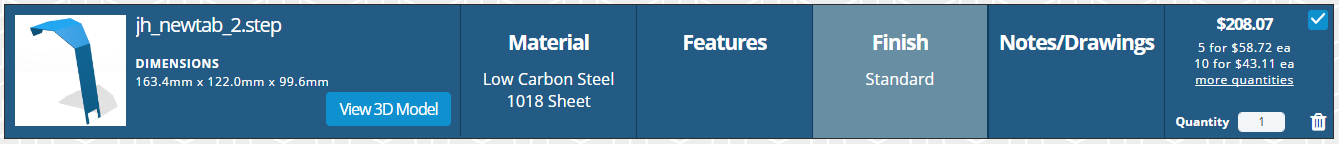
I uploaded it to Xometry and this is the result (kind of pricey, if you ask me):
I took the “underside” faces of your model and extruded them “upwards” 0.0375" and then connected the corners and deleted the inside stuff. I shortened one tab and made the other a mirror image.
jh_newtab.skp (29.6 KB)