Hello. I did not use SketchUp Make since 2019 and I’m re-educating myself with this very nice application.
Also, in ‘SketchUp Community’, I did not find a section ‘Beginners’, neither ‘French’. Can you tell me ?
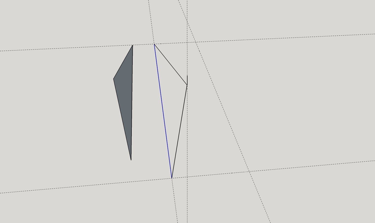
I have a little question regarding the simple drawing of a triangle by means of three touching lines, to draw an elementary pyramid
Le dessin ‘Pyramide 1’ en annexe montre :
⦁ À gauche le dessin d’un triangle quelconque dans les trois dimensions. Lorsque la dernière ligne rejoignit le début de la première, SketchUp en a conclu qu’il s’agissait d’une surface et a dessiné celle-ci en sombre automatiquement.
⦁ À droite, on distingue
…⦁ les quatre lignes en pointillé d’un rectangle horizontal (de base d’une pyramide)
…⦁ un petit tiret vertical ne servant qu’à indiquer le sommet de la pyramide, soit des quatre triangles à dessiner. L’extrémité du tiret n’est pas dans le même plan que le rectangle de base.
…⦁ Un premier triangle des arêtes d’une face de la pyramide. L’extrémité du tiret n’étant pas dans le même plan que le rectangle de base, chaque triangle est oblique par rapport au rectangle horizontal de base.
Problème : Bien que les trois arêtes du premier triangle oblique sont bien fermées, SketchUp refuse de reconnaître la surface. Pourquoi ?
Impossible to tell from the image, my guess is if you change your view you will see the edges do not meet.
Attach the model so we can see what you have.
I agree entirely with @Box : images are subject to optical illusions that can make lines appear to intersect or cross when in fact they don’t. Please attach the model.
Dear Box and Slbaumgartner,
Thanks for your quick answer.
But of course, I thought to the point that the stopping point of the 3rd line could not have touched the starting starting point ot the 1st line. I zoomed, orbit-rotated, a s o, but it seemed to be OK.
Please, find my model here attached : EnregistrementAuto_EnregistrementAuto_LEDs waterkoel lichtkap 72-18 Aquar.skp (763.4 KB)
My oblique triangle is in ‘Layer 0’.
Subsidiairy question : Am I right when I think that it is not possible to send only a few selected layers of a model ?
Please do not hesitate to tell me if I’m operating some SketchUp features faulty.
Thanks & Rgds
The edges displayed in your model when it opens do not close a coplanar loop. It also appears that you’ve got some edges that run beyonf vertices which can hinder face creation. When I copy the two long edges up away from the rest of the model it is possible to create the face by closing the loop because I don’t have any other geometry attached…
I also notice you are using layers incorrectly (now called tags). I’ve fixed that here.
All edges and faces should have Layer0/Untagged assigned to them. Only groups and components should be given layers/tags. Keep in mind that layers do not provide separation between edges and faces. You have a lot of ungrouped geometry in your model that probably ought to be grouped.
I agree that these are the main causes of the issues. Edges using non-visible tags are interfering with what he is trying to do to edges using the visible tag.
Dear DaveR and slbaumgartner,
Layers(Tags), components, groups, …
It seems that I made typically incorrect operations of beginners, and that rectifying them all, now, will consist in a tremendous task. It seems that I did not spend enough time with the right tutorial. What do you advise me ?
Take up again from the beginning ?
Is it possible to select all the lines, groups and components in each of my "layers’, one by one, make correct group and components and then assign these groups and components to new layers=tags ?
Do you know a good chapter of a good tutorial explaining the correct use of layers=tags, groups and components ?
Is it thinkable to use a tool (xml ?) that lists the sequence of all the drawned lines (with their coordinates, surfaces, components, …) in which I could manually correct the mistakes ?
If you rightclick on loose or raw geometry, you can choose Select > All on the same tag
Then, change the tag in the entity panel to ‘untagged’
Then isolate that geometry with another rightclick > Make group (or component)
Repeat for other tags, add/subtract faces if necessary with Shift
Thanks for your answers.
Indeed, it was difficult to see, but one of the four guide lines (of the rectangle) was not exactly in the same plan as the three previous ones. I can understand why. In fact, at two cross points of guide lines, I received “On the line”, but not “Intersection”.
So, I erased a good part of my drawing, rectify the erroneous guide line and recommence this part of the drawing.
I made it sure that the two rectangles and the two curved lives pertain to the same (green) plan. I expected that when my second curved line touched the big rectangle, SketchUp would recognize that it was going on a curved surface. But here too, no filling paint appears, neither when I erase the straight lines that are indide of the assembly …
Thanks for your ideas.
Each side of the rectangle is made of 6 guide lines.
Each corner must receive this strange ‘h-scape’ at the corner. The initial one is the one at back, left-side.
It is not recognized as a surface, = my issue.
Subsequently, I cannot operate a ‘push/pull’ on it.
To copy this ‘h-surface’ to another corner and also to made it spin 90°, I had like to be able to hold the precise most right point at the base of it …
and make a precise translation along the inner of the 6 guide lines, until the next corner (= the red of green line)
and make it turn 90° around this most right point.
But I need first to get a surface from this ‘h-scape’, and then the most right point at the basis.
Good grief ! I tried to access ‘Profile’ (for the correction to Sketchup Make 2017), but did not find the way, neither the 'Sketchup 8). Grrrrrr
I moved those two corners in the green direction to align with the rest of them and then the face can be filled.
One of the problems for you is that you have Display Precision set too coarsely. If you increase the Display Precision you’ll be able to see when things are out of alignment.
Thank you. My problem has been not clicking on my components first to get ‘inside’ them. Coordinates pop up automatically on loose geometry, but since I avoid loose geometry I never figured this out.
Dear Dave,
Thanks for your answer of two days ago.
I feel disappointed becasue it means that each time that there is a problem to recognize automatically that a loop is closing and so is able to make up a surface, the user will have to look at the coordinates of all its angle points, and especially the decimals.
In my example, the rectangle is made of four bundles of five guidelines, guaranteed in a same plan. Each of these guidelines were drawn guided by the red an green guidelines.
How can we make it more sure that drawing a composite perpendicular surface by means of line segments that follow the red, green or blue giudelines, or one of the guidelines of the rectangle, will be correct ?
I still wonder how a decimal error such as the one you founded, can come from. Tell me frankly if I’m one of the rare bird bumping into this issue.
Does it mean that when a loop of line segments does not make SketchUp to recognize that it is going on a surface, the user will have to validate the coordinate of each angle point of the surface, one by one ? Probably not, or else SketchUp had provided for a long time a tool (button) to help the drawer …
to make these coordinates appear,
to indicate the angle points that have the x, y or z coordinate(s) to be aligned on the other ones, until the composite surface can be recognized and painted as such.
Without wanting you to loose your precious time …
Many thanks.
Not meaning to offend, but nearly all problems with off-plane geometry are due to user error. That is, you unknowingly did something that actually told SketchUp to put that point off-plane.
Most often this comes from lack of experience with modeling in 3D via a 2D screen. SketchUp always has to analyze what you are doing to decide how far away each point was meant to be; it does not have a “working plane” that things automatically land on. Instead it relies constantly on its inference engine to guess. But if you drift off an inference snap and then click, SketchUp loses its reference and things may go astray.
As mentioned by @slbaumgartner SketchUp does not automatically have a “working plane.” But it is simple and fast enough to create one yourself. Create a temporarily-larger-than-necessary working surface such as a rectangle or a polygon (e.g., the default regular hexagon). Carefully place the working surface where you want it. Then you can either:
continue drawing your actual outline right on the working surface, and delete the outer-most edges when done (or when far enough along), or
Form a group with the working surface, draw on top of the grouped surface (but not within the group’s editing context), and delete the group when done.
In either case, SketchUp’s inference engine will easily ensure that items added to the outline (edge end-points, arc centers, guide lines etc.) fall on the plane. The result should be a face (in SketchUp terms) that fills the area within the outline that has been drawn on the working surface.
That would be one way of determine what is “wrong” with the geometry. But with techniques such as described above, it should be a rare occasion that SketchUp fails to recognize the boundary of a potential planar face. The only times that I tend to experience this issue is when merging geometry together such as exploding a sub-group or sub-component within the context of its parent group or component. If some of the newly-exploded edges fall on a plane of the context and enclose new areas, SketchUp usually detects this and treats the various resulting areas as separate faces. But if the edges are truly co-planar and yet SketchUp fails to create the expected discrete faces, then re-tracing an edge with the Line tool will usually trigger SketchUp into recognizing the expected faces.
Bonjour,
Normalement un triangle no pose pas de problème pour créer une surface.
Avant de rentrer dans plus de détail, quelques vérification basiques même si vous avez dû probablement les faire, c’est parfois sur des choses basiques qu’on bloque tous à un moment donné:
Les surfaces créées ont deux faces L’une grise l’autre blanche. avez vous regardé le résultat sous plusiers angles pour vous assurer que le blanc entre les segments de droite est en fait la face blanche?
Avez-vous essayé de cliquer au milieux des segments?
Si ces vérifications sont faites alors il y a un décalage d’au moins un point de fermeture de la forme. Ceci peut être dû à des traits de construction créés après le tracé des 2 premiers segments. Il y a quelquechose qui fait s’aimanter le dernier point. C’est fréquent dans des modèles complexes où le logiciel a de multiples points potentiels et particulièrement quand ces possibilités sont proches.