gkernan
Couple of Q’s
Is the GKWareSimpleDXF extension limited in any way the trial version? (please see .skp w/import of GKW exported part) GkWare_Expt_Test_07_21_2018.skp (167.0 KB)
And, I cannot tell for certain, but it appears it will export the “selection” only if other geometry is present in the SU model. (this is fine & preferred at least by me)
Charlie
The trial is not limited.
Looking into your model it looks like all of the arcs have been exploded.
The intention of the plugin is to preserve arcs.
Charlie - You made 2 groups - you needed to make 8. That is why you only processed 1 cutout.
More importantly the outside shape only processed partly because the plane did not have a normal of 1 or -1 (meaning the plane wasn`t precisely horizontal)
So I redid the geometry and made sure that all arc information was preserved. The test was running Find Center and Sketchup placed a construction point at the center of each arc.
I then created a group for each cutout and also for the main shape. I filled each cutout with a face so I could control the direction of the machining.
Oh my…you have been busy…thanks a million for looking at this.
I did try several different ways prior to posting, although I doubt I would ave caught the plane error.
Anyhow, good to know I would need seperate groups for each “slot”.
Thanks again,
Charlie
(Back to play w/extension some more)
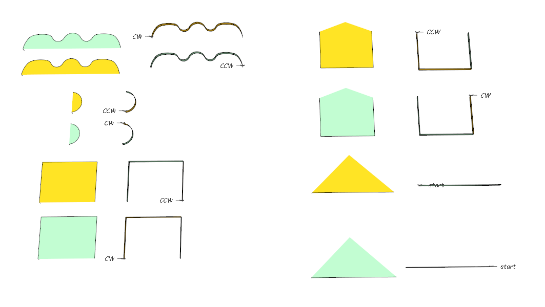
Ian had been asking about controlling polyline direction.
Notice that I have hidden 1 or more contiguous edges in these examples. Even thought these are open polylines you control direction with the face. Yellow is normal - Green is reversed face. This strategy allows you to control the direction of a straight line.
The example of the (almost a home plate) shows you that even if you can’t run a straight line between the start and end - you can have multiple hidden lines. Hidden lines are simply ignored when writing the DXF
This extension definitely does the intended job preserving the true arcs and is looking good so far through tests. I look forward to more hints and tips as they come along, especially layers as I don’t understand that part of the process or the significance.
I get that part now, it’s a very neat way to get the direction through face orientation. However, I’m still unable to get the machine to accept the DXF directly. I’m not sure if it’s the format (discussed already), or the fact the machine will not accept polylines in my case, or maybe even if it has to do with the grouping of the geometry.
I’m going to try to figure out why that’s happening still. The workaround is still exploding in Draftsight and saving as R12/14 ascii. Yes the direction isn’t there anymore but that’s set in the machine dxf import environment as well as joining selective geometries together into paths. I have the feeling I use a very odd system to the rest of the world that’s really picky, but simply getting the arcs out of SU every time as I can now is a massive leap for me.
Ian - you could see if any of the other CAM software support your CNC. You would have to which CAM software has PRE and POST for your CNC.
Layers are used by CAM software to pick out the tool for CNC machines that have tool changers. Essentially the CAM software use layer name to determine which Script is run. Scripts control many facets of the machining operation including RPM, Depth of cut, how the cutter enters into the material etc.
If you have a manual for your CAM it should specify the requirements.
Ian - The SCM Zilog 3 came out in 1999 and the SCM Zilog Plus came out in 2000. It appears that they are using the WoodWOP software (very crude). I have a client in Denmark who ran a Homag pod style CNC router with tool changer. He imports my DXF’s without any trouble. He wanted to do horizontal drilling but it turns out that WoodWOP has basterdized block inserts in a proprietary way. Suffice it to say - he has since stopped using the Homag and is now using cabmaker and its nesting capabilities.
Thanks for the info Garry. When I did the course for the software around 11 years ago the emphasis was on manually programming parts, cupboards doors etc. It is very user friendly and easy to program once you get the hang of things. It were simply mentioned that you could import DXF files, maybe there were a good reason they didn’t go into detail. The manual is very vague on DXF imports and doesn’t mention layers either.
Even now for many parts I can whip up a program faster than any CAD/CAM stuff. I assign all the toolchanges, faces, paths and depths manually. But as I’ve got more complicated the DXF is a godsend. Then I hit this wall outlined in this thread, two problems really, one of which you’ve just solved with the importer.
The other, having 4 machines that constantly run, using the same software that have hundreds of programs in “xilog” format that are outdated and need replacing. Being the only guy at the place who really understands this and has to be seen to sort this out is a headache to say the least especially as it will require further training I would think. Persuading investment in something that seems to others to work fine is another thing altogether, but if we are to progress I imagine something will have to be done.
With Sketchup and Cabmaker many of my clients can design a kitchen in 5 to 10 minutes. Transferring the information over to cutmaster takes 1 second. Optimizing all the panels in a nested configuration takes a couple of seconds. CutMaster can then create all the dxf’s for the entire kitchen in about 1 second.
Next is turning the DXF’s into G Code with the proper (modern) CAM software.
It is possible that I could provide an option that separates polylines and arcs while maintaining directionality. You could test that out by creating 2 groups - 1 as an arc - and 1 as a line. Just make sure that they share a common end / start point. Also make sure that they are ordered correctly. This test may help you determine if separating the machining operations helps or not.
You can also see if you can import a simple rectangle. If you can then your software can handle very simple DXF’s
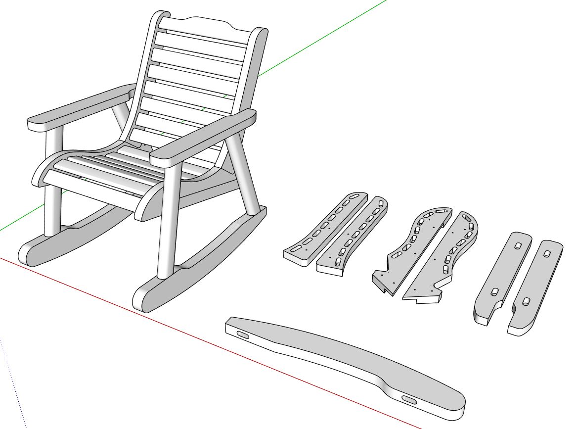
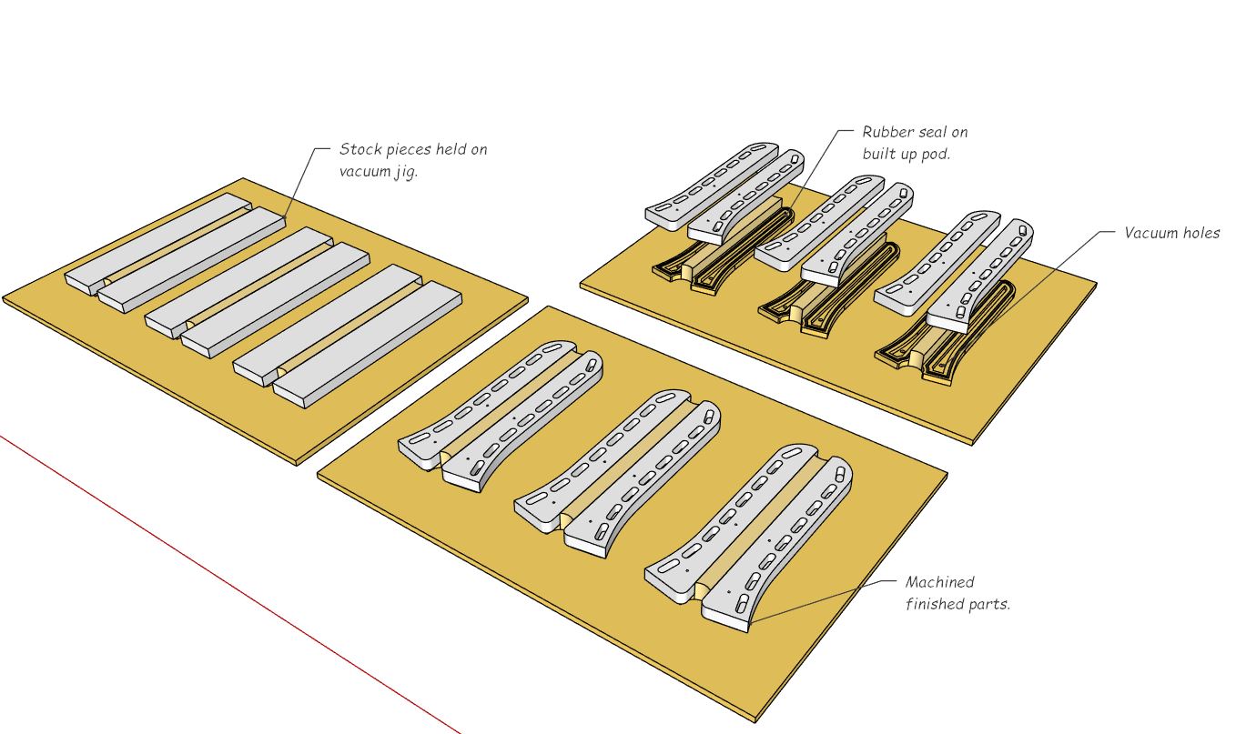
To give you an idea of what I do here’s an example of an old discontinued line that would be a good example of some of the operations I deal with. The stock pieces are cut from packs of planed dimensioned timbers. I’ve put the CNC components to one side.
I take the components and build a jig to machine them in numbers. This component I would have 6 on the left table of the machine and six on the right table (two jigs). The jig has to be designed and built too, which has vacuum pulling through holes underneath, sealed off by a rubber seal on the built up pods. The pods are built up to allow a profiling finish tool to pass around which finish planes and puts a round back on the edges after a roughing cut operation.
I think I might have narrowed the issue down to two things. If I import any of your output directly the software freezes. I don’t know if its any connection but I get the same freeze if I try to import any “BINARY” DXF that I create in Draftsight vanilla.
If I convert your output to “ASCII” DXF everything imports. However, the polylines that are created from the ARCS don’t import as such but only as straight lines. If I explode your output, only then do the arcs actually retain the “arc” they were exported with.
Did you try a single rectangle? My files are actually already “ASCII” DXF.
I bet the issue is that your old version of WoodWOP probably doesn’t support a bulge - but wants a pure arc. Unfortunately you can’t mix true arcs and lines together within a polyline.
The advantage of including all arcs and line segments together is it is much simpler for the controler - but only if your CAM supports it.
I tried one without grouping and that doesn’t seem to export at all, because there is no group, I made a Rectangle a group and that froze on straight machine import as before.
If I open the grouped rectangle export in Draftsight and save as ASCII R14/R12/2000 without exploding the polylines it goes in fine. That’s what made me think it were maybe BINARY format, but that’s not the case then.
Thanks for your help with this, I will try a few more things tomorrow but it does seem as though I may be limited by my tools. On the plus side I can get true arcs, I just have to manipulate the output a little for my strange case still.
gkernan,
I ran a couple of tests after your advice to group all, and have had some success! (thank you!)
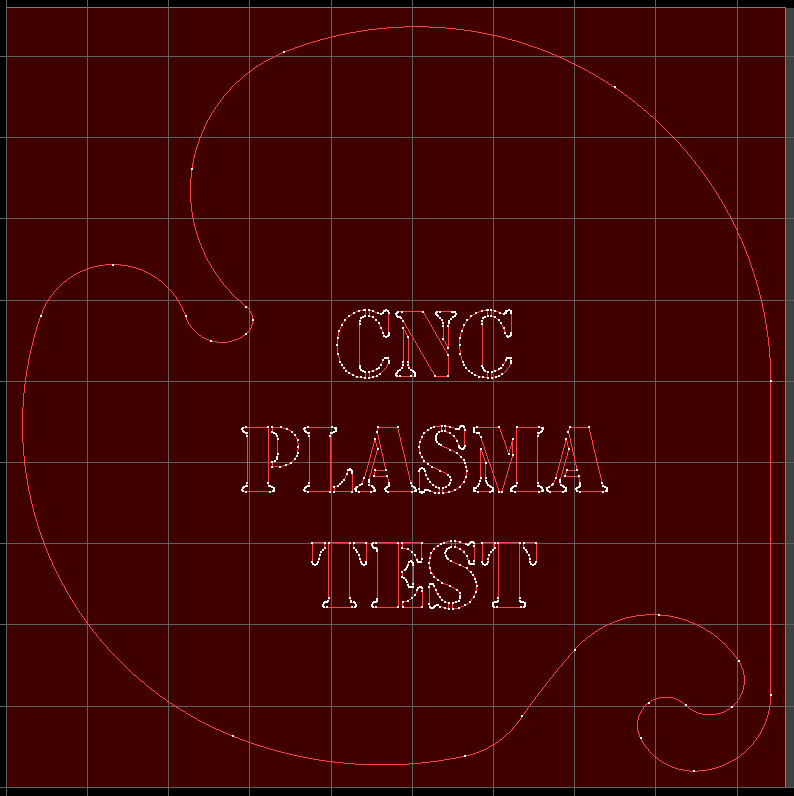
The arcs are preserved w/import to Sheetcam TNG (please see pic) Note: Text from Sketchup is another matter all together so try to ignore that for now.
SU Image
Is it possible to maintain a component in SU and nesting of same? (see metal plates in SU model/image)
I tried grouping the individual holes and preserving the component…but no dice.
Sorry no. That is why I call it Simple DXF. However, the process I used was quite simple.
Create a component where the outermost container (the component) holds a component for each machining operation. Create your true shape cutting plan by copying / rotating your parts. Select all the outermost components - explode and then put into a group. Done.
I could put a video together to show you exactly what I mean.