Thanks for the info on not using empty spaces. I did not know that since i am new to CAM.
Nonetheless, if you decide to make your extension available then you can always come back to this thread and post your decision. You have 3 months before the thread closes.
Following this thread closely & also interested in cnc plug in developement as I am considering the purchase of a cnc plasma table.
While quite proficient w/SU, I am aware of the limitations illustrated in this thread.
Having a plug in specifically tailored for cnc would eliminate the need for me to purchase additional software to play nice with the CAM. ($ for your plug-in)
Charlie
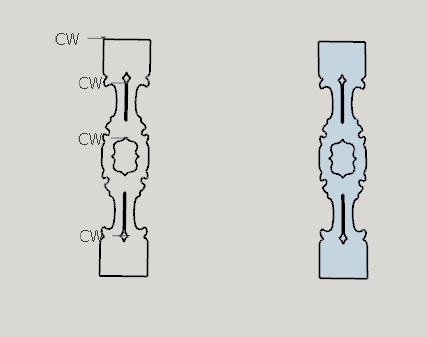
To make this work I grabbed 1/4 quadrant of the shape, copied it and stretched it diagonally to 10 times it’s size. Then I put the geometry into a group. Next I traced it and used the 3 point arc tool to turn the curves into true arcs. Then I copied and mirrored to the other 3 quadrants. Finally I stretched the shape back to it’s original size. I grouped the polylines into 4 machining operations.<a class=“attachment”
Thanks for taking the time to look at this. I’ll have to digest this a bit more but it sounds like I have some learning to do before using any potential plugin you may develop.
The thrust I reckon is to use lines and arcs, with no curves.?. I had forgotten exactly how I drew the thing.
I’ll send the dxf to the plasmacam man and hopefully I won’t have worn out my welcome with him.
It is always best if you can use arcs and circles as opposed to many line segments. Some CNC machines do not like very very tiny segments. In sketchup small line segments may end up as duplicate points.
As I tend to lie in bed at night thinking about things like this issue, I’ve been compelled to try to understand what it is that flips the arcs on the x axis in the machine software. I usually just mess around until it fixes itself as I’m just trying to get something done at the time. Over the last few days in my bits of spare time I’ve been pumping out test after test trying to spot where it goes wrong, jumping backwards and forwards between 3 programs takes a lot of patience! I think I have eventually found a pattern that is consistent with every export.
The rules:
Circles always work.
Arcs must be drawn “anti-clockwise.”
“flip along” and “copy rotate” break a good arc.
Any singular arc offset works, including from “flip along” or “copy rotate” arcs.
So I then made a prediction test with my rules in mind to see if I could make and break what I wanted. I added the rules and some other information…
I have found that all this is like treading on eggshells to get something that works. Essentially by using SketchUp’s “flip along” and “copy rotate” to efficiently model, you are only creating problems for the export down the line. Let a lone remembering to draw every arc anti-clockwise, it’s pretty ridiculous.
I have said before I only require lines and arcs exports, but many others require polylines which I have been unable to produce natively. I have been able to produce polylines from my good exports in DraftSight, but as Box put it so well, its jumping through hoops.
I thought I’d share my findings with everyone just to make it even clearer how difficult it can be to get something that is even close to usable natively from SU. I believe I have found the pattern, and in finding it has only justified my thoughts even more as how much use an extension for this could be.
I just redid the rounded square with only counter clockwise arcs and indeed it works in my machine software.
I also ran the rounded square through Autocad and i was able to use the polyline function to combine the 4 edges and 4 arcs into a single polyline.
My conclusions are that this issue is clearly a bug in the exporter and not just a lack of support for CAM as initially stated by gkernan.
Hopefully the Sketchup team will see this thread and have an interest in fixing the problem.
Of course, even if they did fix the export problem, the lack of polyline function while retaining true arcs still means the user needs to go through another program to create polylines - and that means more time and more money wasted. For this reason i fully agree that gkernans plugin would still be useful.
Sketchup’s DXF exporter honors arc direction as I would expect it to. So I wouldn’t call this a bug.
There are times when CNC requires CW rotation and other times when CNC requires CCW rotation. For example we want the router to rout the outside of the part and perhaps to rout a cutout. In these cases you need opposite rotations.
There are situations where the pattern is quite complex and you really need to mirror quadrants. The solution is to use the outer loop of the face and honor the normal of the face to determine direction.
Having said that - there are improvements that could happen with Sketchup’s DXF import. My import brought in a polyline bulge as an arc whereas Sketchup’s import brought it in as many small line segments.
I am considering adding a user interface for a standalone dxf import where you can turn on / off several features. This is based on my experience with different requirements of different CAM.
2D or 3D
Show construction points and direction symbols
Split polyline at arcs
Holes need extrusions
Output metric or imperial
significant number of decimals.
In Autocad, i draw a horizontal line and a vertical line that are disconnected. I then connect them with a CCW arc. I open up the file in the machine software and its proper. I then redraw the same horizontal and vertical line and connect them with a CW arc. I open up that file in the machine software and its proper.
Therefore i conclude that the Autocad exporter has no anomalies.
In Sketchup, i draw a horizontal line and a vertical line that are disconnected. I then connect them with a CCW arc. I open up the file in the machine software and its proper. I then redraw the same horizontal and vertical line and connect them with a CW arc. I open up that file in the machine software and the arc is dislodged.
Therefore i conclude that the Sketchup exporter has an anomaly.
Can you please explain to me how i could be incorrect about this basic deduction?
I am in the process of creating a new plugin which will go in the folder GKWare_Simple_DXF. These buttons represent DXF import and DXF export.
It will have a small configuration dialog box which allows you to set whether you want 2D or 3D and if your CAM software supports Blocks or not and also whether circles require extrusions or not.
There will be a pdf file manual.
I may provide some examples.
The only DXF’s that you will be able to import are the ones that this DXF export creates. You may import many DXF’s into a single sketchup model.
Each imported DXF will have an attribute containing the full path of the DXF. When you go to save your changes you will see the same name but with an added underscore before the .dxf. If you remove the added underscore then you will over write the original file that you imported.
If you create a DXF from scratch then you can call it whatever you want and place it wherever you want. You are not required to provide the file extension. The plugin will add one when necessary
Geometry that is placed within a group will NOT be put into an DXF block.
Comments and or suggestions at this time are welcomed.
Unfortunately i have been struck with a serious physical health issue that needs to treated. Therefore i cannot participate in this thread until i get well.
My apologies for showing great interest and then pulling out. Hopefully the other users who showed interest in this thread will hop along and give you suggestions.
@gkernan I’m glad to hear that you are still working on this. You’ve already proven that your method/programming works. I don’t understand the whole of how to use it just yet but I think you seem to have the options covered for different machine requirements given your knowledge of the field. I suppose that would be down to testing though.
Something I wonder is what format the DXF export will be? I think I mentioned previously that the only format that is accepted properly in my case is either “ASCII R12” or “ASCII R14”. That’s the main reason I have to put the export into Draftsight to save it as one if those formats before the machine.
I think they are very old formats and the machine software I use may be to blame for that. However, it seems a big job to get new software for 4 machining centres for the sake of a file format when it’s done so well for probably 11 years or so. “If it ain’t broke don’t fix it”.
I thought I’d mention that again in case there were anything you could do in that way to save the extra step. I’ll leave that with you for now, I look forward to further progress.
Ian - I use bare bones dxf primitives. That is why the files are so small. This happens to be acceptable by all the CAM software that I have worked with.
I don’t worry about version numbers as almost all CAD packages can handle the DXF’s that I create.
What CAM software are you using? Maybe you told me before - but I don’t remember.
I told a lie, well forgot really because earlier in the thread, when you sent me the examples I wrote:
That were with “3D first” example. I just tried again for kicks with “2d first” and that one froze it up too. Maybe it is the way the DXF is created with the blocks for example (if you did it that way). All I can really say to you, is that again all the geometry is of a single flat plane and exploded into separate entities and that seems to work.
Seen as though I don’t know what options you used and to avoid confusion I will give you the original SKP again if you care to try a few options with it. I don’t expect blood but it would be awesome to to get rid of the “middle man”. Gkernan.skp (101.0 KB)
Layers are very important. The only thing is if you have a layer name with spaces then I will replace the space with an underscore. Most CAM software cannot handle spaces in a layer name.