So I’m often needing to resize and rotate, say, a timber cross section symbol - a rectangle with diagonals…
I group these (for integrity) and then to edit I’d open the group and then resize the rectangle and then have to edit the diagonals to the new rectangle vertices.
And as a group the rotation becomes problematic trying to align the entire group with other line elements.
So I created this ungrouped timber symbol turning the diagonals into leaders…
Interesting approach. I presume this would become a scrapbook object?
Any reason not to use a scaled drawing? You could rotate it as needed, adjust the scale to suit the scale of the viewport it lays over and resize it to fit different sized timbers.
You could also make a set of scaled drawing symbols for the standard timber dimensions. Then you’d only need to adjust their scale to suit the application.
With the current project (a loft conversion) it’s not so much about resizability - it’s that when rotated a rectangle’s gizmo retains alignment with the rectangle axes and so aligning with angled drawing elements is straightforward - I tend to reuse linework groups that I have on the page, so if I need another timber symbol I just grab it from elsewhere on the page… and if it’s grouped then the gizmo doesn’t align with the rectangle axes but with the group axes.
So lazily grabbing an already rotated group from the page causes tedious editing.
But if I’m grabbing a scaled timber symbol from the scrapbook every time like you suggest Dave, then there is no issue with rotation.
Some scrapbook organisation to consider is in order perhaps…
Not making any claims to a productivity hack or whether it’s practical - I just find it interesting.
I haven’t implemented this yet because I currently have the rounded box with a light grey fill and I don’t think that can be hacked.
I found myself grouping the text box and the rounded box together for easy manoeuvrability but then if I copied the group to elsewhere on the drawing and wanted to edit the text I’d have to enter the group and then enter the text box.
With this hack you just need to enter text box.
Of course I could have a template where I have these pre-made and pre-numbered off the paper area and just drag and drop them into the drawing.
The fill will export to PDF but destroys the ability to bodily move - the third point stays anchored to the page with the two end points moving with the text box.
Whether it can be easily done or not via some other workflow aside…
I’ve tended towards drawing directly in Layout for many of my large scale detailed drawings tracing over a simple SketchUp model scene.
So I began to create Layout ‘components’ that I could reuse.
In this case I created a window / wall abutment object but I would have to manually draw in the rest of the window in-between or enter the object to edit the geometry.
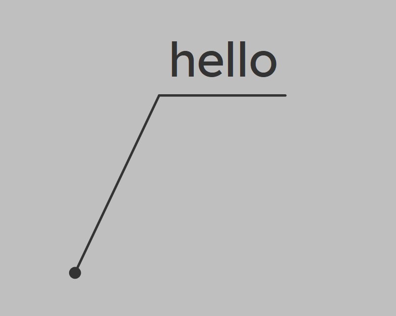
So I wondered if I could leverage the properties of leaders.
This might explain better what’s going on:
The rectangle on the right is really a 3 segment line that has a start and end ‘arrow’ style.
I would suggest you set your “shortcuts & tricks” aside and review the basics of Sketchup and Layout. You are way out there somewhere and you “tricks” are causing you to do a lot of unnecessary editing. Drawing 2D details in Layout is a tipoff that your workflow is strange.
You seem to be very confused as to what Sketchup can do for you. Take time to learn the basics is very important for sucess.
A weakness that I have is that I can spend an inordinate amount of time on my condocs - they have to look super good (in my eyes) depending on what whim in aesthetic I might have at the time.
In the case of the label above, as I mentioned, I like the style but because you can’t make that style of label in Layout I haven’t bothered myself about it until this evening on a whim - it took me all of a few minutes to conjure up.
Actually I don’t think it will be as cumbersome as one might think in actual condoc production not least because with the native label you have to select the right part of the leader to move the label bodily.
In the case of the window detail further up - again it’s down to my obsessiveness with how things look.
Whilst in SketchUp, for my dynamic window components, I have a generic simple 2D window symbol group for drawings down to 1:50, for my 1:25, 1:10, 1:5 drawings, this simple window symbol is not acceptable for me and I prefer a more detailed representation.
It didn’t take too long to work out my Layout window “component” - it’s certainly saving me a lot of time.
I find all these experiments interesting. I would like ways to have better leaders and symbols around text tags (different shapes for text bounding boxes).
However, I don’t understand why would you draw details on Layout. I do the same work you do, but on section faces, on top of the model, in SketchUp with the added advantages that:
It’s easier to draw;
It’s easier to texture and hatch;
You can adjust model to fit details afterwards, easily, if needed;
You can use components;
You draw on 1:1 scale;
and finally, you can avoid Layout incumbrances, worse inference system, worse tools and slowness.
I actually use this exact type of note for elevation markers to denote finish grade, top of wall etc. I just have it as a scrapbook item where I edit the text and position the leader. Having it be an active leader type makes sense to me.