Just to clarify my comment above (and at the risk of the thread going off topic )…
The inordinate amount of time I spend on my condocs is not because of Layout, on the contrary Layout works very well for me, but not to say it doesn’t need improving.
It’s because of my particular obsession for how I present my documents.
My SU models only have sufficient detail for down to 1:50 general overviews using native section fills and simple 2D SU objects.
1:20 and below I have re-usable Layout scaled “components” and detail views.
I’m always in awe with how you guys manage detail libraries. I can’t replicate 95% of my details from one project to the other… I always deal with different construction methodologies, contexts and shapes both in refurbishments as well as new construction. It surely makes sense to replicate if possible.
My models also go up to 1:50 scale, but from then on, we do draw up every detail, custom made for each project, up to 1:5 or even 1:1 scale. We have found the best way to do that is in Section Cut Faces or simple 2D sketchup drawings, that we then annotate and dimension in Layout.
It relies on the fact that once an element has had an ‘arrow’ style applied to it, the start and end points of the line or multi-segment line will stick to another element/object.
It would seem that it requires either a start or end point and not both.
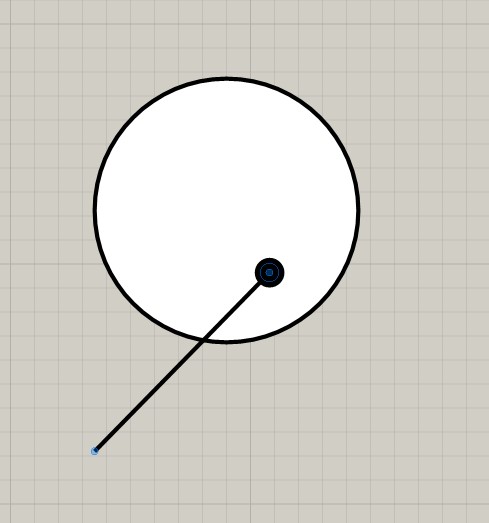
In the example below I have applied the dot arrow style to one end of the line:
I double click the line to edit it and move one point to anywhere on the perimeter or within the circle.
In this case the dot but it could have been the plain end as well:
In the case of the custom label above I gave the line segment a shorten arrow style and moved the start and end point to the bottom vertices of the text box.
It should be noted that if the line segment had a third node the behaviour would be different:
When I started with LO I did some annotations that looked like the ones shown at the beginning of this post, and did a lot of double clicking to edit them. I was trying to recreate a graphic style that I used on my previous CAD software. They did look good, but in the end, I started using more and more simple layout tools, like simple rectangular leader outlines and fills, playing with alignment and other native tools. This lead me to a slightly different aesthetic for my drawings, but way faster productivity. No more double clicking into nested groups to edit simple text and things like that.
That´s not to say that Layout could receive a lot of improvements in this (and other) area, but in order to make things flow faster, I ended up adapting native items.
I do like some of those experiments though (leaders for x´s)
One example is in elevations, instead of adding graphic triangles up or down to note elevations, I use ▲▼↓↑▼◄◊ ▻◁∆ or similar, from character map, so a elevation for under slab dimension would be
▲ n+: 2,560 or similar, and the text could even be replaced by an autotext z coordinate. This could be a leader that is copied over several times. and relocated.
I’m seeing a thousand ways this can work to improve my workflow, particularly with numbering as you mentioned earlier, I’m currently making a group (object & number) and need multiple clicks to edit. I’m into it! But, I may come back with questions!