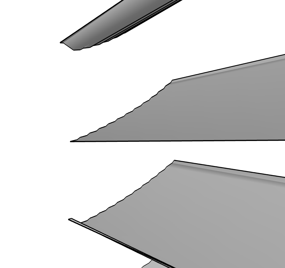
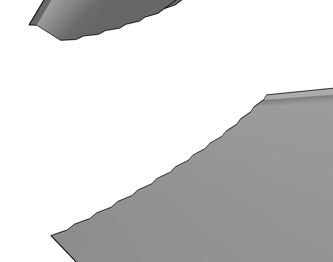
Hi all, I’m having trouble intersecting faces, basically its a turbine blade and I’m trying to intersect it with a cylinder to cut off the blades at the exact height they should be. but its making geometry all squiggly. I presume its because I’m trying to intersect two curved faces and the intersection points are messing up. can anybody advise on an alternate method, plugin or fix? i have tried using vectored push pull from from tig but the problem is the blades need to flatten off on the end.
Hi Wo3Dan, I usually use components! i had exploded them to use the solid inspector I think I just took completely the wrong approach from the beginning. Now i’ve just created the central cylinder or ‘blade carrier’, reduced the softening and extruded the blade out, created a component and copied that round the blade carrier then adjusted the ‘twist’ of the blade at the end by 20degrees to change them all. then I’ve exploded it and scaled the circle on the back to create the conical shape on the blade carrier. - hope that mumbojumbo makes sense.
yeah I also noticed that initially I hadn’t created circles with the segments that represent the amount of blades, essentially i just used the same amount of segments on all rotors and then just divided the faces of each segment segments going backwards from the front rotor, which would, as you mentioned, mean diffirent blade sizes
Dan
If you take just one blade component and use a section plane perpendicular to its length, you’ll have a good method to “investigate” how it will intersect with a ciyindrical carrier: sort of smooth or too squiggly.