When I use Intersect Face with Model, it leaves rough edges. Any ideas on how to solve this?

When I look at your figure on the right side, I already see those roughnesses in the ends of the edges where they pierce the surface. I suspect it has to do with the shape of the fuselage you are intersecting. Perhaps the interaction between the edges that define that shape and the ones making up your new part. If you turn on view->hidden geometry, maybe you can see why.
1 Like

Need to see the “before” to show how the two sets of edges are meeting each other.
1 Like
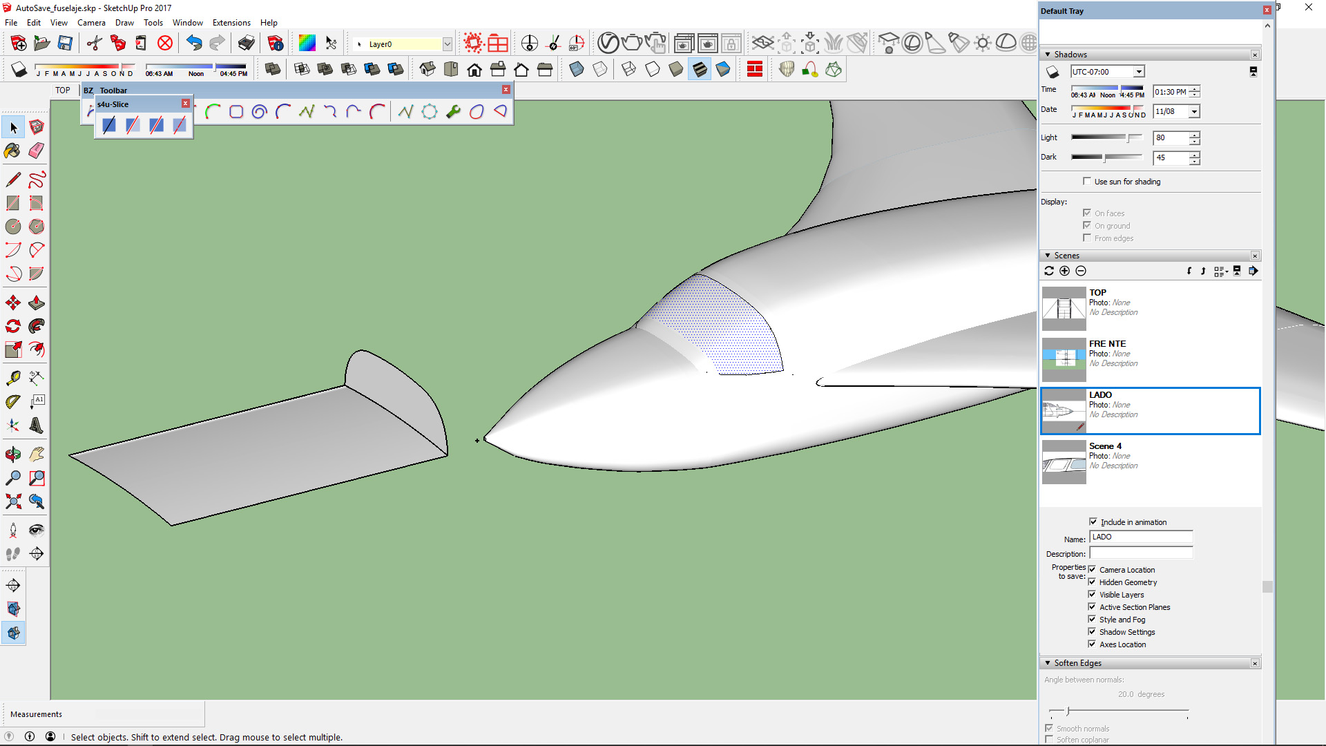
It is in fact showing the rough edge even before clicking on Intersect. I have tried using the Substract /Intersect solid tools plus a few plug ins to no avail. The intersecting solid that forms the window is made as a smooth polyline, and extruded .

What Tool did you use to create that “polyline”?
1 Like
The rough edge is the result of the face that the curved surfaces are represented by a series of flat surfaces. You can make it appear less rough by using more segments for the curves used to create the surfaces but you’ll never get a perfectly smooth curve.
1 Like
the number of intersecting points need to match to achieve a smooth result…
they are all over the place…
john
1 Like
You mean adding more subdivisions to the solid surface? The extruded window is a Bezier curve. Here it using Substract:

COuld you eleaborate? tnx
as u can see the bottom sides seem fine.
BZ_Toolbar you can see it active in the screen shot. I also tried exploding curve into segments… to no avail.
if your target has 160 intersect target points your object needs 160 intersect points that align to the target…
try it with 2 cylinders, when the geometry is aligned it looks smooth, out of alignment look staggered…
john
3 Likes
Which curve? You can change the number of segments used in the curves. Exploding curves wouldn’t help.
As John points out, you need the same number of segments or faces on the intersecting surfaces. And the edges need to be aligned.
1 Like
I tested using a cylinder with 100 sided segments ,I didnt even align to anything. As you can see the result is perfect. So I think that narrows down the problem to the intersecting solid. Now how can I add more segments to the solid that forms the window?

Here is my basic intersecting geometry to form the front window. How can I add more segments. that option is grayed out.

John was referring to a separate example to see the difference because of the alignment of segments, e.g. like this …

7 Likes
SOLVED IT!!! I narrowed down the problem to the intersecting geometry. Although complex, the fuselage was fine. Made a few tests and remodeled the intersecting geometry to this and VOILLA! IThe key is that the curbed profile is now really flat.and cuts on the Z axis rather than X. Thanks to all for the support.
This topic was automatically closed 183 days after the last reply. New replies are no longer allowed.