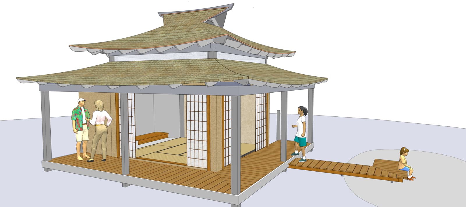
Folks, I’m going to build and ship this nice kit for one of my azumaya designs, all the main structural part anyway, except this one also has a surrounding awning type roof all 4 sides of the building, which adds a lot more posts for the footing layout! The Posts all sit on raised concrete columns (1e.png) and we need them placed accurately.
I can create my normal plans for the footing layout, with a normal square or rectangular building it’s pretty easy and easy to follow, but with the additional offset Posts it’s getting confusing!
as you see in 1d Layout.png, I can locate the exact centers of the post / footings. I’d like to give his concrete contractor some sort of accurate file, so what’s the best way to do this? Is there some sort of point cloud a surveyor can use?