From a post about “Draw a line perpendicular to a line or surface in SketchUp” (Make, Pro, Web, iPad), using native tools

From a post about “Draw a line perpendicular to a line or surface in SketchUp” (Make, Pro, Web, iPad), using native tools
I saw the video pop up in my subscriptions and knew it was about autocad being better than sketchup… ![]()
Salut Pierre,
a pleasure to read your comments on the posts.
I like AutoCAD, it was the first program I learned, so I will add tutorials for SketchUp ‘AutoCAD alike’. ![]()
I had the same thought!
From a post about ‘connecting lanscape’
Connecting three terrains into one in SketchUp and texturing them in Blender, and importing back in SketchUp as DAE file.

Hi @Royce,
if you want to learn something new, besides the native tools option and create that one-click piece movement, you can try this, with ‘geometry nodes’. I used one of your models for illustration. Once that modifier is created, you can import an .SKP model and apply that modifier to it.
Based on this tutorial.
Awesome video. ![]()
Modeling a curved & battered boulder wall (using geometry nodes)

Imported in SketchUp
Based on this tutorial.
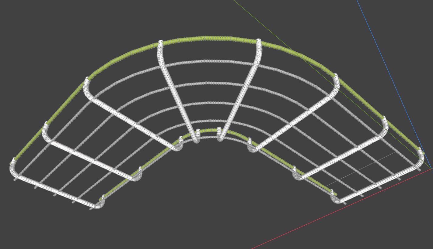
From this post about ‘Profile Builder - cable tray’
Generating a cable tray using Profile Builder extension
Hidden Geometry in SketchUp for Web (Free vs. Go licenses)
Free license
Right Tray - Display - Hidden Geometry.
Go license
Right Tray - Styles - Edit Style - Model Settings - Hidden Geometry.
")
Hi @Cotty, @ateliernab (Pierre),
without a 3D printer at hand, I will rely on your experience and help. Two questions to start with:
what is the maximum size you can print with an average printer - 22x22 cm?
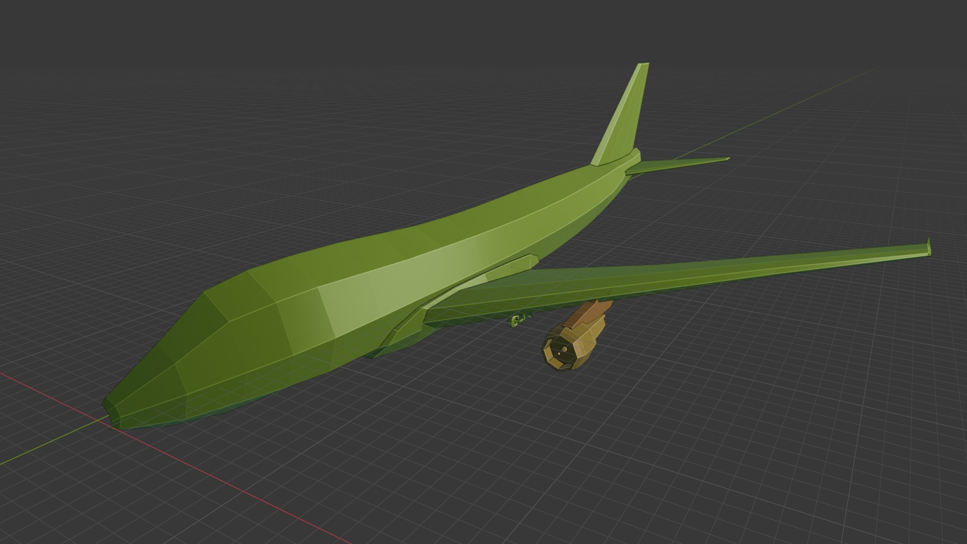
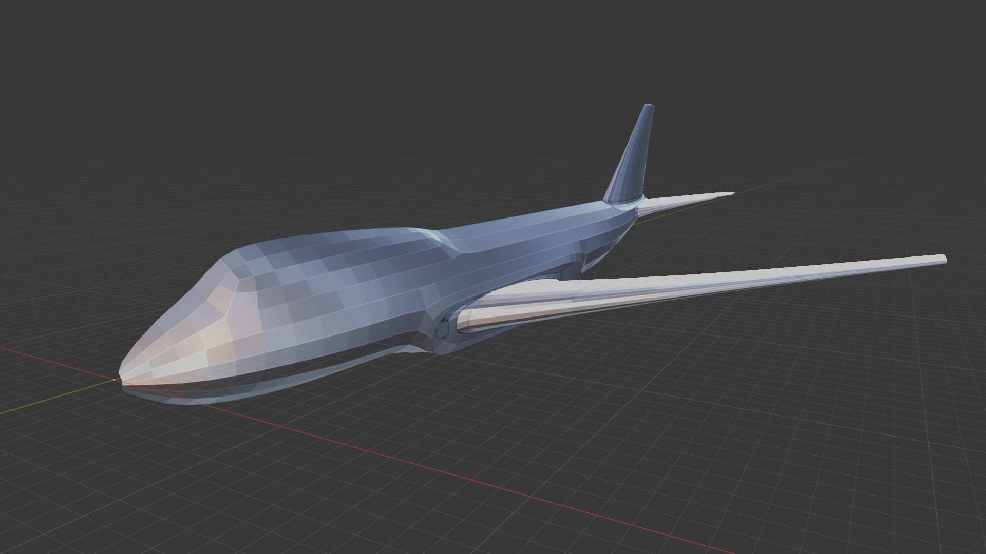
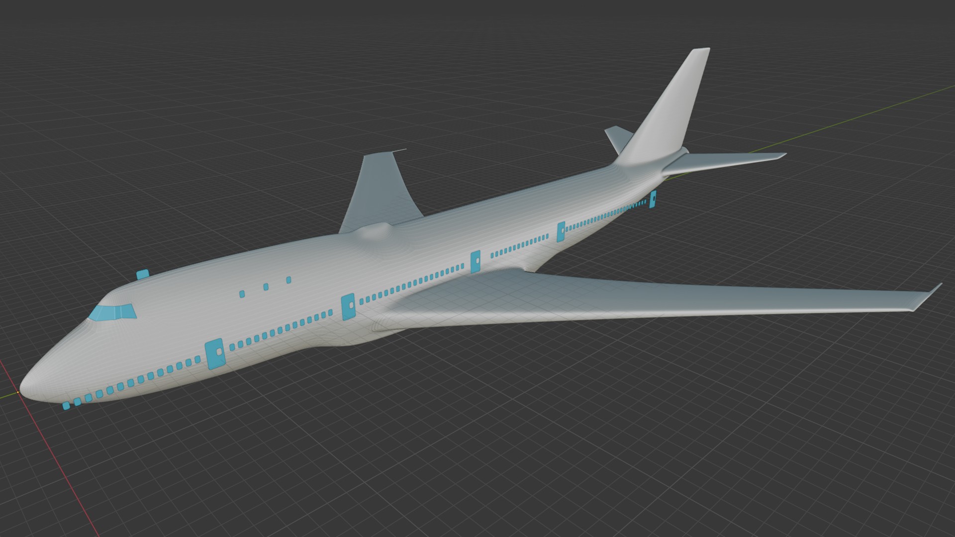
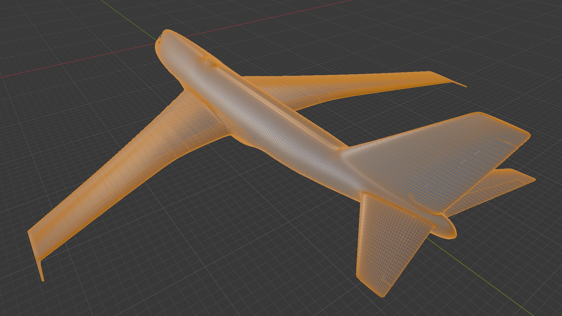
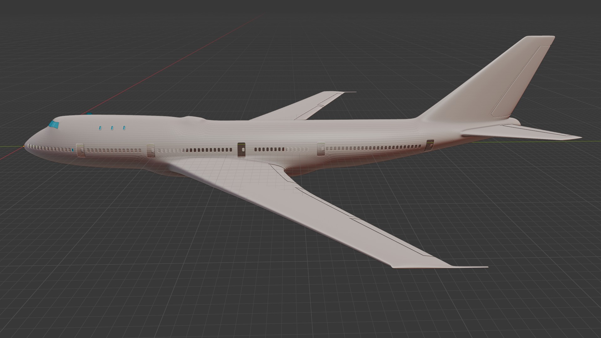
the plane I am modeling and you saw in the pictures, is 75 m long, and I am interested in knowing if the landing gear (2 m) and the windows (32 cm) are visible when printing at that small scale? Or is it necessary to remove details from the landing gear or enlarge them as much as possible?
Thank you in advance!
dimensions in photos below
if you want to print it as one piece…
the bambu P1S is 25*25cm. the mini is 18
so… about 1cm per 3m of plane. at that scale, the landing gear will be 6-7mm tall and the windows 1mm
off course, if you start cutting it in separate pieces, then you can make it bigger. the biggest I would be willing to make it would be to print the wings and tail separately, and to slice the fuselage like a long sausage. if you print the fuselage’s parts that way, you could scale it up so the fuselage’s section is about 25cm
I printed that one last spring
https://makerworld.com/en/models/79162-bambu-boeing-737?from=search#profileId-354130
The ‘standard’ nozzle diameter is 0.4 mm, which should be kept in mind when printing. Inner corners can be quite angular, but outer corners have a radius that affects the horizontal print resolution for very small geometries. Vertically, a standard FDM printer has a reasonable minimum layer height of approx. 0.1 mm, which then determines the possible resolution in the z-direction. However, with this resolution, a larger print takes a correspondingly long time; layer thicknesses of 0.2 to 0.3 mm are more common here. As Pierre already mentioned, it is always possible to divide the model into smaller parts for greater print. Most materials can be easily glued together, e.g. with superglue.
The chassis is rather difficult to print in its current form, as many parts are suspended in mid-air and will probably require support structures during printing. These can be difficult to remove in the case of very small structures. A resin printer would probably be advantageous here, as it allows smaller structural supports to be printed.
Merci Pierre ! Danke, Cotty! ![]()
I have to study what you wrote to me to understand it well and apply it to the model I am creating.
… and you should have a printer ![]()