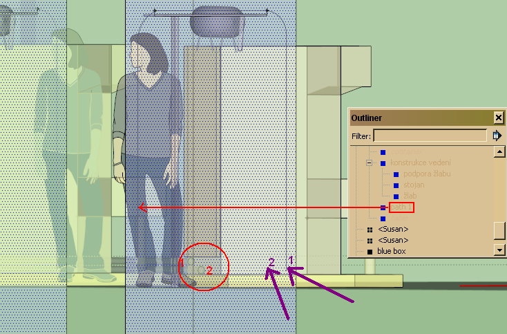
In the image I have depicted where the yellow pipes should be placed. The first pipe red number 1 starts where the red arrow is pointed and it should be finished where the violet number 1 is placed. The same thing with the second pipe. The pipes should go up to a construction to hold it.
I have added a rectangle which helped me to draw the first pipe.The rectangle is selected on the image. I have moved the first path -27mm according green axis, so now it is placed in the construction.
Now I need to draw the second pipe. When I display the model in the back view I tried to draw it to the plane. I have taken the line tool and wanted to start in the place where you see the circle of the second pipe. The problem is that the line will not start to be drawn on the face of the rectangle been selected on the image. By incident it started on the circle… this is first problem. The second problem comes when I want to click the end of the line to the position where the arc starts on the left. The arc I have already made is not on the face of the rectangle (you remember I have moved the first pipe). So the end point sticks to the path instead to the face… But I need to use the first path to follow the same arc path (in the back view).
Not sure if my message is clear… Simply I want to follow the path but on the rectangle, not on the first path or on the circle in the rear.
Oh I found it out. First I had to locate the plane (rectangle) and then hold shift. Then I moved the pointer to top of the circle to draw the start point on the plane. I have seen label “Constrained on plane from Point” which indicated that I am drawing on the rectangle because I locked it to it using shift. Similar way when I draw the arc and other lines.
Glad you found what you were looking for but, some suggestions:
1 SU primitive geometry is sticky in the sense basic geometry like lines intersect when the touch so they may move together;
2 That characteristic is avoided by making almost exclusive use of components ( most often components but groups also);
3 Layers are then used to control the visibility of groups and components. You are not doing that so the drawing gets cluttered and can confuse you.
… Make sure you read up on their use;
4 Component definitions are invariant under scaling, rotation , moving so you can use the same model for each of the weld stations unless you go internal to it for edit purposes than it needs to be unique. When you create a component there is a name box that allows you to assign a unique name for each so it make it easier for you to keep track
5 You may want to create a separate piping drawing to help out and if you looking under the model info drop down for components there is an option for the visibility of those componets as you select others tha should be useful to you also hope that helps.
Good Luck
BTW there are plugins called pipe along path and tube along path where you can draw just the path and then it will extrude pipe or tube along that path.
You can also just use the follow me tool, at the start of the path draw circle perpendicular to the path. Make it simple say like 6 sides and 25 mm dia ( at normal viewing distance tha should noy show, slect the total path, then select the area of the circle and tha will extrude along the total path length. You can select that pipe and move a copy the 27 mm you want. Alternatively position path first and then do the follow me operation. Remember the comment about the primitive geo sticking together unless it is isolated.