Trying to extrude a face with follow me along a radius. Need a perfect 60 degree section of a circle. The face in question seems to be in plane, its large and not too complex. It sits perfectly along the red axis. I select the 60 degree section of circle as path, click follow me, then select the face. The resulting form is off axis just slightly. The starting plane has shifted and the end plane has exceeded its mark. Please advise as to what I might be doing wrong. Many thanks!
60deg_followme_pathface.skp (89.2 KB)
60deg_followme_result.skp (1.3 MB)
Please make a component of the face the path and the result, save it, and attach it to the original post.
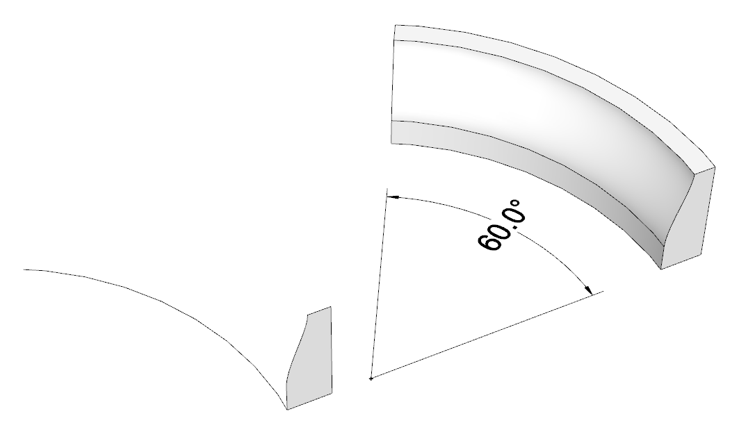
Follow me is very specific when it comes to the start and finish, it always starts and ends perpendicular to the first and last segment of your path.
In your case the 60 deg arc has angled ends and so the faces move.
Easier to cut it out of a full follow me circle.
Thanks for your reply, I have uploaded the face, path and the result.
Thank you for your reply. I think I am doing this, it seems like the steps I have taken.
Share your .skp file.
Thank you. I have tried that but when I use solid tools to slice the section out it corrupts the object after the first cut, its beyond repair andI cant get to the second cut. Must be the face profile is no good. But I cant figure out why. Also I have tried first building a 60 section with a plain rectangular profile and then using follow me to shave off the sides, but this also results in bad geometry.
60deg_followme_pathface.skp (89.2 KB)
60deg_followme_result.skp (1.3 MB)
No you didn’t
You should cut out 60 degrees starting and ending on midpoints of the first, resp. last segment.
That guarantees that your profile sits on the arc perpendicular to the first hallf segment and end the same way.
As I mentioned the first and last segments will force the path.
You can see here I made it on axis by adjusting the segments.
It’s a tiny difference but you have 120 segments in a small arc.


Here’s what happens in a somewhat larger format, by using only 12 segments for the circles you can see the error better.
Midpoints on the arc segments. Same thing I mentioend and showed in my first reply.
Thank you, is this because of number of segments i’m using? or how I end the circle operation?
Thank you so much for this. I see what you mean.
I can’t tell because of the large number of segments but see @Box’s giff to see what I meant. (second example shown)
Not because of the number of segments although the number you are using seems rather excessive. The number needs to be dividisble by 6 so there are correctly aligned segments at each end of your 60° arc. You just need to split the edge of the circle at the appropriate midpoints. I did what I showed and what Box and Wo3Dan have been showing you with your file.
60deg_followme_pathface.skp (717.5 KB)
Thank you everybody for you fast reply and patience with my idiocy. Your explanations are right on point and I understand the issue and the problem. So many thanks to Box, Dave, and Wo3Dan for helping me solve this issue so quickly.
btw, the part is for CNC carving, and then molding and concrete casting. at full scale the extruded part in question is about 7.5 feet. That is why I am using so many segments in the circle.