I’m using a component from 3D Warehouse
When I’m trying to Move it for some reason no any snapping points appear on the corners of the rectangular containing the object
The same issue when I’m trying to use Rotate tool
Whilst the Scale reveals all the corners perfectly fine.
I’ve tried various View->Edge styles and View->Face styles as advised in some posts here , but nothing helps
What can be the issue??
Was there something that makes you expect handles on the bounding box of the component when using Move or Rotate? There have never been in any version handles except with the Scale tool.
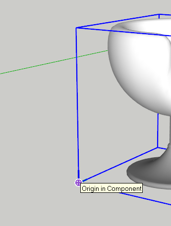
Now with SketchUp 2017 there will be an inference point at the component’s origin as shown here. And with the Move tool, red + indicating points you can grab to rotate the component about the center of the bounding box.
By the way, there’s a maintenance update for SU2017. The version number is now 17.2.xxxx Please update your profile,too. It still shows SU2015 as your current version.
Hi
Thank you for a quick reply
The issue is that the inference point are not coming up (I’m not expecting handles, that was just to illustrate that handles are there when I use the Scale tool). Out of 3 chairs I’ve tried, the first two have the same issue - I can snap to the object, but not to it’s rectangular frame surrounding it:
The third component acts as expected though - inference points are coming up
. So I guess it depends on how the component was made in first instance.
Is it possible to change some property of the component to make inference points coming up on the prev two components as well?
As I said in my post, there is a mark at the origin of the component. In your first screen shot, that mark is displayed. It’s just that the origin is not at the corner of the bounding box as it is in your second shot. You can see the component’s axes, to prove that. Evidently the author placed the origin at the edge of the base in the first one and the author of the second one didn’t bother to move it.
You can change the axes location and orientation by right clicking on the component and choose Change Axes.
I’m missing something:
What I want:
a) as the chair is round I want to be able to snap to the corners of the bounding box when I move it to make sure that the chair does not end up for example being partially in the wall, but fits neatly into the corner of the room
2) All I can snap to with the first two chairs are the points on the component, whilst the bounding box does not give any snapping points for some reason
I’ve tried now to move the axes, but
a) I can’t place the axes into the corner of the box as box doesn’t show the inference points in the corner still ( e.g I can’t snap to the corner of the box):
The edges of the bounding box are not geometry. IF the component’s origin is located at a corner of the bounding box, you get an inference point but the origin is not required to be there. The origin is the insertion point of the component. When you bring in an instance of a component from the Component’s window, you will have hold of it by its origin. If you aren’t deliberate about where you place the axes and origin, they will, be default, be located at the lower front left of the component’s bounding box. There are many cases where that isn’t the logical point to grab the component for insertion but that is up to you.
For components you get from the warehouse, you should check to see where the author left the origin. Does that make sense for how you’ll use it? If not, move it to where it should be. Frankly, with chairs like those in your screen grabs, I would place the origin at the center on the ground. But that’s just me.
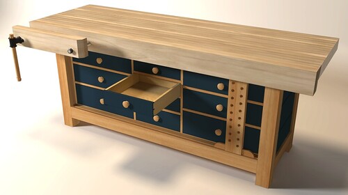
Here are a couple of examples in which I centered the origins on components to make them easier to place.
I centered the origin of the glass components on the bottom of the glass so I could quickly drop them into the holes in the tray and know they are center.
I did the same sort of thing for the knob component on this bench. Then it was dead easy to drop the knobs on the centers of the drawer front.
Thanks a lot, makes sense re the axes. Lovely drawings
But unfortunately I’m not still clear on how to move the chair without using a FredoTool? E.g to make sure that it fits perfectly into the corner of the room, i.e touches but not intersects with the walls?
Can you please explain(or let me know where to read) on how to identify the most protruding point of the shape against given flat surface, i.e if I have a complex shape and I need to perfectly fit it next to some flat surface(in generic case not even necessarily vert/horiz) so that it touches it but not running into it?
At least how I can do that for the vert/horiz surfaces?
In menu ‘View’ turn on ‘Hidden Geometry’ to be able to see where the chair ends and to help you to reposition the axes.
To do so use two steps: to the left side … to the left front corner.
Do you really want the chair to touch the walls? It wouldn’t in reality. I would eyeball the location of the chair. You are working in a 3D space. Look around and see what is going on.
You can put the origin at the corner of the component’s bounding box. I’ve already told you the easy way to do that. That will get you one inference point; the origin.
Fredo’s Move Along will allow you to grab the component by any corner. I haven’t said you shouldn’t use it. I said you should learn how to deal with the component origin and axes. Don’t use an extension as a substitute for understanding how to use the existing tools.
You can always add a positioning face to the component. A simple grouped square/rectangle centred on the component which could be hidden or deleted when not needed.
I guess this depends on a shape. For some it’s useful for some - not. In my case the shape is a sphere(back of the chair that should go against the wall).So even if I enable Hidden geometry how can I identify the most prominent point of the sphere?
for complicated shapes, maybe easier to make the contents of the component a group or component then exit and explode the existing, the axis will be then on the left bottom of the bounding box without the effort of trying to align the furthest points
Thank you, that’s a nice trick, but like with placing axis into the corner of the box, the issue is how to place these giude squares exactly into the corners of the bounding box if the corners can’t be snapped to? (


")