on my model, I’m trying to wrap a flat, 2 dimensional feature along the outside of a cylindrical, curved face. I originally created the feature in 2 dimensions, then used a bending extension to bend the flat, 2 dimensional feature to the correct radius of curvature. Sketchup’s move tool lets me align the feature and the face in the desired locations (top left corner’s touching when the feature is moved along the axis back to touching the cylinder) however when I attempt to place them in the correct orientation, Sketchup seems to get confused and intersect the feature and the cylindrical face in undesired places.
could someone show me how to align the feature along the curvature of the outer black face? or, perhaps, bypass this problem all together by demonstrating how to draw on the face of the outer, black cylinder?
thanks
ckFOR_SKETCHUP_FORUM.skp (218.0 KB)
View it in monochrome (View/Face Style/Monochrome).
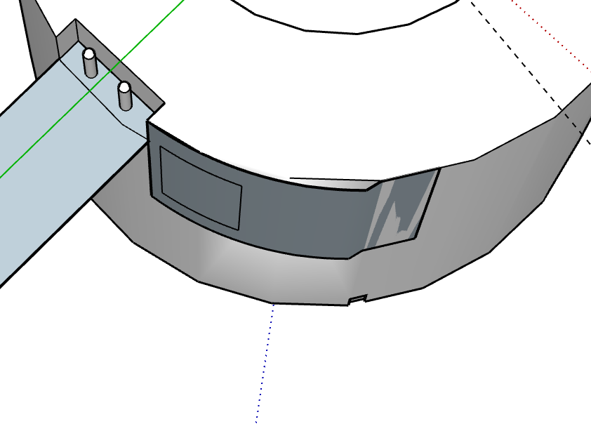
That allows you to see that the ‘flat’ piece isn’t a constant curve when bent.
Towards the right, you have ‘z-fighting’ where two faces coincide, and the OpenGL rendering dithers over which face to show.
Redraw the ‘bent’ piece, and space it a small distance off the solid curve behind it.
Yes, what you have shown is the “feature” i want wrapped along the black cylindrical body. I created the curved feature by making rectangles to the specified dimensions and then using the ‘true bend’ extension to bend the feature to a radius matching the larger black cylinder.
the feature is supposed to be representing metal wire contact points, which are apart of the body of the cylinder. In sketchup, however, I don’t care if they’re the same object or different ones. Just as long as the bent feature is on the outside of the cylinder, and touching the cylinder on all points on the face coincident with the black cylinder’s wall.
is there a way to tell sketchup which object/construction gets priority when the coinciding faces begin to “z-fight”?
No. That’s why you need to space one off the other. More space if you are viewing from a distance, less if close up.
I’ve just looked again at your model. Another possibly contributing factor is that your ‘cylinder’ isn’t cleanly drawn. Still in monochrome, I turned on ‘View/Hidden Geometry’ and get this:
If I delete any of the diagonal lines, I lose part of a face, so they aren’t flat.
You’ve introduced some distortion in the cylinder’s faces when editing, I guess. And one of the top edges has been softened, and it looks as if that was unintended.
IF all those faces of the cylinder were flat, you could draw your additional piece directly on them, I think, either as part of the “cylinder’s” geometry, and texture that, or at least make it easier to get a well fitting separate bent piece to show what you want.
Is there a way to just draw on the face of the larger cylinder I’m trying to wrap the 2 rectangles around?
Yes, but you’d need to clean up the cylinder first.
Looking at it from another direction, I can see where the distortion probably occurred.
That thin sliver in the opening isn’t square with the top face.
I was able to delete a couple of those spurious edges, correct a number of reversed faces (showing grey-blue in monochrome), redraw the distorted faces,and make the cylinder into a component, giving this.
FOR_SKETCHUP_FORUM partly fixed.skp (243.5 KB)
Now you could draw what you want on the cylinder’s faces.
You should get into the habit of making components as you go, and giving them sensible and meaningful names, not just the default ‘Component#1’, etc.
Try never to leave ‘loose geometry’ (things drawn that aren’t in a component or group) in your model after you finish drawing a new piece.