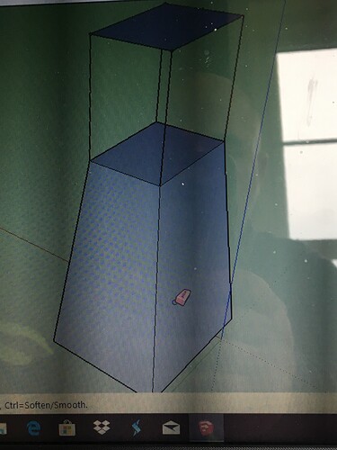
I am trying to draw this in 2D but it’s not working like I want it! Is there any way I can do this in sketchup?
The idea of 3D model software is more or less to have one dimension more the the traditionally paper drawings, so you would have to eliminate one.
Camera->Parallel
Camera->Standard views
Try to see what the View->Facestyle settings can do for you, too.
Don’t get me wrong I like the 3D view but I am building this out of 1.5 inch angle which I can not for the life of me draw it ! I was just wanting to do lines so I could kind of figure the material and see how many sticks it would take me!
3D is easier for what you want to do,
add the .skp file to a reply and I’m sure someone will show you the steps…
john
It isn’t clear to me what you are trying to achieve. If it is just to produce traditional 2D elevations and plans of what you have drawn then @MikeWayzovski’s suggestion is the way to go. But as you must already know the lengths of the various parts to have been able to draw them, a 2D image won’t tell you anything new. Also, the angles mean that a 2D dimension image will not tell you the length of a corner piece (which I assume represents the outer corner of an angle iron).
The answer to your actual question is yes, there is a way of doing it in SU. The standard method would be to draw a section through your angle iron, orient it appropriately and then extrude it along a defined path using Follow Me.
It should take no time at all to figure that without doing any more drawing than you have. On the other hand a 3d model can help you figure out more about the actual
construction.You draw a 2d profile of the angle cross section and extrude with push-pull. From there you can make any length you need to build a model. You can make your measurements in 3d.
I would kill to see how you modeled that
We don’t want a killing now! For right now ( I do have to get to work on more boring stuff) ![]()
I drew one profile of an angle iron with thickness and push-pulled it for length. I determined what my pieces are in length and pulled out copies of the first pushpull and made them components, coloring the faces. For one length you only need one component and make copies of it.
The two outer frames might have bee created with the profile and “FollowMe” using edges of the correct dimensions as the path ( I would then have to add some of the miter edges). Or they could have been the same push-pull shapes that I mitered afterward, to give each piece separately.
Then it is just a manner of assembling–duplicating, rotating and moving the components. Since I don’t know the actual tolerances for this kind of work. I may have adjusted the lengths while assembling to account for the radii of the angle iron.
Your shape is more difficult because of the angles. To position the pieces you need to learn the rotate tool more completely.
Are you using profile builder ? And I am guessing you have a extension for them welds ?
No it’s Just all modeled. Extruded pieces. I probably made one and modified it for each component, and moved it into place. the welds were made using follow me. First I made a full round shape like a pill capsule, using FollowMe on a circle, and then took a quarter of it.
Certainly would use some plugins if I did a lot of this. It was one job and didn’t take much time. Somehow using basic tools was more straightforward than figuring out how to apply plugin. So I could concentrate on the assembly.


