I have been adding some major internal components to the Viking '75 Mars lander 3D digital model, including the large Equipment Plate that spans most of the upper interior of the lander. The Equipment Plate is a one-piece aluminum machined unit which is supported by nine titanium fittings attached to the sides of the lander body. Most of the lander’s interior equipment (batteries, power control, tape recorder, science instruments, computer, communications assemblies) are bolted to the bottom surface of the Equipment Plate and hang down below it within the volume of the lander body. Here is an overall view of the lander body and equipment plate, without the lander’s top dust cover.

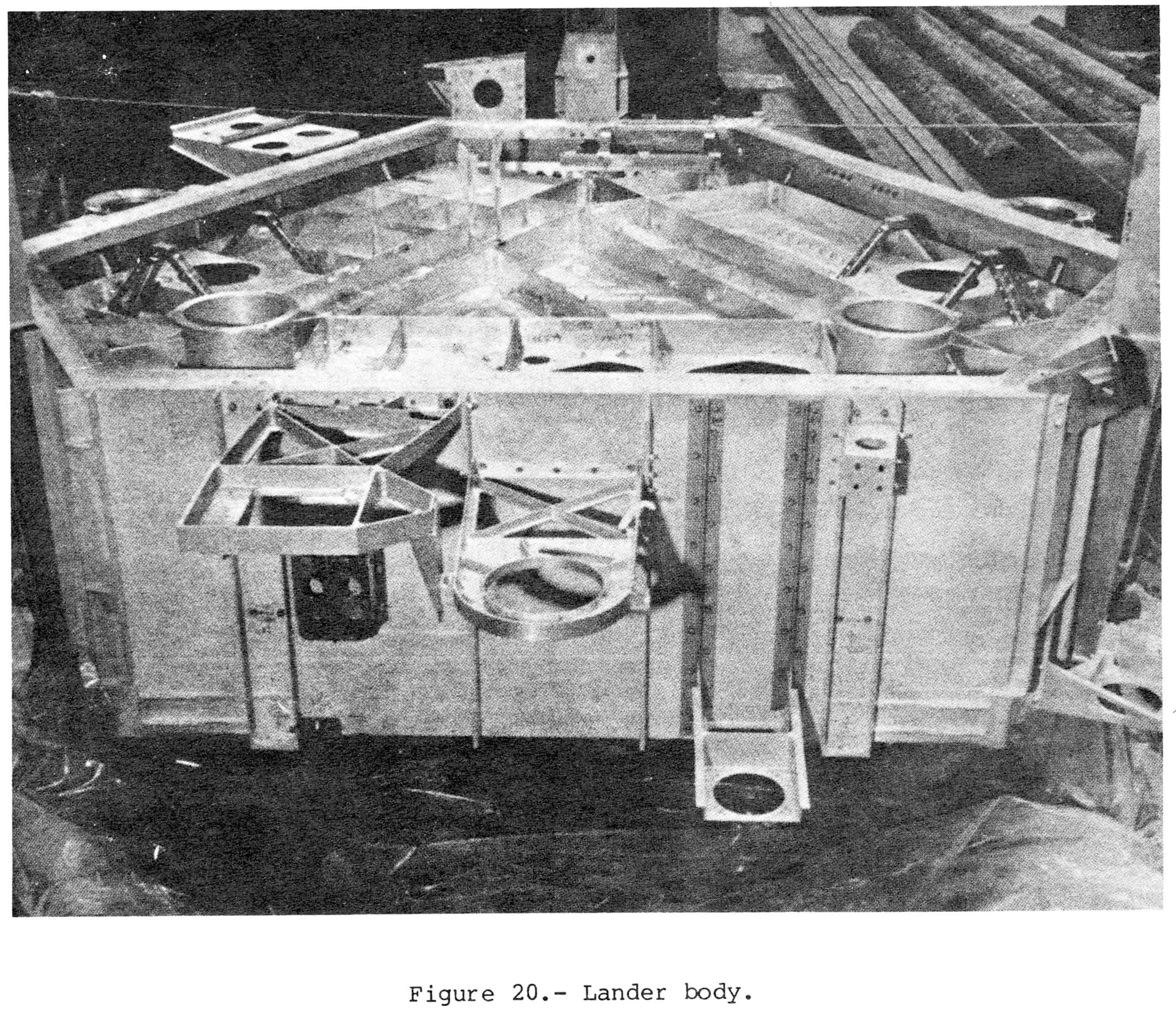
For reference, here is the only historic image I have been able to find (after a lot of searching) that shows most of the top surface of the Equipment Plate:
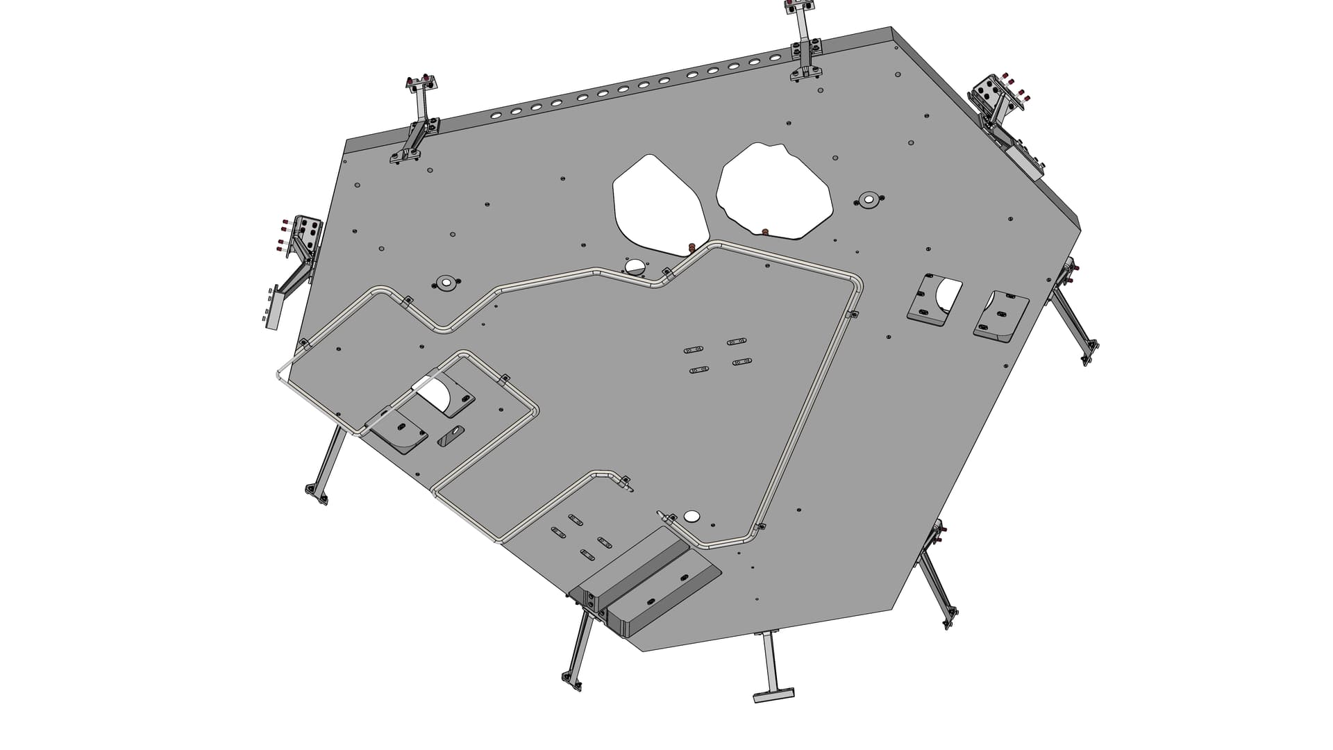
Here is an above view of the equipment plate and attached components, including those nine titanium support fittings arranged around the plate’s perimeter. The 19 little red vertical cylinders are standoffs to support the lander body top dust cover.

Here is a below view of the equipment plate, which is relatively plain. It does show the portion of the serpentine coolant loop which was attached to the underside of the plate. The coolant loop was used prior to launch to circulate chilled water around the lander’s two Radioisotope Thermoelectric Generators (RTGs), which produced more excess heat under Earth seal-level conditions than the lander was designed to sustain. As seen here, the loop also traveled around the equipment plate to reduce internal lander temperatures. The two large irregular cut-outs near top-center allow the soil inlet hoppers (Processing and Distribution Assemblies or PDAs) for the Biology instrument (left hole) and Gas Chromatograph Mass Spectrometer (right hole) to pass up and out through the top of the lander. The lander’s Surface Sampler Assembly (subject of a separate forum post) would scoop up Mars soil samples and deposit them into those inlet hoppers.
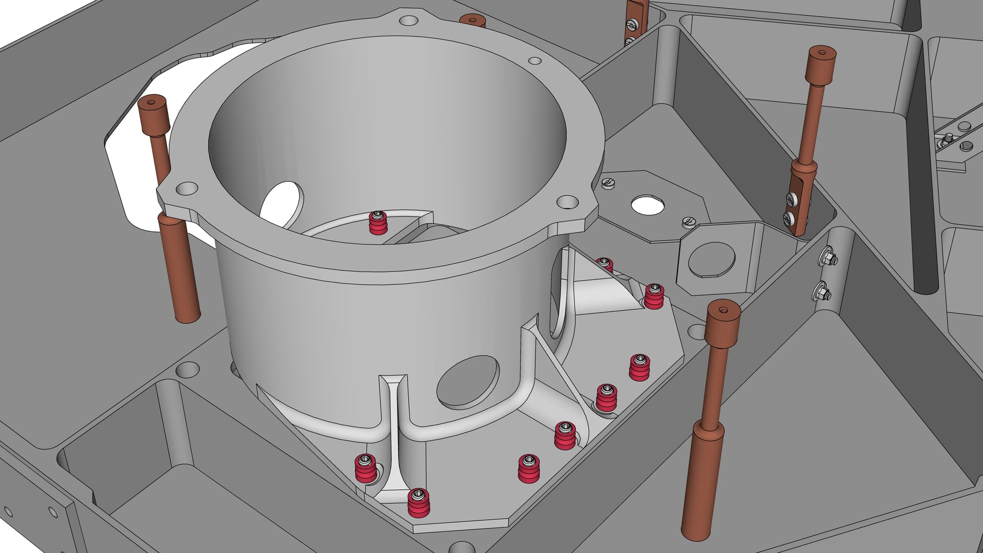
Here is a detail view of one of the two camera mount adapters bolted to the top of the equipment plate, to which a camera was attached on top of the lander (this is the mount for camera #1). The little red fasteners are Hi-Lok collars, a specialized type of nut that was used extensively in assembling the lander. The collars work with Hi-Lok pins, a type of bolt. Along with a special installation tool, the Hi-Lok pins and collars can be installed in situations with limited access to the bolt-head side of the fastener. The tip of the pin (where it protrudes through the collar) has a hex recess; the installation tool uses this to prevent the pin from rotating when the collar is tightened. Look closely and you can see those hex recesses.
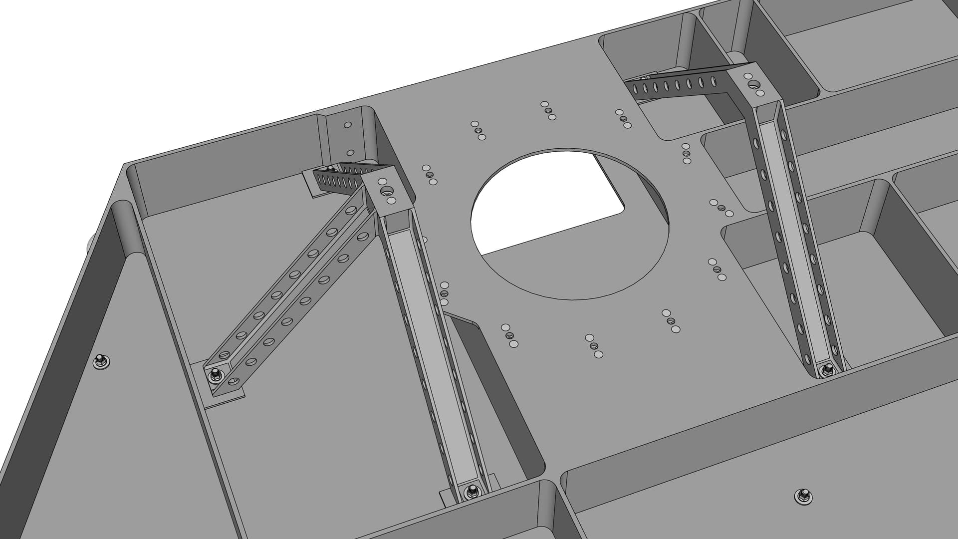
This detail view shows a small tripod and bipod attached to the equipment plate’s upper surface. These supported the inboard side of RTG #2; the outboard side was supported by the upper edge of the adjacent lander body side beam (not shown in this image, but visible in the first image above). A similar tripod-bipod pair for supporting RTG #1 is located across the equipment plate.