Measure miter angle for curved hood

Yes. Regular glues require closely matched surfaces to work. They will not fill gaps. And, don’t be misled by the way polyurethane glues foam up and fill gaps. There is no strength in that foam!

I downloaded your model and worked from it. I don’t know why we got different values. it’s possible I botched some detail…but you get the idea.

Edit: Yep. Revisiting @DaveR 's animation I see that I didn’t measure the angles correctly. The guide in the front face needs to be perpendicular to the edge of the board because that’s the cutting path of the saw. I should know better :flushed:

Edit 2: After screwing my head on right, this is what I got:

Note that it is important to measure at the joints between the boards, not at their middles because the largest and smallest angles happen at the joints. Cutting to the middle angle will produce gaps at both the inside and outside!

Edit 3:
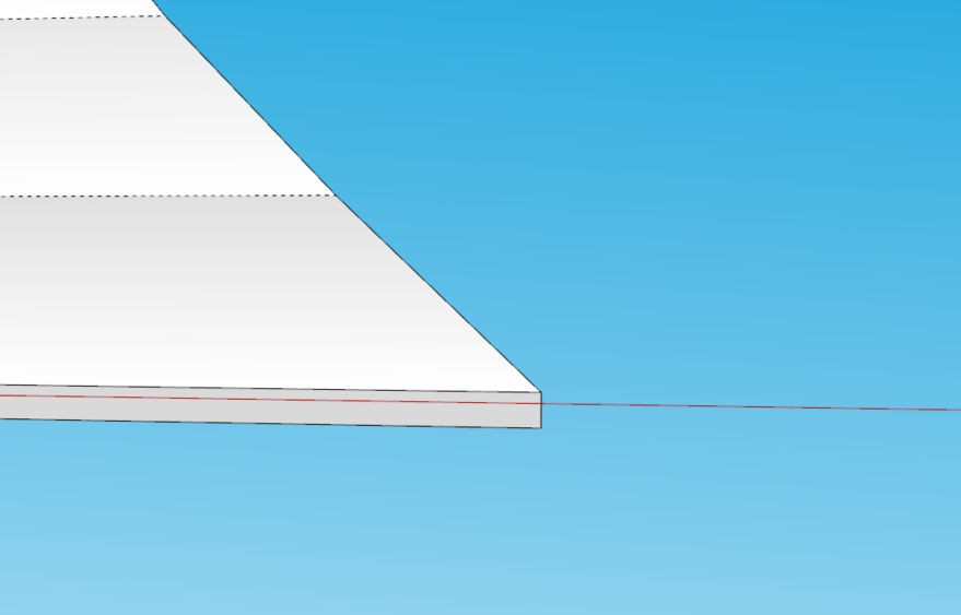
Also note that there are two bevel angles at the joint between two boards, one for each of them because their surfaces are not parallel. The difference in this model is quite small, but it is there. Here I drew guides for both the second and the third board and marked their angles. I also marked how the guides are perpendicular to the respective edges but are not quite the same. That’s the nature of the “rolling bevel” we were writing about earlier when the surface is a sequence of flat faces rather than a true curve!

1 Like

Click in sequence on the scenes tabs of this SU file for ideas.

Hood part.skp (315.2 KB)

I would offer a perhaps more straightforward approach. Think of this surface as something like crown moulding. If you bend the sheet to the desired curve, it can be cut on at a simple 45 degree angle. Think old fashioned miter box. You could probably make the cut with a handsaw and maybe one of those inexpensive lasers projecting a line. I’ve done this in the past with cupola roofs but only for sheathing.
Might be worth a try.

Same sort of thing I was describing but I laid the front panel down so it would fit through a reasonably sized bandsaw.

Projecting the deformed plane to a flat surface (‘tracing’) would circumvent the need for a specialized jig or needing to know any particular angle along the edge of the deformed plane. But does it work?

I took an example of the hood and flattened it (The jean_lemire hood from above):

Screenshot 2024-02-09 042103

The angle changes across the length of the cut:

As ‘proof of concept’ for projecting and cutting this at 45 degrees to start with, I ‘repaired’ the edge with a 90 degree outer edge and then used Solid Tools Subtract to recut the entire length at 45 degrees.

90 outer (the cutter):

New 45 cut:

The flat projection was then deformed back into the hood shape:

The little artifact on the bottom gives and idea of how much more would be cut off vs the original.

I don’t have a dado, so I did a mock-up that starts with a projected edge cut at 45 degrees:

If that is then curved back into the hood shape, shouldn’t it fit? And shouldn’t it fit with sides cut at 45 degrees?

Quick example of kerf cut projected edge cut at 45. On right was not curved to match the hood curve section shown in front… because, ‘oops’.

The reason I’m so stuck on the idea of tracing/projecting is that cutting the flat piece at 45 degrees seems way easier, with less chance of bad cut/fit, than trying to cut this while it is curved. It seems simpler and doable!

This hood is a great little puzzle.

I’m blown away by all of these great replies - thanks to you all for that!

slbaumgartner - thanks a lot!
I just want to clarify to make sure that I understand you correct: I will be making this hood cover from one piece of plywood that I will kerf cut on the backside to bend, so there will be no boards joining together. Was that what you mean with the EDIT3 (?). Or is there still something here that is relevant if I do it from one piece?

jean_lemire_1 - thanks a lot for the step-by step!
To be sure that I get you right; what you are showing is that the pieces will fit together if they are cut while they are bended, and then you suggest that I bend the piece before making the 45 degree cut, so that I do not have to try to align my cut edge with the blade to cut the 45 degree (so doing the cut and bevel in one step)?

Shep - thanks a lot! That is also a great idea although it make take a little practice to be so precise with the hand saw. I guess you call it ‘skills’ :smiley:

3DxJFD - thanks a lot!
Wow - that was a really good explanation of what is happening!

In one of the steps you say this:

The little artifact on the bottom gives and idea of how much more would be cut off vs the original.

Is this the little artifact that you refer to?
2024-02-09 12_51_44-Measure miter angle for curved hood - SketchUp for Web _ SketchUp Free - SketchU

You also write this:

Quick example of kerf cut projected edge cut at 45. On right was not curved to match the hood curve section shown in front… because, ‘oops’.

What do you mean by that?

I agree with you that it would be far easier to a 45 degree bevel on the flat piece before it is curved.
If I understand you right, what you show is that it is actually possible to do it that way and still get a somewhat nice fit?

My aplogies! My OCD brain got so fascinated with calculating the rolling bevel angles that I forgot you intended to bend this from a single sheet! I was treating the smoothed lines between SketchUp’s representation of a curved surface as if they were the edges of actual planks (which would be a different way of making the hood).

However, the rolling bevel angle calculations show that if you lay the plywood flat and cut the edge at 45 degrees all the way (as suggested by @3DxJFD) , there will be a substantial gap to fill at the bottom, where the bevel should be more like 55 degrees. Also, you will have the challenge of cutting the bevel along a curve. You could do that with a band saw or a jigsaw, but not with a circular saw.

I you were to try one of the upright jig ideas, by my calculations (which at this point I suppose could be suspect) you would need at lest a 37cm diameter blade - larger than most table saws use - or a large bandsaw.

Yes. There was a little doohickey there that I didn’t see at first.

You can see the original is a 90 (the ‘bottom’ is the face):

Here it is flattened (and so now the bottom):

This is a view looking down at the 90 (the ‘artifact’):

In other words, it was 90. Now it’s 45 (on the flattened hood).

Also, because we started with the deformed shape, it’s as-if the gaps where the kerfs would open up are filled in. So when the curve is laid flat again (rotated), the back ‘pieces’ overlap:

This makes the curved side look like a mess too.

But we know that actually a curve would be filled-in if it where cut, because it would be a smooth curve. The reason those are there is the length of each segment:

Those were cut off with the 45.

I drew the kerf piece before I used Jean’s template. So, I rotated however many at a time, 1 degree or so. And the edge curve is not a projection of the example hood. To match the face curve of the example model I would use the section plane shown and rotate the face to it. In other words, I woke up in the middle of the night and was still bothered by how to get this thing cut and didn’t finish.

I see another post indicating that ‘projecting’ might not work. I do know that you’d have to offset for the material thickness, which I think can just be an inch. I think the people saying to do it like a big miter cut are correct: you could bend the piece into place and shoot a laser at it. Then trace the laser line. Then lay the piece flat and cut a 45. When you curve it back into place all of the curved segments should ‘deform’ back into place again. Or not :slight_smile: That’s the puzzle.

I may try to do the projections of the example hood for the face and a side to see if it fits. The outer faces should be good. It’s butting the inner (deformed) 45s of the face and side, once they are curved back into position that I’m not sure about.

I’m on the go, so will return to look at the reply - just want to mention that I am unsure if the curve in jean’s example is an exact copy of mine or if it is redrawn - just mentioning in the case that you are trying to work more in it!

Will get back soon!

Think of this as building a Hip roof. You need to frame it as such. You have a component described as a “stiver” Google Translate suggests this is Danish for “stiffen”. I assume making it a noun and you have “stiffener” Lets call it in roof framing a common rafter. What you need on the front corners are stiffeners also. Known as Hip Rafters. Your common rafters (stiver) are based on the Rise and Run. The run is 18.3 cm and your rise is 55 cm. Then you have tossed in an asthetic curve of your preference to make it a little more tricky. Do some research on building hip roofs and make the framing of your design so that it mirrors such construction with top and bottom plates. There are calculators online to determine a Hip rafter. It’s result will give you the basic length needed or with this small a unit you can just measure it. Frame up your piece with rafters only. Then run sticks horizontally like roof strapping. Attaching them temporarily to the rafters. Keep them long on the whole face of the front from top to bottom with gaps in between. Do the same on the ends also with the sticks fitting between the front face sticks. Play around with it and you will see how you need to carve the arc into your Hip rafter. When you have figured it out, then you will have to cut the Backing Angles on your hip rafters. This is so you have a flat surface to attach your plywood skin. On this small a piece you can carve the backing angle with a orbital sander. It doesn’t have to be pretty as it will be hidden When you glue and pin the skin on.
There is a free extension called “Unwrap and Flatten” which will help you alot. I ran it on the face of your skin. See the results in the attached file.
3.skp (296.0 KB)

2 Likes

Yes exactly.

Plus, you don’t need ‘kerfed ply’ , 4 mm thick will do!

Thank you all for the great inputs!

After thinking a little more about this I am not sure that I would be able to cut it while it is curved because of the available tools and the risk of working with the big pieces upright. But I think that this was a really inspiring discussion, so thanks for that!

What I see as my possibilities now are the following two scenarios:

1: I ‘redesign’ the hood pieces so that they will not have a 45 degree miter, but instead just ‘flat’ edges. Then I will make the two side pieces a little shorter and let the face piece lean against them. I will assemble the two side pieces first, hold the face piece in place, scribe where they meet and then lay the face piece flat and cut it. That would require some sanding and filling, but do you think that approach would work or is there something with the curves that I have not thought of?

2: I try to find someone with a CNC router to cut it for me.
But with that approach I have the following questions:

2.1: How do I export a ‘3d’ file that can be used with a cnc?
If I export to DXF I will just get a ‘flat’ file with the shapes, but I guess I would need a ‘3D’ file to also show the miter.

2.2: How do I lay the piece flat in 3D? I can use the "unwrap and flatten faces’ plugin, and that works great if I only select one face. But how to flatten the pieces when I also need to show the bevel?
Or is it not even necessary to flatten it if I want to create a file for a CNC?

Thanks for all your great inputs!

PS - should question 2 be a separate topic?

I tried to solve the problem pointed out by Steve by doing the flat projection and then cutting from the face side, bottom, at 39 degrees, to about halfway up, then transitioning to a 45 degree cut halfway through to the top. That should have gotten rid of the gap on the inside bottom, reduced it in the middle and then closed it for the top 45 degree section. But I had a little error and couldn’t convince myself that the result would be any better than just trying to fill the gap in the back after doing the 45 degree cut.

As for butting the back pieces to the front: isn’t there a ‘law’ against showing cut edges? The outside edge of the front would also have to have the kerf cuts filled in (if that’s what you were going to do to bend it). So, you’d have a cut edge with the kerf cut outs to fill in. That doesn’t seem right.

Anyway, I’m resisting YouTubing/Googling hoods… hopefully you’ll be posting on how you end up doing it.

@3DxJFD thanks for the reply!

I’m not sure why you would start at a 39 degrees at the bottom (?). If I’m measuring corectly then the bottom should come out at about 55 degrees and the top at 45. So at 39 degrees, the front faces will not meet because not enough back material is removed (?).

So if I cut it 45 deg all the way when laying flat, then I would ‘just’ have to manually remove a little more material at the bottom to ‘open up’ the cut a little more, is that correct? I think that could be done with a little sanding as I guess it would be very little taking the 15 mm material thickness into account?

I will definitely return with a conclusion once I have decided how to do this!

Edit: and yes, you are right about the rule of not showing cut edges. It will be painted, but even if I fill in, paint and sand, I will be worried that you can actually not hide the layered structure of the plywood 100% (only if adding fine veneering). So that really narrows down the choice to either cnc or filling in the gap at the back!

Edit 2: I’ve used hours googling and youtubing hoods. Other approaches I have seen is to use thin mdf or 4 mm special bendable ply. I am not a fan of MDF due to the moisture from cooking, and I do not have access to 4 mm or special bendable plywood!

Shucks - I did mess with this a lot. It’s fun but harder than it seems. But I didn’t save anything. So, if you cut the length of the curve (with the face side up) with your saw set at 45 degrees there is a gap on the bottom that would need to be filled-in on the lower portion of the hood. The top fits together. The outside face fits together regardless of the angle (unless you leave too much and need to sand it off - but that’s a different problem).

So, without even showing anything: if cutting away 45 degrees creates a gap on the bottom that is too big, how can cutting away even more close the gap?

Are we thinking about which side is the “take” and which is the “leave” differently?

For example, my jigsaw can tilt to 45 degrees (I realize the other side is therefore bigger). My circular saw can tilt to 50 degrees. So, I guess I don’t think of how I set my saw at 55 degrees. I’m thinking, ‘how do I leave more to fill the gap’. In other words, how do I cut less than 45 degrees.

Alright, so the error I mentioned was this:

I copied that from the 3.skp. Because I started at the top… I didn’t realize it until I got to the bottom, made flattened versions, put an angle on… and then went to put it back together and saw the overlap. Ah crud moment.

So looking at it again, the bottom of the face sheet is cut lengthwise (from side to side to sit flat on the frame, I guess). To measure the angle I squared that up to a ‘factory’ 90.

Just showing this for completeness… to me, the bottom was ripped with a blade set at 34.6.

Now for the edge that matters, I moved the 90 edge over so I could see it overlying (overlain?) on the angle (I only copied the lower part of your ‘sheathing’ - that’s why it looks small).

The diagonal line is the edge of the angle shown on what would be the bottom edge of the sheathing. That is how I came up with 39 degrees.

For reference, here is a guide on 45 degrees:

The ‘meat’ in between the 39 and 45 is the filler that closes the gap. So, if I set the saw on top at 45 degrees it would be the dashed cut and if I only tilt my blade 39 it leaves the filler.

So, I was trying to say you could cut from the bottom edge of the hood at 39 degrees ‘about’ half way. And cut from the top of the hood at 45 degrees. That would zip the backs together. Sorta, kinda.

You have to dispel my confusion! I want to know how to cut this thing.

Why would you use these materials for a hood over a cooking surface, they present a huge FIRE HAZARD.

2 Likes

@3DxJFD thanks a lot for the explanation!

Yes, I was thinking about the angles differently, so that is why I was so confused.

I agree that if you cut the hood from the front face, then an angle of 54,42 deg at the bottom will leave more material than an angle of 45 deg at the top. So thanks for clarifying that!

So, using the angle between face plugin I get this angle at the top (approx 45 deg):

And this angle at the bottom (approx 54 deg):

Since my saw can only tilt to 45 degrees, and since I will cut it from the front face, then I think my angle will be: 90 deg - 54 deg = 36 degrees - is that correct? But you are coming to an angle of 39 degrees? I really tried to follow you explanation in the post, but I’m not sure I understand.

IF that is correct and I chose to vary the angle in the cut and not just cut it 45 deg all the way, how would I then measure the points where I should change my angle? I can lay down the front face flat using the Unwrap and flatten faces plugin, but I would need to lay down not just the front face but the whole 3d object to be able to measure the angles and the distance where it transitions to another angle.

Regarding the bottom side of the hood - you get an angle of 34,6 degrees. I would really like to try to replicate that measurement, but I don’t get how you measure it. If I look at my model it is of course already flat 90 deg because I drew it that way, but you are right that in reality, it will need to be cut to an angle. I’m just confused to what would be my reference angle to measure the cutting angle.

This is the newest file.
2 (2).skp (313.5 KB)

If I get this right, I’m starting the cutting process today!

1 Like

Maybe I got it wrong? Keep in mind that your example piece has a ‘cut’ across the length of the bottom, so it’s not ‘stock’ 90. Double check that you’re getting the Protractor tool set correctly. I also don’t have the plugin you mentioned.

I tried figuring that out but I couldn’t do it. I tried adjusting the path of the curve in a couple of ways… rotating from top, cutting from inner face, etc… I ended up looking at the model with a 45 across the entire thing and just eyeballed where the gap closes as the cut moves towards that top.

If I recall, the number of segments in your curve was 12, so it’s ‘as-if’ you have 12 ‘boards’ (each segment of the curve and the hidden lines across) making up the sheathing/panel. You could measure those out / lay those out from the bottom on your piece as a rough guide. Also, if you use the Solid Tools you do have a ‘correct’ cut model and you could measure the angle every few inches (as-if they are ‘boards’) and adjust your saw as you go incrementally.

I did it manually. I created components out of every ‘board’ (edge in the curve) making up the panel and rotated them. I don’t know if that extension makes small changes. But it does have to change the shape so I’m suspicious about the result. For example, the ‘boards’:

Overlap when lain flat:

The extension would have to account for that somehow. Did you measure the angle after using the extension? Maybe that is why we have different results?

I ‘rebuilt’ the factory 90 over the cut. Then I pushed it or moved it over so I could see the cut against the 90.

Also, are you measuring the angle ‘square’ off of the line segment (edge) of the curve? I moved component ‘boards’ to the model axes and rotated them flat to make it easier to see where I was putting the protractor. Others seemed to be able to get the angles in situ but that was confusing to me.

So I guess if you know that your top is flat, a 45 marked on the 90 degree edge is correct. Then from the bottom if you redraw your 90 and mark your angle (which is what you’ll have in reality) the blade will sweep through at the correct place and then you just have to cut off the bottom so it can sit flush.

A few more things. I noticed that the thickness of your material was a little unusual. Is it what you want? Also, the previous models don’t fit together properly. In one case there is a slight overlap of your front and side panels and in another the curved support pieces are not placed correctly (or the panels are inset). Best to make sure those are squared away so you can count on them.

Go to Window → Model Info → Units and uncheck Enable length snapping. This causes people all sorts of trouble. Save a temple with that turned off. You might turn off Enable angle snapping as well. I don’t know if that is a problem… but it might interfere.

v 2(2).skp

Screenshot 2024-03-15 035555

I think you should expect to make a number of test cuts. Document how you do it each time and see what works. I’d personally be interested to see even a bad result or two as that might be the path to getting it right. If you master this you’ll have a great skill!