Realistically if you are modelling to real word sizes, as you should be, and typing in those dimensions as you go, things should work out. But if you have a length of timber/lumber that is roughly 8feet long and you divide it by 9 the divisions will be what they are, and if you have set the ‘display precision’ to show a coarser dimension than needed you will get errors.
By the way, with 1/64th inch display precision the sum of the minor dimensions is 232.5002 in. The overall is 232.5000 inches. ALL of your discrepancy is round errors due to setting the precision to the nearest 1/4 in. I would bet my lunch money for the week that the contractor will not hit 232.5000 inches for that outside dimension.
FWIW, you could leave the display precision set to 1/64th in. It won’t show 64ths or 32nds unless that the way you’ve modeled things. This is a great example of why I advise people to do their modeling in SketchUp with Display Precision set as high as it will go. That allows them to see potential errors and deal with them before they become a problem. Dimensioning in LayOut can be done with coarser Display Precision without inducing rounding errors if yu know the model was created precisely.
Box, I typically place windows and doors by drawing a polyline across the full length of the wall, and then use the divide command to split that line into the appropriate number of divisions such that the midpoints of any openings will be evenly spaced for aesthetic purposes. CAD and SU both allow lines to be evenly divided, both using the divide command. It makes logical sense that CAD should have been producing exactly the same errors, perhaps I did not notice. In future I will use the same method, but then slightly move the door/windows such that they fall on an even multiple of the display precision (1/4").
Dave R, you must be correct that I simply did not notice any error of that type with CAD, despite a long history of using it. The end user of these plans will actually be constructing these wall panels off-site, and then assembling them, so the exact dimensions of not only the center, but also the studs themselves will be noted on a panelization plan prepared for each 10 foot section individually. For that reason, I will need to either model the apertures on a 1/4" grid, or increase the precision of the dimensions for the framers within the factory to use.
I will simply ensure in future that all objects subject to dimensioning will be on that 1/4" grid.
Do you have any additional advice knowing the approach?
Also, I do all floorplan modeling in AutoCAD Architecture, and then import the linework as a dxf into SU so that I can then model the walls by simply snapping to that linework to draw in the walls. I will have to use a very high precision in AutoCAD, in order to make sure these dimensions will work out after import and modeling in SU.
I use CAD for floorplan design because it’s tools are much quicker for me, due to experience.
I won’t take more if your time as the issue has been resolved, thanks for the advice.
It’s one of those things where people design something, in the old days on paper, then the carpenter gets the wood and it isn’t the exact dimension so they have to adjust for reality.
In the same way you need to be aware of what dimensions you are actually working with if they are related to real world objects.
Simply stating ‘I’m using 1/4 inch’ doesn’t guarantee accuracy.
CAD, SketchUp, etc - none of them magically create your model to handy to use dimensions in the real world. That is your job …
If you are bringing in DXF I would bet you are compounding on compounding errors.
It’s entirely possible that some of your imprecision is actually being imported with the CAD file. Make sure you have Length Snapping turned off and, as I wrote previously set display precision as high as it will go in SketchUp so you can detect those small precision errors. Decide if they are critical and need fixing or if you can leave them. Treat them accordingly.
Also look at the dimensions you are putting in on your drawings. Put in the critical dimensions and, also I wrote, don’t create conflicting dimensions.
Most of my commercial work with SketchUp and LayOut is for woodworking and machine shop projects. They require much higher precision than 1/4 in. but it’s not a problem to hit that precision.
SU imports the dxf quite accurately. If I model it accurately in CAD, it will be modeled to that same accuracy within SU. The source of the dxf just must be congruent with the dimension display precision.
I cannot say how this issue never popped up using CAD alone, but whatever, it is understood now.
Thank you much
So I’ll be curious what you find for where this disconnect is coming from.
Do you mind sharing the DXF?
I modeled the dxf on 1/4" display accuracy so it makes perfect sense that the rounding error would show, the dxf had exactly the same issue as the SU model. I don’t have the dxf on my current workstation, but after getting the actual work I need finished today then certainly I will. I’d like any advice on that workflow I can get.
It’s been a long long time since I used ACAD - I’m not remembering how display accuracy would affect what you draw. For me, back when I was using ACAD every day display accuracy only came into account when we had diagonals or intersections with curves - other geometry (compound roofs, mainly, in my case).
If you draw the rectangle outlining a foundation do you start a line and type the actual dimension you want it to be? Or are you relying on the software?
May I use your screenshots to illustrate the problem with creating conflicting dimensions for a bunch of high school students on our local FIRST Robotics team?.
Getting a green endpoint snap in Layout does not guarantee that you have attached your geometry to the model. Just draw a line in Layout and attach a dimension to the endpoint of that line. You will find that Layout finds an endpoint green snap on that line also. So in essence it is risky to add a lot of linework in Layout around your model, exactly because you cannot be sure whether your dimensions are anchored to the model or not.
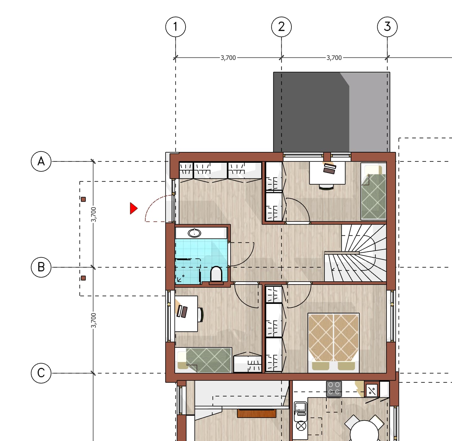
For this reason I will have my grid lines in the sketchup model, like in the attached image, and I dont have the problems you describe of having dimensions randomly change.
But a green dot means the dimension is anchored to something on the page.
I use AutoCAD Architecture, so I draw using a wall type, typically with 1/2" cladding, 1/2" sheathing, 5.5" stud, and 1/2" Gypsum. I type in a round number for the wall length typically. Then I add in the windows and doors at whatever appropriate size, but I do not type in ANY measurement for their exact position, which is the issue. Instead, I draw a polyline, and then use the divide command to evenly space reference points along the wall length. I then snap the window or door object to those points. That was the error here. Instead of a round number congruent with the eventual dimension, they are at an arbitrary spacing that is equal.
With the foundation itself I also draw using a wall object, ensuring the lengths to be multiples of 8", so that only every other course will require splitting block on site.
I truly cannot say why this method never produced a noticeable error within CAD, likely just my failure to recognize those errors, I cannot think of any way that CAD would have been able to compensate.
Certainly
Thank you.
Thanks, I actually added in planes on a specific layer within the sketchup model to represent the different elevation points, Finish Floor, Roof Plate, Gable Top, etc.
For the xy dimensions, I made a separate scene with all extraneous elements turned off, so that in Layout I would click on the proper spot. This has resulted in green snaps so far today, and so far no dimensions changing from model to paper, which was my original concern.
I would like to be able to use dimension objects to do calculations, as in CAD model space, that is the only deficiency at this point. The others are more the result of my inexperience. In CAD, I don’t need to click on anything, but can just add a string of dimensions in empty space, and then another along their entire length, to check for instance, a full wall height number when I know the constituent elements.
yes. And a dimension line will show model measurements even if only one of the green end of line snaps are from the model, and the other is a line in Layout.
So that would be a safe way to dimension something only if I made sure that the relationship between the Layout linework and the viewport always stayed intact.
I have some dimensions here that are coming in as paper space lengths, although those objects do not exist in paper space. I have green snaps, but paper space measurements. What am I missing in this under 1 minute video here?