This mostly works. The Geolocation is lost, but can be replaced.
However all the elevations come in as integer meters. LIDAR is more accurate than that and I would like to make use of the accuracy.
One approach I have looked at is translating from the LIDAR .asc dtm file to the international SDTS .ddf format which supports decimal elevations and can be imported by Sketchup. But I am unable to find a tool to do the translation.
(In the UK, not sure about US, DTM stands for digital terrain model, a cleaned up DSM or digital surface model eg DSMs show house roofs, DTMs don’t)
Kind regards
Mouse
First few lines of LIDAR DTM .asc file below. The rest of the file continues with more point elevation values and a newline every so often. There is no terminating string. Values are in meters. Geolocation ‘x||corner, y||coner’ is an UK Ordnance Survey grid reference for a corner of the area covered. Cellsize=2 gives the 2m spacing of values.
Hi mouse,
I’d be interested in this too. I produce dtm’s From Pix4D from my drone surveys, currently I only use the Orthomosaics instead of the SU Geolocation terrain imagery for hi-res 2D site plans in SU, a method to get elevation maps in straight from th DTM would be awesome. Currently the on;y way I can think to do this is to generate the contours in Pix4D from a DTM (which it can do) and the use those in a SU TIN. Not ideal but doable. I assume you want to use the free OS LIDAR data(which is available in 1m resolution in some locations!).
I am trying to use the UK Environment Agency Open Data LDAR DTM, which is in 2m at my location.
The workflow I reference passes the DTM through microdem, which can save as USGS ACII DEM file which Sketchup can read. Unfortunately the USGS DEM standard defines elevation as a one or two byte integer, so importing from a USGS format file in SU will likely never be any good.
SU can import files formatted acording to the international standard, STDS (.ddf) files which does allow decimal elavations. But I can find no program ATM which can import LIDAR DTM .asc files and export STDS files. Any thoughts?
Here is my initial workflow for UK Environment Agency LIDAR 2m Composite DTMs. Not as bad as it looks - After installing the software, I can run through it in 30m. Please do test it - I have run through it a couple of times but it needs more testing
It should also work for 1m and 0.5m EA Lidar DTMs though I have not tested it. Also for Lidar DSMs. It may work for the so called LIDAR tile DTM and DSM data files. In contrast to the composite files which contain data merged from >1 survey and resolution, the LIDAR tiles files contain data from one dated survey, at one particular resolution. Note however there is likely to be much more missing data in these tiles. The approach will need a lot of adaptation for point cloud files, which as fairly raw x,y,z data from each plane pass, need special software to unpack, careful post-processing to eliminate isleading data, merging, and potentially co-ordinate system translations.
As background and useful info UK EA LIDAR Composite DTMs are in ESRI ASCII raster grid format with decimal elevations (z) in metres, given on a 2m, 1m or 0.5m horizontal grid. The horizontal (x/y) projection is British Grid EPSG code 2770, datum OSGB 1936. The Composite .DSM file gives the surface including buildings etc, the .DTM just the terrain.
I will edit it if I find corrections. Doubtless there is a simpler way…
Take the LIDAR Composite DTM or DSM .asc file for the needed OS 1km x1km tile (eg SO3548), not the one actually described as a ‘LIDAR tile’. Here is the EA site you can also get it from the OS site I think: Defra Data Services Platform
Open Excel and data ~ import the file into Sheet1 as a delimited space separated file
Delete the header lines. Also delete the first column (if it is blank).
Use standard Excel facilities to create a second sheet consisting of these values say x100. (x1000 is too much for Microdem if starting with normal real world elevations eg 100m). I can explain how to do this in 2 mins on request.
Save this file as a straightforward comma separated .csv file, say DTM.csv
Open DTM.csv in a programmers editor – I use Notepad++. Go back to the original .asc file, copy the header information and paste it into the same place in this file as in the original. No blank lines before or after. If you paste header information you cut in Excell, you may need to edit the NODATA value to -999900 due to the way Excell can change data values. This takes 2 secs – don’t worry.
Change the file from Windows End of line format to Unix end of line format. (Edit/EOL format in Notepad++). If no function for this search for CR LF and globally replace by LF in any way you editor supports.
Do a global search and replace to replace commas by single spaces
Open Microdem and choose to File ~ Open ~ DEM and choose DTMprocessed.asc. There is no need to change the projection parameters – it gets the georeferencing wrong anyway. One warning about Microdem - do not use paths or file names with spaces in them at all when using this software.
Optionally use Modify ~ Map Area to crop the tile to the area you wish to use. Save the subset by choosing File ~ Save Subset, and when asked Load subset=OK. It will save it as sub-DTMprocessed.dem.
Use File ~ SaveAs to save the file using File ~ Save Dem ~ ASCII ~ USGS ASCII giving you a USGS Ascii .dem file. Call it DTM.dem. Note that all decimal values will be removed by this process, but due to the multiple (egx100) used this does not matter at all or as much.
Open Sketchup and use the import function to import the file, choosing the file type ”.dem, .ddf”. You may wish to limit the number of points imported prevent lengthy imports – youcan do this on the choose file to dialog by clicking the Options button. 10000 is mentioned somewhere as a sensible limit.
After a while you will see a SU TIN terrain surface at the appropriate seemingly very large !!! elevation – if your land surface is at 100m it will be at 10,000m! It will load at the origin with the NS grid side along the green axis – ie with Grid North aligned with the green axis. The green axis is conventionally NS in Sketchup, It also appears to import at correct x/y scale. Triple Click on this DEM and use the scale tool to shrink it along the z access by the multiple you increased it in Excel, eg using a factor of 0.01 if you used x100. Rescaling may take some time 5 mins or so - so don’t worry.
Right click and choose to soften/smooth edges choosing both options and normal at 90 degrees. Click away and it should look nice.
Optionally reduce the apparent heght of the terrain by resetting the z axis by right clicking and choosing to move z far enough so the lowest point is above the red and green axes as shown here: Adjusting the Drawing Axes | SketchUp Help
I have still not sorted out proper georeferencing. Meanwhile you can copy the tile corner references for the lower left (SW) corner of the tile xll= and yll= from the .asc file and concatenate them as eg “317000 278000”. Go to http://www.nearby.org.uk and type them in and read off the Lat and Long values of this corner of the TIN. The SW corner is the origin in SU, so you can enter these manually under Model Info. I use the default WSGS values so I can xref with locations on google Earth. If this is not an issue for you, you should probably use the OSGB 1936 values for consistency. These are in small text underneath. This plugin should help to place model elements at particular lat/long http://rhin.crai.archi.fr/rld/plugin_details.php?id=737, though I have not tried it yet.
And here is the cleaned up and smoothed subset of that tile model which gives the immediate surrounds of our house. Our cottage is on a triagular plot with a curved lane on 1-1.5 sides, a wall on another, and a ha-ha/hedge in front.
You can see the curved line of the lane round our house and cutting diagonally across, the ha-ha in front of it. The wall has been removed in LIDAR processing as this is a DTM.
The model is agruably a bit over smoothed though the elevations, elevation differences (1-2m) and slope directions seem about right. In reality the edge of the haha is quite sharp, and the hedges beside the road quite vertical. The smoothing is probably mainly due to the 2m LIDAR spacing.
… then possibly the step 14a (before import) may be to set the proper datum.
The default is set to “WGS 84” in the templates shipped with SketchUp.
Weirdly, there is no input box or drop list in any of the Model Info dialog panels to change the datum.
You’ll have to do it from the Ruby console. In the console …
Sketchup.active_model.list_datums
… shows you an array of all the datum name strings that SketchUp recognizes.
You may wish to do this to your favorite template and save it so you do not need to for every model.
Or if you just wish to do this temporarily (during import,) create a menu item in a .rb script …
UI.menu("Window").add_item("Set Model Datum ...") {
  choice = UI.inputbox(
    ["Datum"],
    [Sketchup.active_model.get_datum],
    [
      ["European 1950", "European 1979", "Ireland 1965",
      "Ord Srvy Grt Britn", "WGS 72", "WGS 84"].join('|')
    ],
    "Set model datum ..."
  )
  Sketchup.active_model.set_datum(choice.first) if choice
}
Add or remove whatever datum names you care about. (Change the order also if you wish.)
Thanks very much Dan, a good idea to set the right datum in Sketchup. I did not know you could.
If I set the right datum will Sketchup recognise grid references eg 399401 245899?
It’s quite confusing sorting out georeferencing of LIDAR tiles. They are just grids of elevations measurements taken every 2m in a certain order for each tile. The only georeferencing is a OS grid reference for the SW corner of the tile. Not sure if that makes it into the USGS .dem
Currently SU apparently ignores these on import and places the model at the SW corner of the terrain model.
It does import in the right orientation and to the right scale however, so I guess it is doing something with the header info.
I guess one procedure for georeferencing my building model would be:
Set the co-ordinates of SU 0,0,0 in model properties to the georeference of the SW corner of the tile, and install the plugin that allows you to display the georef on any selected point in a SU model
Determine the real world georeference of 2-3 points on my house which are displayed on my building model using some web mapping site that uses the same georeferencing system
Move those points on the building model to the correct georeference
In which case the most important thing is to use the same georeferencing system for both? So which to use probably depends on which I can get the most accurate ref for the real world points on?
Re Landserf, thanks very much it looks a useful program. I am not sure it will write SDTS files though. The same site lists some other interesting programs I had not heard of too. Such as:
So far it seems as if nothing will write SDTS files. Maybe the USGS is the only one who can write them?
Not even gdal_translate does or Global Mapper. Global Mapper is a great program, but too expensive for me. On importing LIDAR files it gets the Georefs right unlike Microdem. So does 3Dem, but 3Dem writes buggy USGS .dem files when using the LiDAR data as input. Possibily it’s because UK is not in the US UTM zoe - there is some warning in the documentaion.
Gdal_translate can create most formats, but not this one. It comes in a suite with other tools that can do datum and projection swap eg gdal_warp. All installed with the OSGeo4Win installer.
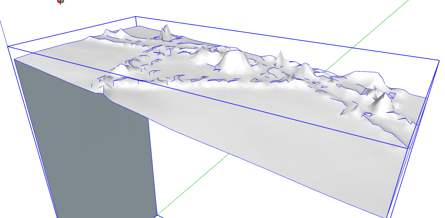
For completeness here is the smoothed DSM. Note the big mounds these are buildings. The smaller ones are trees. The terrain is a bit sharper too, showing there is some smoothing from DSM to DTM as well as the building and tree removal. Think the blue lines mean some edges need flipping?
It is the opposite. The terrain group is placed at the model origin if it and the group have the same coordinates.
Get Aerilius’ Attribute Inspector extension from the Extension Warehouse, so you can view and tweak the model’s "GeoReference" attribute dictionary.
I’m not sure as I never played with OSGB.
You might test. Would they be the x and y values when creating a UTM object ?
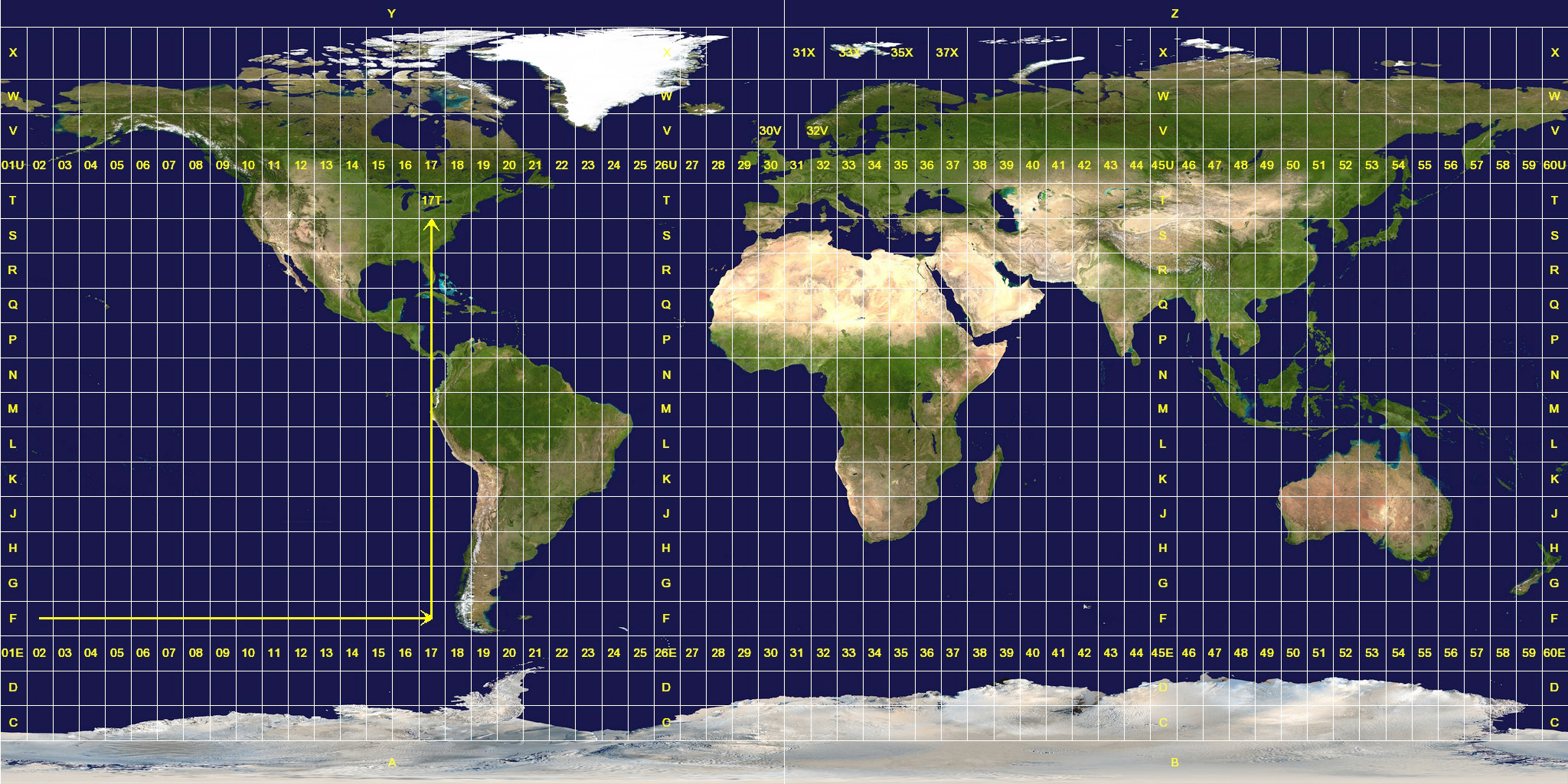
What values would you choose for zone number and letter ? (30U?)
Sorry mistake I meant “Currently SU apparently ignores these on import and places the origin at the SW corner of the terrain model.” Or more correctly “Currently SU apparently ignores these on import and places the SW corner of the terrain model at the SU origin 0,0,0”. I other words I think it probably is getting no sensbile georef data.from my workflow. I don’t have a building model in this particular file yet - it is in a separate file.
Was a bit tired and my words sometimes get scrambled when I am tired.
Good Idea I will!
I don’t think it is fully consistent with UTM - its a transverse mercator, but not as you know it Jim! GB uses UTM outside the GB but not within. The UTM zone for my location is 30 I think not sure about the letter, but from your diagram looks like U.
Essentially if I remember correctly there are two letters and two numbers per axis to define a 1km grid square. Then another 4 numbers per axis normally to define a location, though there can be more where more precision is needed.
It might interest you to know that I recently wrote and uploaded a Sketchup dll importer for .asc (as well as geo .tiff
files). I did this specifically for LIDAR map files available to me - which meant files from Norway and Sweden. The .asc file you refer to appears to have the same format used in Sweden. The dll importer also handles geolocation.
You can find the importer in the forums Extensions category. Please check the included documentation file.
I hope this helps you.