How to make floors and elevator?

image

I want to make a couple floors in this dome with an elevator in the middle.
51H_SOUTH_Simplified7.skp (5.7 MB)
Also is it a good idea to start by drawing the entire plan first instead of making the dome itself? Not sure where to start with architecture buildings in sketchup, I see a lot of people use plans first.

Hi,

I’d like to suggest a combination of things.

  1. Set up a Section Plane, so that you can see what’s going on inside of the dome.

  2. Use the Create Group From Slices option on a Horizontal Section Plane (right click menu), so you can easily generate your flooring cross sections at different elevation along the Z axis.

  3. Check out the option that’s available to Reset the Global Axes (Axes Tool), to each of the new floor elevations you want. This raise the ground plane to your new floor level and SU keeps all of it’s inferencing and snap functions in place albeit at the higher Z-axis plane. {You can always bypass this and just MOVE floor sections into position, if you find that easier}

  4. Paint the Dome with a nice transparent material for better visibility inside.

I usually start with the Floor Plan, and like that approach very much. In this case I wouldn’t hesitate to work directly from results generated with Elevation Slices from the Section Plane tool. Using a combination of possible approaches.

  1. by Shifting each floor OUT of the building (with a set distance) via the Move tool… So that everything is easily reversed to get back to original position. {e.g. 100 feet OUT and 100.1 feet back IN (adding in that extra .1’ for that perfect alignment)}

  2. Make a Component of the Floor… Keep Everything in Place… And Edit an Instant (copy) of the component in open space. All component edits get reflected in all component instances, so it’s a nice feature to take advantage of.

  3. There are also view settings you can adjust, which allow you to hide sections of the model… or for that matter… Turn off Layer Visibility as needed.


For the Elevator part. You can take advantage of the consistency of the elevator shaft between the floors, and use it as your primary alignment control.

(*) If I had originally drawn in, and extruded an elevator shaft up through the top of the dome… the section slices I pulled from the Section tool would have also captured those contours too. And that would have been a fantastic common point to reference–in a building with constant changes happening in the exterior walls.

I’m a big fan of drawing in alignment aids (and/or transparent reference planes), so that I can keep things lock into position. It’s of course most useful for things that go past a certain level of complexity… and unnecessary for basic rectangular shapes. But I still do it quite often even for the simple stuff as it allows for quick visual checks without pulling measurements.

Anyhow, In this case I would have made something similar to an elevator shaft as my so called alignment aid… and it’s only function would have been to keep me on track.

You have a better purpose and use of such things.

hi jim, thanks for your thorough response. i’m not able to cut a section plane into the dome without moving the dome itself:
image
any advice for this?

It sounds like the section plane you made, is stuck on the Ground Plane Level.

If you select the Section Plane (it will turn blue) you can then use the Move tool to raise it up along the Z-aixs.

If this doesn’t work, and you’d like share the file with me (which of course I’d be happy to look at) please save it for SU version 2018 and I’ll be able to open it with no issues.

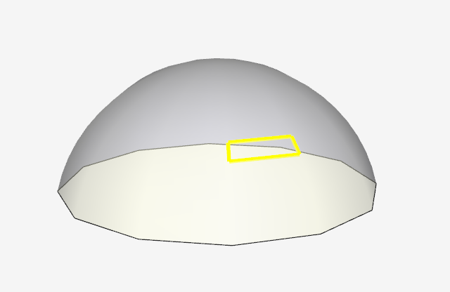
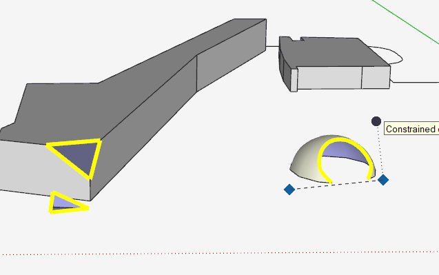
A Brand New Section Plane will be tricky to orient over a Dome… since SU is going to want to align it to one of the domes faces as soon as you start to hover over that.

Any other place you go in ‘Open Space’ is going to default to the Ground Plane Setting… which is based on where you have your World Axes set at the time.

An alternative to using the Move tool to adjust the Section Plane could be to change the Axes Location instead… and that will prompt SU to treat some other elevation as the New Ground Plane relative to the old one as it were.

Just to be clear here… When I say Axes, or Axis… I’m referring to one of the major 3D direction lines.

Individually they are:

Red Line = X Axis
Green Line = Y Axis
Blue Line = Z Axis

…and ALL 3 Collectively Create the World Axes [X,Y,Z] coordinate points.

… and the point where these 3 axes come together is called the Origin Point. [x=0, y=0, z=0]


A Nice Experiment To Try:

  • Hover your cursor over one of the main Axis lines… and Right Click on it.
  • Then Choose Move.

You should see a dialog box pop up… where you can enter in coordinate values for the new placement of your Axes Origin.

  • You don’t have to enter in a value to every field if you’re only interested in shifting your origin point in one direction.

  • Right Click on one of the axis lines again and choose RESET when you want to get back to the default positions that SU always starts out with.

{ Amazingly enough this so called default position is pretty interesting too… and there’s a special word for it, which I don’t remember at the moment. But it has a close relation with some universal coordinate system associated with Google Earth. }

Click in sequence on the Scenes tabs of this su file for ideas.

Dome with elevator.skp (237.1 KB)

This just a quick idea. The dome wall should have some thickness as well as the elevator shaft. I gave thickness only to the floors.

More ideas in this one.

Dome with floors and elevator shaft.skp (1.5 MB)

Is there a way to only have the section plane affect the dome? It’s affecting my other geometry. And I’m not sure why I’m not able to draw a rectangle properly under the dome.

image
51H_SOUTH_Simplified9.skp (5.7 MB)

And Jean, how did you group the two sides of your dome? Are you able to send a GIF?

Make the dome a group. Edit the group and then create the section cut. (Or cut and “paste in place” the section plane you already have “inside” the dome group, by editing it)

Make the Dome it’s own group (if it’s not already)… then Go into edit mode for the dome group, and create the section plane within that.

You could also use a Cut and Paste approach… where an existing section plane is cut from to larger model, and paste into any of the other object groups.

Sorry for repeating your idea here @pbacot, I guess I was starting to write my comments as you were posting yours up.

I think you’re fighting the SketchUp Inferencing System here. If you get too close to the dome, SU is going want to be helpful and start aligning your current tool selection (be it a rectangle, section plane, whatever) to one of the faces (i.e. /facets) that make up the dome’s surface.

To illustrate this better… try the following:

  • Turn ON the View Hidden Objects setting. so you see the underlying facets of the domes structure.

  • Take the Selection Tool and move around,… hovering over the dome’s surface area.

  • Compare that to what happens to the orientation when you hover over the open ground plane, or over one of the surfaces a more simple object like a box.

Somewhere in here, the solution will have to be that you work around and outside of SU’s inferencing system… and create the section plane in an open area of the model (which will result in an alignment with the ground plane (x,y, aligned plane).

OR, make an alignment jig… Create a box, make sure to Group it… and move it right next to the Dome. Use the surfaces on this box to better align (and constrain) the section plane tool in the manner you want to use it in.

You’ll just have to keep trying, I’m afraid. This is part of the reason I was talking about shifting things ‘In and Out’ of the dome space… so that you can work on stuff without SU creating inferences, and attempting to lock your newly drawn geometry to the existing dome walls.

I used a top view to be able to select only one half of the dome. I then create a group from this half.

After that, I triple click the other half to select all of it. The other half, which is a separate group is not selected and thus remains independent. I now have two separate groups that I can manipulate individually. After selecting the outer skin of the dome and grouped it and then hiding it, I can now access the inner skin. I can select it, cut it, enter the context of the group containing the outer skin and do a Paste in place. This put the complete dome in one group. After that I repeat this procedure for the other half. It is faster to do that than to write this text.

Another possibility is to hide both or any one of these groups to access the inside more easily.

Another possibility is to create the dome then move it completely up or aside, keeping only the floor slab to add whatever structure you need. Then, once done, you bring the dome back to its normal position.

Still another possibility is using Tags, Once the dome is grouped, assign a Tag to it and then hide the tag. I would suggest creating one group for the floor and another for the dome. Once the dome is hidden, you have access. A simple click on the dome Tag visibility control allows you to turn it on or off at will. You can even assign a Tag to the inside structures. That way, you have complete control on everything.