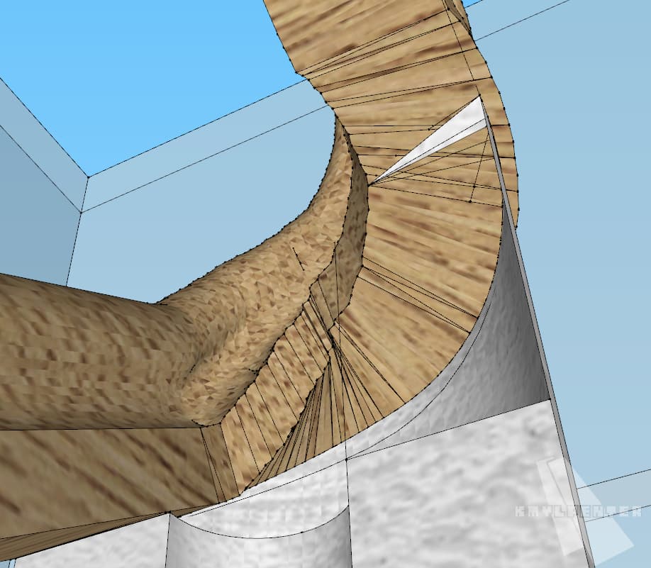
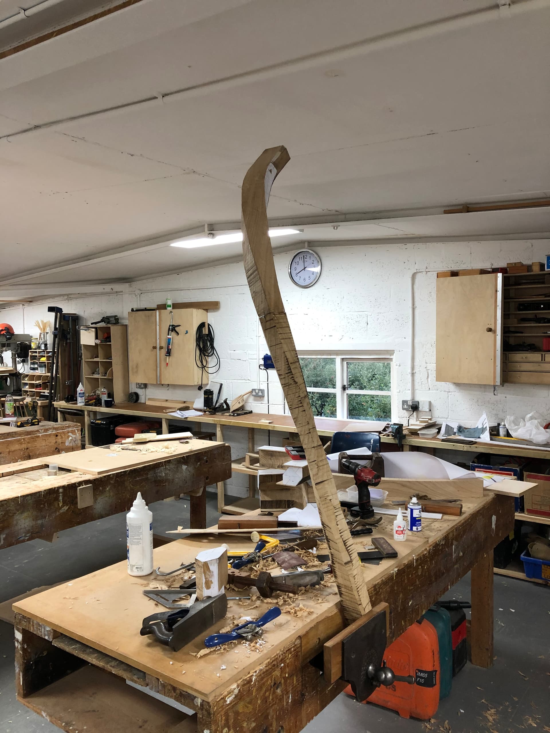
As you can see Im close to what I need for visual aspect of presentation but it is not enough as if we look closely - the curve is very uneven, on the internal side is super jaggy and looks bad:
The curve was created by using “Tax Engineering” plugin which out of three got me the best results. I tried Profile Builder, Follow me tool and Tax Engineering.
How can I draw it so everything is drawn smoothly? Is it possible to create that curve in sections - say 20-30 parts I could then measure and get cut by the carpenter to create entire curve?
However can happen that also miss creating the faces. Here are when you can use the Dave method.
Create a component, copy it to make other instance, scale up the new instance - by 100-1000- then make extrusion there. You can delete the “big” instance afterwards.
I used Curviloft to bridge between two push-pulled shapes. Upright Extruder distorts the profile - IMO the railing should have a constant cross section throughout
I’m curious about how this rail would be made in reality. Presumably from wood. Will it be laminate bent? Steam bent? made of small segments? How will it be shaped? Before bending or after bending? If after, what is the tooling? CNC router? I ask because I think that should inform how you create the model.
I will be making it myself from oak. I don’t have access to the CNC router that would make it so Im thinking of using small segments I could cut out of a straight profile with a bit bigger dimensions, then glue together and sand to get smooth result.
That is why I asked of drawing it in segments so I can measure what kind of pieces and on which angles Id need to cut the segments. Most of the time following the rule: “if you can draw it exactly as you intend to make it, you can make it”
You guys made it look so smooth now Im trying to figure out how to make my bazier curve perfect before trying out the profiling on it lol.
I’m not trying to talk you out of this but I believe you’ll find the profile will change fairly dramatically from the straight to the curved section and you’ll have a lot of sanding and shaping to do to make it all fair.
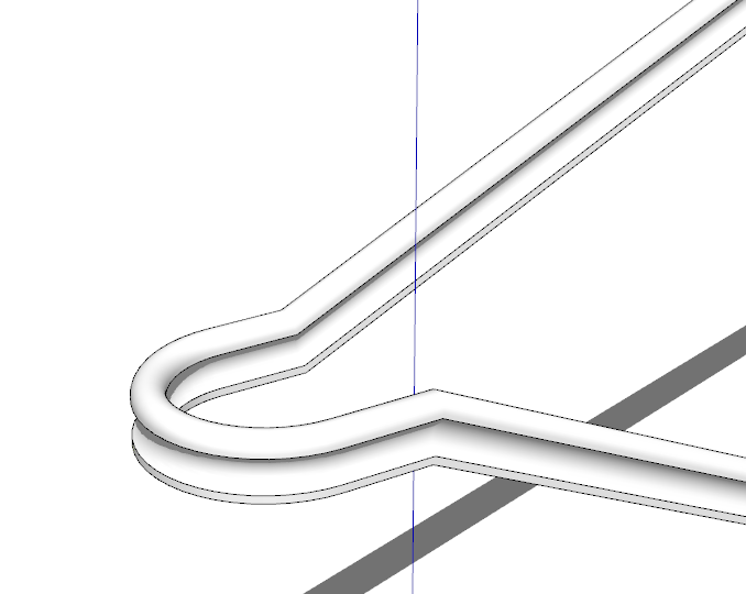
Have you considered making it more like I show here? It would be much easier to make and take less time.
You’re not wrong there - the problem lays in dimensional limitations. I can’t go with the curve any further because it lowers the amount of space between the column with curved rail and the wall. I need to keep myself in the dimensions. There is quite a few ways of making that kind of column, at the other company I worked they just used a hammer and a chisel to make the curve which took about 3 days of work from start to an end.
Managed to get the result I wanted by using curviloft Funny - I actually had curviloft installed but use it so rarely that forgot I can use it to make the shape I need! Thanks guys!
@kmylpenter you might try changing the face view setting to Monochrome in order to hide the wood texture. Then (temporarily) select all the railing geometry (triple-click) and turn off soft and smooth via the Entity Info window. The result will be a good view of the actual faceted geometry. You can then assess whether you like the result or if there are abrupt transitions that could use more divisions. (You can Undo the changes of softness and smoothness.)
We find with any one off job doing it by hand is the only way to get a beautiful line - but it’s also far quicker than drawing the whole thing out in 3D (Though I often have to so the client knows what they’re getting)
First rule is that the handrail form should follow an approximation of the the nosing line beneath, at a height that falls between legal parameters. It’s best to measure this line to the centre of the rail section and it’s often called the falling line.
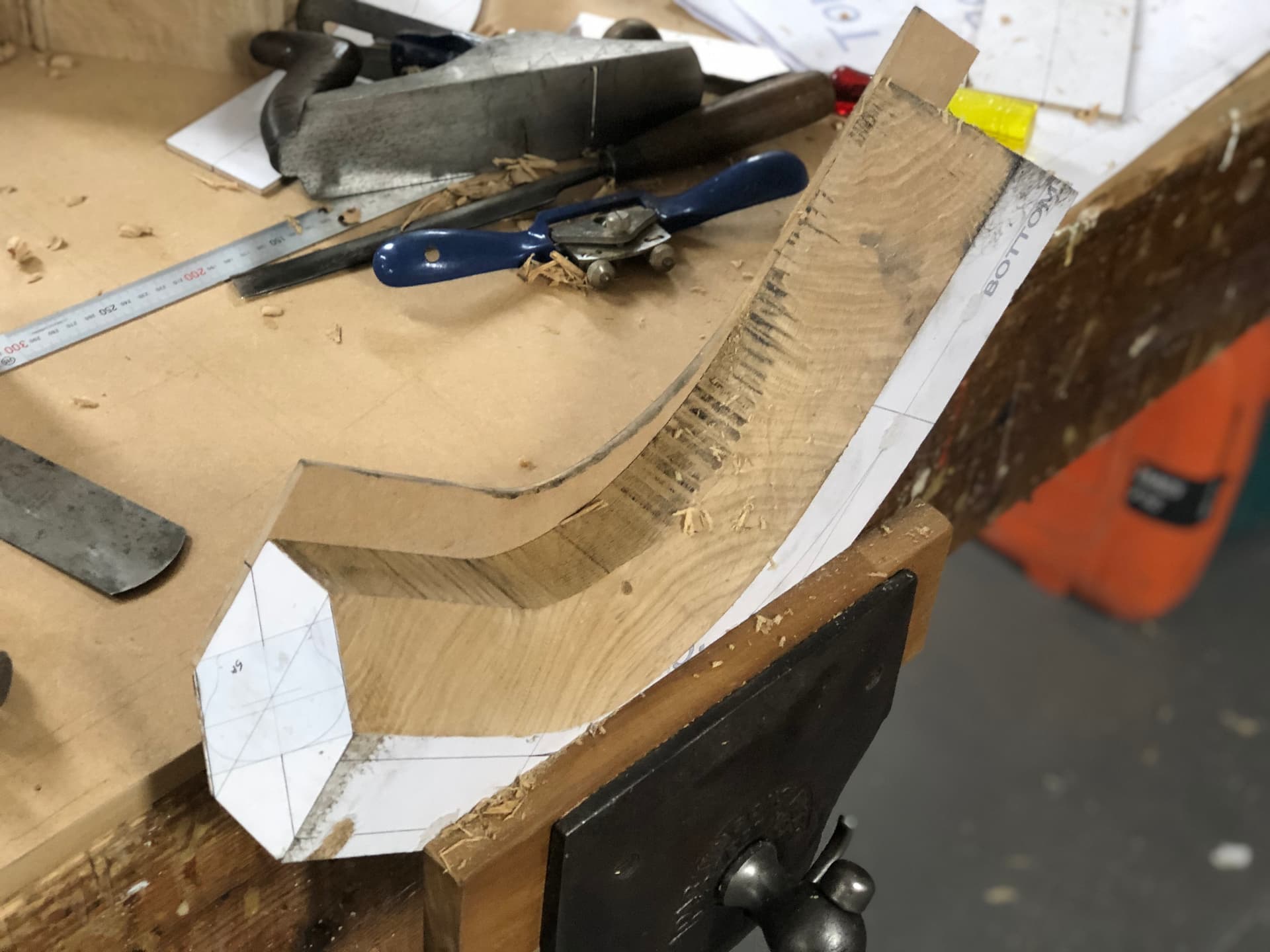
This job would require two ‘wreaths’ and probably at least one ‘easing’ to allow it to follow the line. These parts are first cut using a template called a ‘face mould’ from, believe it or not, a flat plank of wood. Then they are cut using a bandsaw or similar and by hand to create a rectangular or square section that is always perpendicular to the falling line which is at its centre, and whose top edge is always horizontal wherever it falls on the line. Thus as the falling line curves upward, downward or even pseudo-helically, the handrail can maintain its shape (except where the radius of the curve gets smaller than the width of the handrail).
The fact that the top line of the section is always horizontal means that the inner side of the wreath can be squared off of it, and subsequently the opposite edges can be gauged off of those.
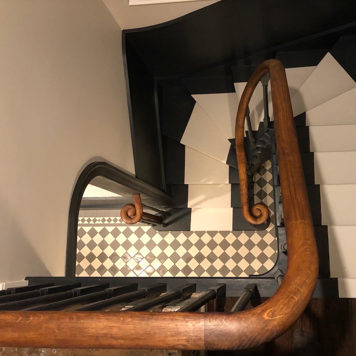
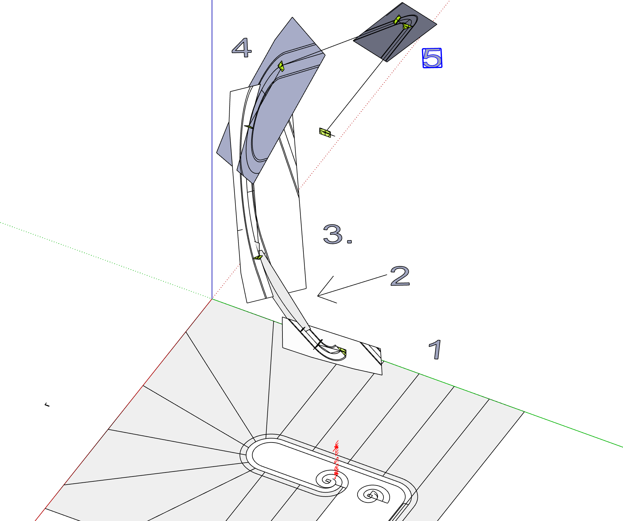
If you look at the wreaths on the images below you can see they have a squared straight section coming off tangentially at every end. These are called ‘shanks’ and are the means we use to create a perfectly square cut when joining two pieces of rail together; the shanks become waste, and you are left with a cut perpendicular to the falling line precisely at the tangent.
The process of creating the drawing in sketchup is a bit long winded compared to laying it out in 2D, but it does allow you to tweak the falling line for a beautiful curve, as well as getting a preview of the finished item. Also you can print everything out at 100% for templates. If anyone wants to know how the transfer from 3d to planks of wood is done, let me know - or read the books in the image below as you can work it out from the basic principles therein.
These are the face moulds from which the wreaths are cut from the plank. In your case they would look a bit like the shorter ones in the middle, but for this stair, the longest two are the moulds for the 180 degree sweep
The flat planes represent the timber planks and are the planes on which the face mould edges are projected from a plan of the handrail at ground level.
These are how I ensure the cut ends of the wreath are perpendicular to the falling line. The yellow rectangles represent the face of the cuts on both pieces to be joined.
As you’ve been already told eneroth upright extruder and curviloft are the tools I would use to do that. I thought profile builder would give you a better result
In my example the profile varies between circular and elliptical. It won’t generally be too noticeable for display purposes, but when you actually build it, you expect the profile to remain constant.