I have to say I am pretty proud of myself but I also think this is a great SketchUp testimonial!
Two months ago I decided to learn CAD. I wanted to 3D print and not other peoples creations. For the first two weekends I tried several CAD Packages. The first weekend I started with the Free ones- LibreCad and Blender. I think the brain hemorrhages are almost cleared up now because they seriously made my head hurt.
The Second weekend I tried the TurboCAD free trial because if I liked it the home version was $99. It was not bad and I got a grip on 2D pretty quick with only minor bleeding! When it was time to go 3D though it simply befuddled me and I could not generate a STL file.
The third weekend I tried SketchUp. I did the four tutorials and holy ■■■■ that was easy! I whipped right through the four ‘included’ tutorials – it was so totally intuitive! So I went on to more tutorials on Youtube. I have had to get help here on the forums a couple of times on some sticking points but the help here was so good, so fast and so friendly it was unreal! It’s more like your buddies helping you out.
So 6 weekends after touching SketchUp for the first time I sat down yesterday and did my first totally from scratch design!
I took most of Sunday putting this together (well all of Sunday less mowing the yard) but I think it says a lot about this product that a guy after a few weekends of You tube videos could pull this off in a single day…
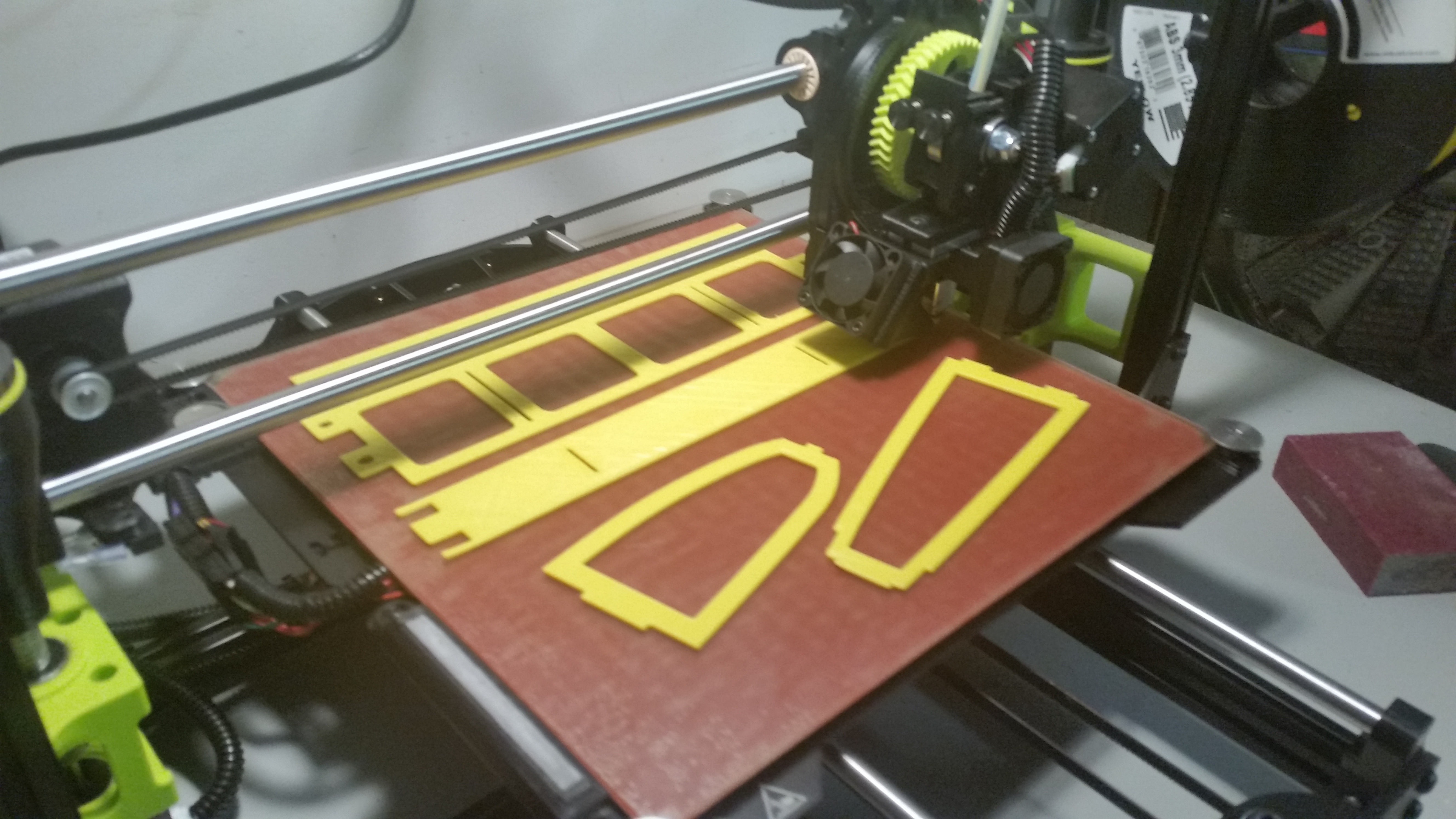
So my 3d Printer will print at max 10.8 inches by 10.8 inches. I want to build planes larger than that. So I designed 5 basic parts. The max length of any given piece is 10.5 inches.
The shot shows a completed assembly of 7 parts (had to print two sets of rib “rings”) So I now have a 10 inch section of wing (minus the control surfaces at the rear of course.)
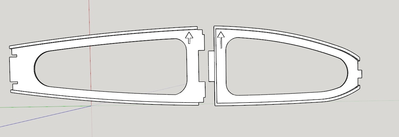
Now to the magic part… this shot shows you how the the 10 inch sections are modular. You can ‘snap-on’ 10 inch modules to make the wing span you want. This pic shows 3 modules for a 30 inch span wing.
Does your Mom get a copy of your 2D cad design, or are you giving here the finished 3d printout instead?
Technologies change, but traditions still hold that Mom’s need something to attach to their refridgerators… pictures of the grandkids typically take first place, but art work is of course a close second.
You are right! I am sure Mom will swell with pride when she sees the 2D flap track I created for my single slot fowler flaps that I could not get into 3D. I can hardly wait to see it stuck to the fridge!
Very nice design. I’m curious if this is only an exercise or do you intend to do something with it? Not sure how it would equate to practical use in an airplane design as the spars need to be quite strong and having seams is generally very undesirable. Also not sure how 3D printing (versus machining) would generate anything strong enough. But the design itself and your mastery of SU is impressive.
I am bored today! I work databases at a national retail outlet so I have to be here in case there are any problems with the website or store POS systems however hardly anyone else is here and so unless something does crash I have NOTHING to do.
So I will kill time giving you answer that is probably far too long. Still, I think you raise very good points and I would actually enjoy addressing them with and I have the time so…
LOL! To quote one of my favorite TV shows, “Failure is always an option!”
Well the trick in aircraft is not absolute strength but the strength to weight ratio. If you build a very light structure then a lot of absolute strength is not needed. Several tricks come into play there. 1) Stresses generally go around the edges of a structure so that is why the parts are basically just outlines. That results in a vast reduction in weight with a very small reduction in overall strength 2) Now add the flanges around the edges (making each part a virtual L-angle) and again you buy a lot of added strength for small amount of additional weight.
“Honey combing” - adding structure inside a nominally hollow part to keep the strength to weight ratio higher. The printer software does not do true octoganal “honeycombing” like on full size aircraft but the prictured crosshatching is something that is very easy to do with 3 printing. Well at least with the Cura software I am using it is very easy to do.
a spar does not live alone…there are three spars (leading edge, main and trailing edge. All combined into a virtual box by the ribs.
You lost me on the “seams”. Do you mean where individual parts join together? If so, I think I have that under control with 1) How the parts ‘notch’ together - note how the slot in the main spar is filled by the aft rib sliding into the spar slot from the rear - then the forward rib sliding into the combined notch of the spar and aft rib. Now the spar is now solid (except for the the radiused lightening holes) 2) Adhesives today are quite impressive. It is quite easy to have a bond stronger than the actual part. So put adhesive on those ribs before you slide them in and now 3 individual parts became one part
Well, we will see. Before I dove in I did some test prints with honeycombed PLA and I was very impressed with the strength to weight ratio, Again though, I think I have all the angels covered but “failure is always an option”
On a totally different note, the single biggest problem I am having with printing verses other methods is tolerances. e.g. I those ribs are drawn 3/32 thick as well as the slot in the spar however I widened the slot 1/64th to allow a little room. The ribs came out MUCH thicker and would not go into the slots- not even close!
I found I have to watch the slicing software and do the math 1) the slicer software wroks in millimeters and I am doing standard 2) as the initial layer height and additional layer height in the build up may not come out evenly (to the millimeter) and the software will round up. I expect machines to obey! When I say 3/32 I mean 3/32 and NOT “>= 3/32” ■■■■ it! Stupid software!
Thank you so very much! I really appreciate that! I really do! Yet I have soooo much more to learn!
Those spars look like they are about 5 inches high, which would make it a pretty big RC plane. And even so, you still have an engine, fuel and electronics.
Thats some very skilled modeling already, 2 thumbs up!
PS will those locks keep in place? They are just straight joints, i thought it would be better putting a small angle on them or a small cutout with a part sticking out on the part it needs to lock on to.
Oh! My apologies, I should have made that far more clear from the beginning that yes this is a radio control airplane!
I am shooting for a 60 inch wingspan. The main Spar is 2.5 inches tall. I would like an all up weight of 6 pounds. The drive train is 2 pounds then another 1/2 pound for the control system (servos). So I have 3.5 pounds to work with on structures. If I go a pound or even two over it will still fly fine but a weight of 6 pounds is the goal!
Friday night I finished printing one “module” and it weighed 5.2 ounces. That makes a 60 inch wing right at two pounds. Not too bad but not that good. If that was the all-up weight with control surfaces and servos I would be happy.
On the other hand it is extremely strong so I put all my parts on a diet reducing all thicknesses everywhere and got it down to 4.05 oz per ‘module’ So a 60 inch wing is now 1 1/2 pounds. I like that but it is still very strong so I trimmed some more weight last night. “Version 3” is on the printer now. Maybe I can get it down to 1 1/4 pounds?
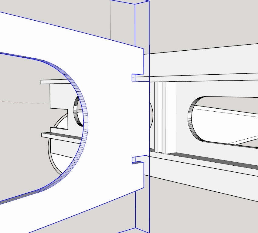
Now the two rib halves join inside the main spar. It is hard to see though. I tried a screen shot of with x-ray but there is too much going on there…Hopefully a picture is worth a 1,000 words.
In this shot I deliberately reversed the face the wrong way on the aft side of the forward rib. It is inside the flanged slot of the main spar. It is also circled in black. Then the aft rib slides forward into the main spar.
Then I totally redid the trailing edge this weekend making it stiffer and lighter with two raided (It’s almost a “pi beam”,
AR!) The center tab on the rib comes all the way through and flushes with the aft side of the Trailing edge.
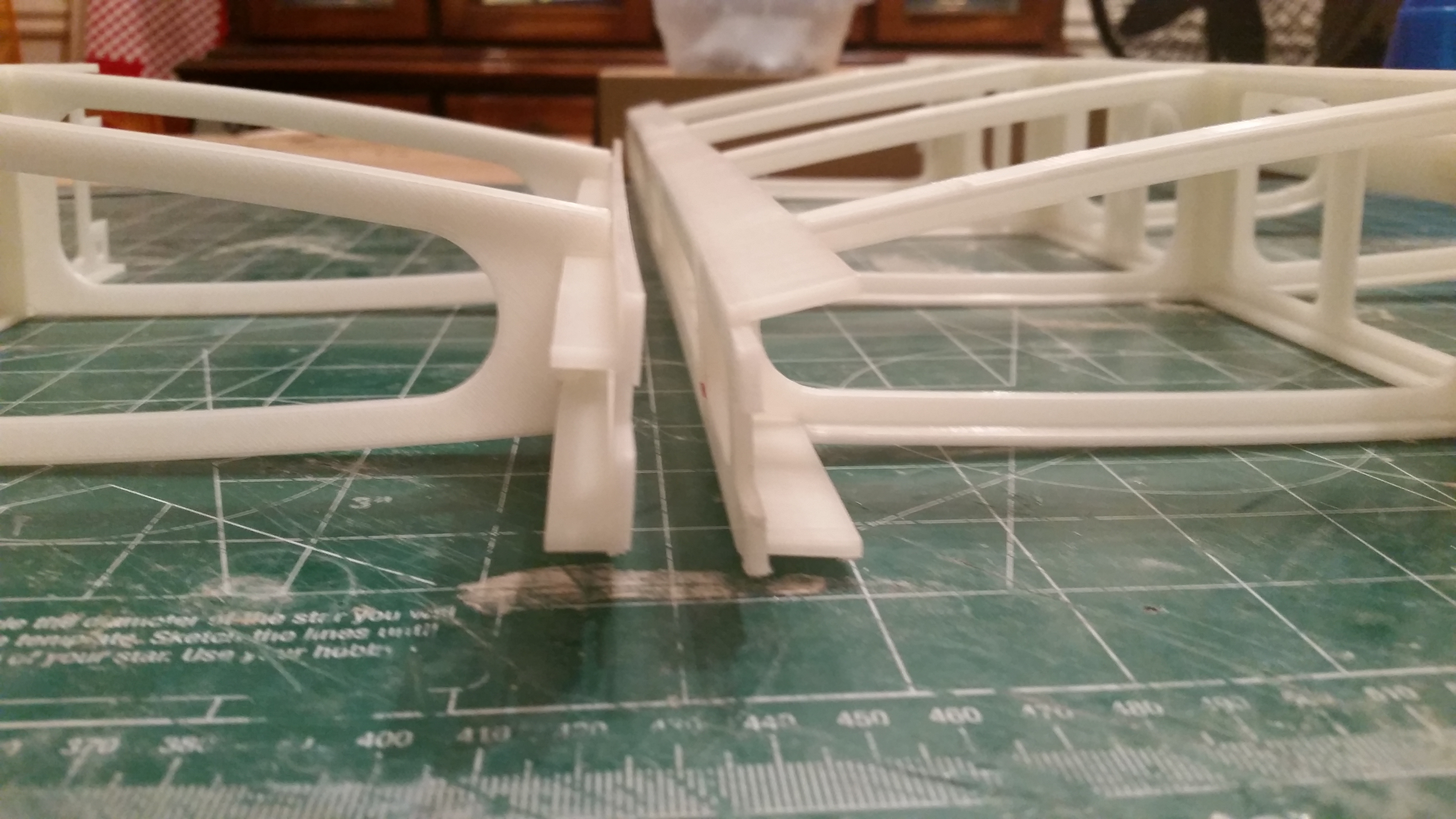
Here is a shot of two modules of Version 1 printed out and glued together with CA. It came out way too heavy but you could play foot ball with this thing! It is TUFF!
Here is a shot of Version 2 (left) next to Version 1. You can see how much bulk I took off of all the parts- particularly the two trailing edge’s are in the center of the picture. The ribs are the same size but they look much smaller- a classic optical illusion because I took so much material away from the piece. Not only is it lighter it prints faster!
Ok, so for my fellow 3D printers. As I wrote above I was having rounding problems in the slicer software during standard to metric conversions it seemed to round up so my parts were coming out larger than I wanted.
As I have been dealing with standard units for roughly 50 years I was very reluctant too this but I did; I switched to a metric template in SU and started using metric. My tolerances are FAR tighter now than they were with standard. When I say 2MM I get a 2.05 MM finished product.
Just as a bonus, in smaller sizes MM are so much easier to work with than fractions or oddball decimals. I started off with 3/32 or .0938 as my standard part thickness. 2, 3 or 2.5 mm is so much easier to work with! Now larger sizes I am still struggling with mentally- my formerly 10.5 inch parts are now 266.7 MM Can’t win them all I guess!
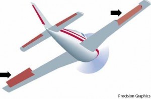
Well the holidays and side projects slowed me down but I have designed and printed my ailerons. For those of you not at all into airplanes you can see where the ailerons fit in to the picture…
First of all I have now learned to draw big! My ailerons are 10 inch by 6 inch but I drew at 10 times.
So using concepts new to me but old hat to everyone else (I am sure) I made components out of the huge parts and scaled down copies to print. Additionally, my large version is drawn “assembled” and the small parts are laid out for proper side down for STL generation. When I change the big part (component) my small print part changes too!
This was awesome and a HUGE time saver! I know, old news to everyone else but a HUGE new “discovery” to me!
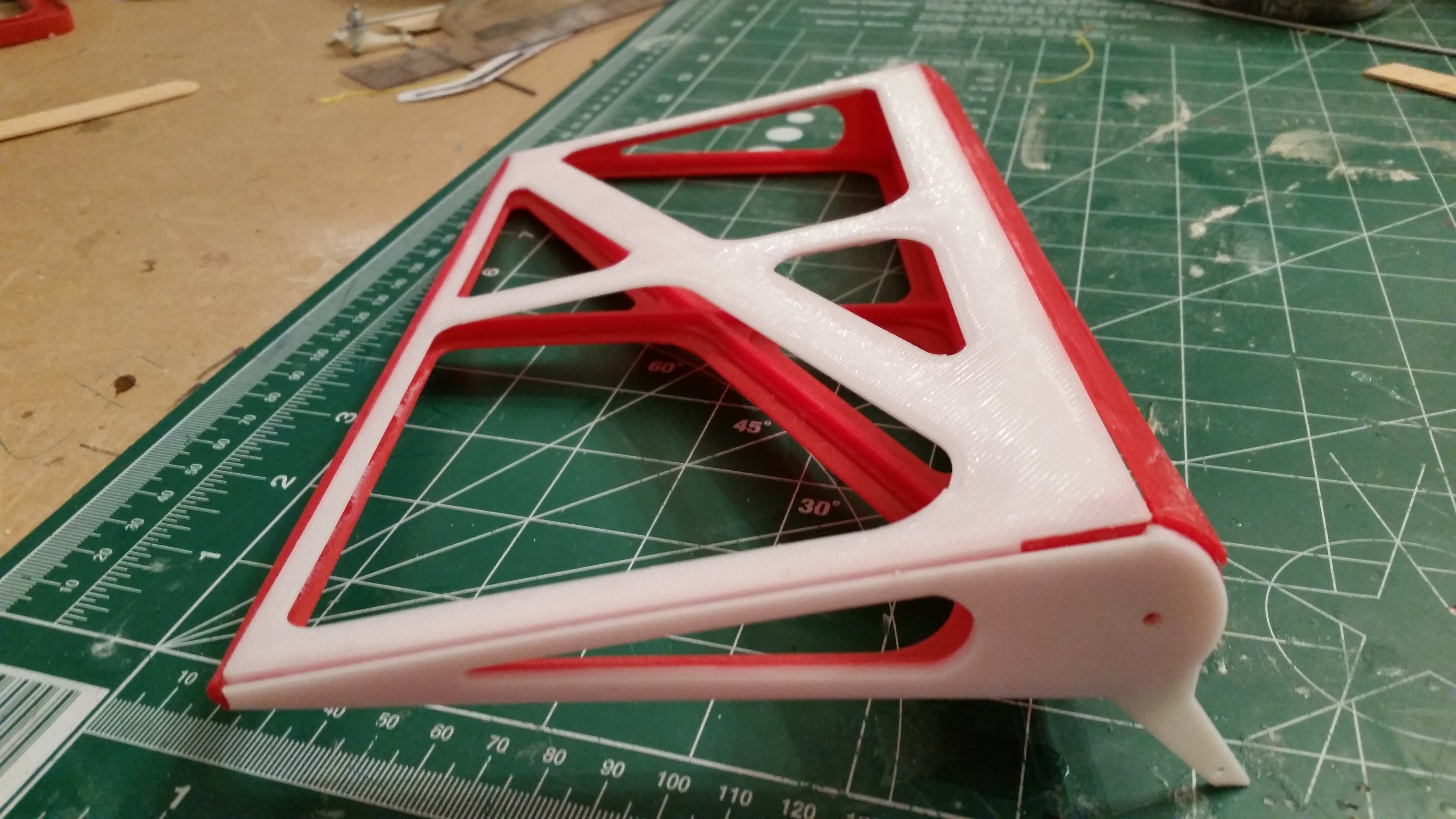
So in the contentious battle of strength to weight ratio I got all crazy in designing the aileron skins which would be significant portion of the strength while having as little weight there as possible. I think I over did but my OCD really loves all the curves!
I designed this to be a little ‘androgynous’- So here you can see I have EITHER and left and right set OR I can splice the left and right parts and make a single 20 X 6 inch aileron. So components to the rescue again! The parts on the left are already scaled down copies of components then the ones on the right are scale -1 mirror images of the ones on the left! So when I change the base component both right and left parts change at the same time! So cool!
I will try to ‘skin’ this with Fredo’s Curviloft but it that fails I will go with hobby industry standard of covering film (Ultracote in this case) for 'skin"
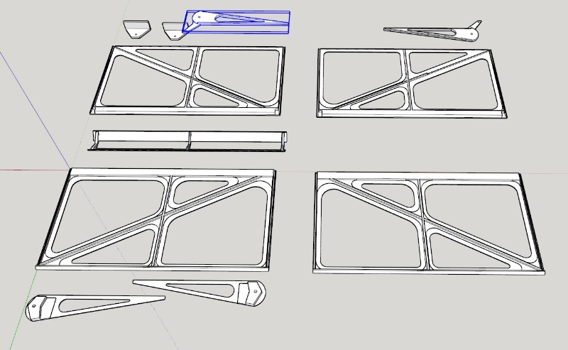
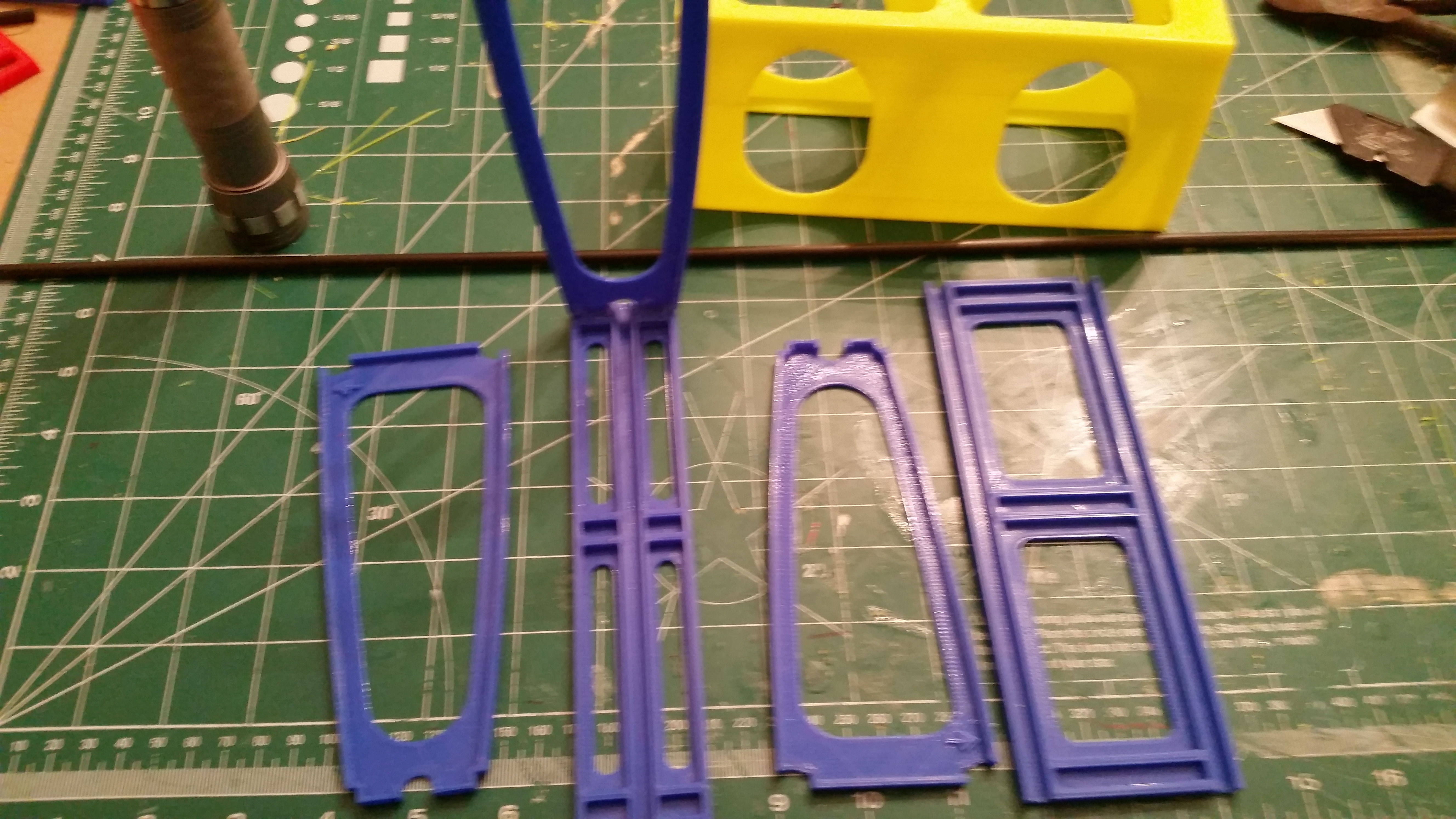
Ok. completed the Gen 2 wing design. Due to dimensional tolerance issues with 3D printing I greatly simplified the overall intricacy of the parts wherever they mate including just getting rid of the whole tongue and slot concept completely. To make up for lost strength I incorporated 5 MM carbon fiber rods. I also learned I have to use 1 mm tolerance if you want parts to fit with minimal sanding/trimming. (I started with .2mm tolerances)
Here is every part needed to make the entire wing now. The redesigned original 5 parts are on the right side.
That included the addition of my center wing section. Once again, here on the forums, I learned a new trick. I learned early on that push/pull does not work on airfoil shaped surfaces. However, reading other posts and again learning from @DaveR@Box and @TheOnlyAaron I learned the totally cool trick of intersecting parts and then I could put lightening holes in my airfoil! That cut the weight in half! Thanks guys!
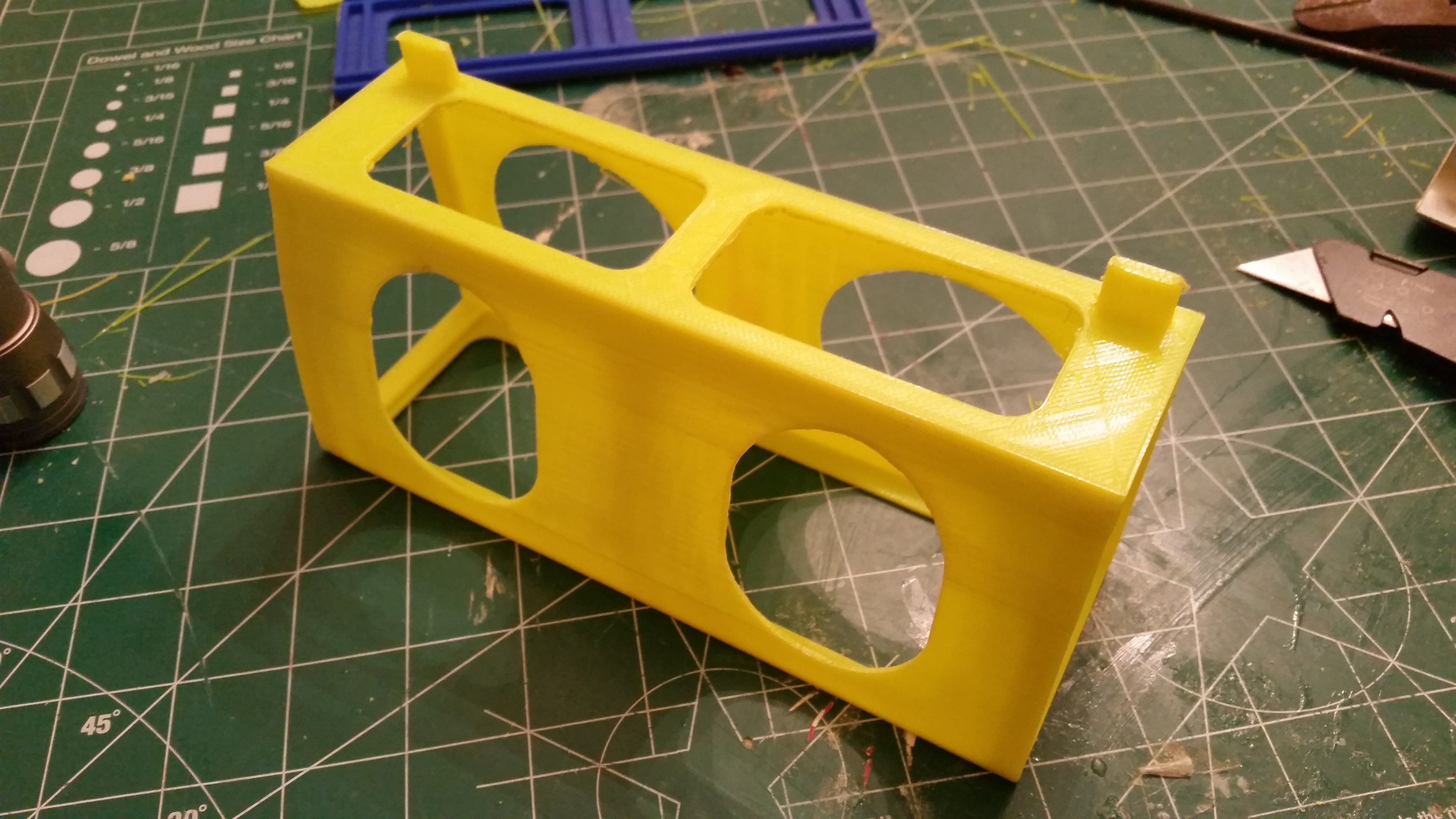
This part is belongs in the 3d printing thread but I take some degree of pride that I managed to print a “roof” with holes in it! there is not a single solid surface on that print! (I only cheated a little)