5" 38 Twin Turret Cutaway

I’m giving Ryan a choice of how to display the innards of the gun house. My first approach would be a cutaway, but while not to difficult to execute, it doesn’t show all that much unless you turn it into Swiss Cheese. Ryan just texted me. It will be the cutaway version which follows the theme of the 16" project.

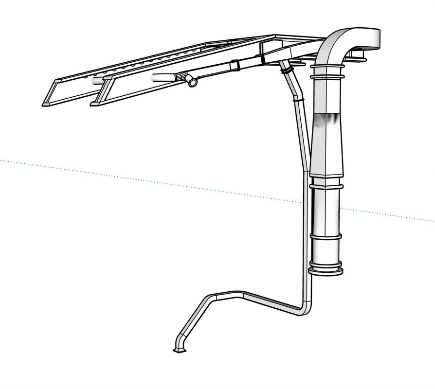
The second approach could mimic yesterday’s photo showing the entire armored casing in the air above the open gun house. This would show almost everything, but would have to be suspended above and it would raise the enclosure height. I could use acrylic rods to support. Lighting would require some visible cabling. In order to raise the casing, the guns need to be elevated, as they are in the photo.

The last is the most elegant and also the most challenging: making the forward parts of the gun house out of clear acrylic. I would leave the curved wall as it is. While I have clear resin, optically it wouldn’t be very good and not any value. Acrylic is very clear and shows no distortion. Gluing it together so it really clean is the first challenge. The second is cutting out the small parts with true and square edges.

So I’m also asking all of you. Which do you prefer?

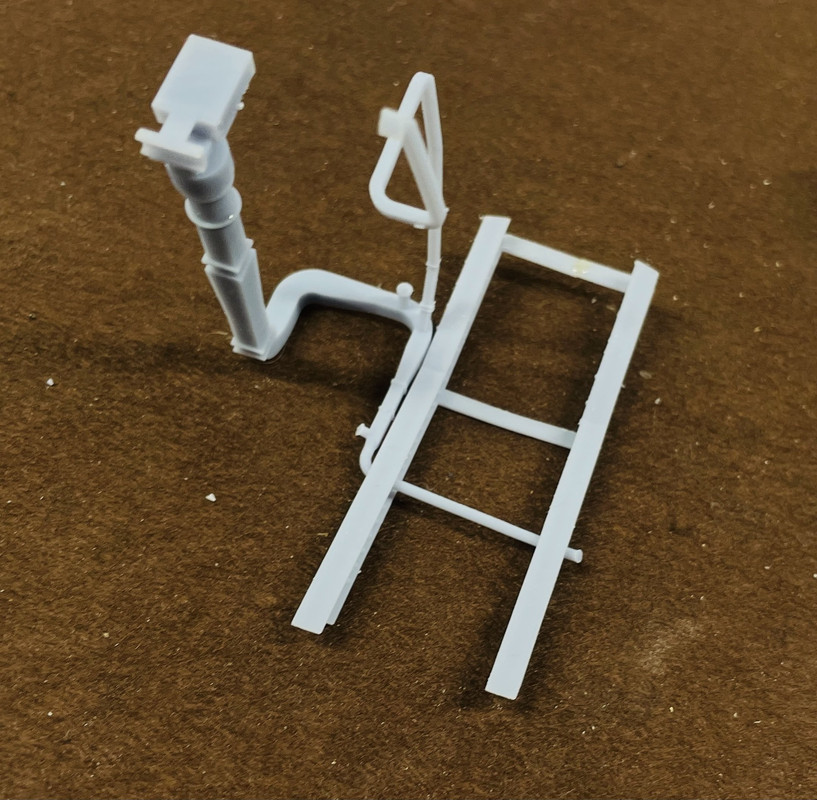
I finished cutting out all the casing parts and trued up all the edges. I cut the telescope holes in the right and left sides, the ofc’s hatch opening, and the remaining access hatch opening. I clamped both angled face pieces together so I could finish shape the gun slots so they aligned perfectly.

To cut the telescope holes, I drilled a series of small holes through the drawing, and then used a larger drill to make nice rounded corners.

Here’s all the finished parts ready to be assembled.

s

Since I don’t know which version Ryan will pick, I did some future planning… While all the casing parts were in the flat, and they’re all accurate, I clamped them to a nice piece of 0.080" acrylic that I had laying around and traced all these parts so I’m ready to cut them out if we go that way. If fact, regardless of Ryan’s choice I may cut out all those parts and see how well I can finish them. Having it clear would be pretty neat. You can barely see the scribed lines, but they’re there. Now that I know Ryan’s choice, I’m going to try and construct this version anyway since I’ve kind of wrecked that part of the acrylic with my scribed layout lines.

I also went at the back of the curved wall and removed that lump. I used a cutting disk to remove most of the stock and then my micro-power sander to finish. I may add some filler to hide all the tool marks.

With the acrylic in the wings, I can continue to construct the regular casing. I won’t do the cutaway until after it’s built if i go that route, so I won’t be getting too far out over my skis.

My new LCD panel arrives today and I’ve already stripped the old one out of the machine in anticipation. I hope it comes with a new under class plate since I cracked it a bit getting it out of it’s depression. It too is held with adhesive stirps. Should be running next week. It has to be running next week. It’s on the critical path of two major projects.

Y’all have a nice weekend!

3 Likes

So, I’m guessing that Ryan liked the acrylic. It sounds like you like it too. I agree that whatever shows the most would be the best. I think you can do it. Good luck.

Nope. He liked the cutaway of the regular plastic since it emulates the look of the 16” model. It’s the easiest for me to do. I don’t want to open it up too much. There are nice girders in the ceiling that I want to maintain.

It’s been a while since I updated this post. I have been working on five projects at once; three of which are commission. This technically is a commission although I’m not charging anything for it. When I last left you, I had to rebuild my 3D printer. I installed a new LCD panel which went well although more trouble than I thought. It’s printing well now. I also found out recently, when testing my exposure setting with a new test article (Starship from 3DRS) that I was under-exposing my resin by 20% since I got this machine more than a year and a half ago. When I initially calibrated it I used a simple flat calibration piece and derived 2.5s per layer. With this new part, 2.5s didn’t work. I printed a test from 2.1s to 3.1s by twos. 3.1 was it! It explained why I was getting such warpage and support breakage. When exposure is too short, the resin doesn’t have enough cure time to develop structural integrity. The warpage is due to the amount of hardening that still needed to take place in post-curing. And the support breakage (a resultant delamination) was due to the resin being too weak to perform.

During all this, I was designing the ventilation system that goes into the gun house. It’s a tricky design since the drawing is unscaled and undimensioned.

I had designed the overhead I-beams (wrong, I might add) and then Ryan came through with a passal of images showing the entire ceiling of the gun house (also good views of the ready service room and magazine). I have four beams. There are only two. I also had lateral beams. There are none. I also needed to know how the cross vent passed around the I-beams. They don’t pass, they go through. Makes sense since head room is so limited. I drew the assembly and decided to print it all in one go, I-beams included to ensure it all lines up. I did’t design the blower system yet as that will be a separate part to glue in.

This was the image that told me what’s what.

I placed my assembly into the gun house drawing and kept moving parts of it around until the ducting cleared the guns and nestled into the I-beam.

I scaled it .021, exported as an .STL file and loaded it into the slicer. My first setup used a 100% raft coverage area. The Tall aspect on that little raft started failing about 1/3 through the print. I could see it detaching from the build plate since the plate has risen enough to be clear of the resin level in the vat. I stopped the print knowing it would just be a waste of resin.

I redesigned the arrangement with a more substantial raft. I am having no problem with build plate adhesion and blamed the strange setup for the lost of attachment.

This will off the machine later tonight so I won’t know if it’s good until tomorrow. Once the ventilation is squared away, I’m going to dig into all the electro-hydraulics in the gun house, and then onto the ready reserve room below. With exposure change, I’m much more confident about fine details and small piping rendering nicely. I may reprint some of the more dubious parts I’ve produced so far. I haven’t glued or painted anything yet so it’s just time and some resin.

4 Likes

Looking great ! Boy it must have got hot in there……

This is always the mostist funnist part when you’re working sans plans and blueprints. A VFX artist friend at a big animation studio often mocks the time it takes me to draw stuff, saying he could get an intern to complete it in a morning. True, I reply. But the result would be all wrong and look like garbage. :grin:

4 Likes

That’s true. Designing something that actually has to fit together and even worse, work, is the real challenge. When I taught metal shop many, many moons ago, kids would bring me some clung that they built and when I commented that it didn’t look like the plans, their answer was, “That’s the way I wanted it to look!” It wasn’t until we did a group project to build a working model steam engine, that the lights went on. They realized that if the specs weren’t met, the thing wouldn’t work. It was wonderful!

It was horrendously hot in the working spaces on those ships. The only air conditioned spaces during WW2 was the powder magazines (for obvious reasons). I simply can’t imagine what it would be like buttoned up in those armored structures in the South Pacific in Summer. They were air conditioned during later refits.

The print was successful and is still on the machine. Now I have to figure out how to assemble it. Part of the vent goes down to the handling room below.

5 Likes

That’s it entirely. For instance, there are a bunch of Abrams tank models available online that look so much nicer than my own. The artistry is obvious. One of them is complete with welds that look like actual welds! I have no idea how they do it.

The problem with these gorgeous models is none of them are correct. So far as accuracy goes, the least worst are “kind of” accurate, with the rest somewhere between “Uh, what?” and “Lol, are you kidding me?” – but they do look nice, and were likely completed a lot faster than mine!

1 Like

This one’s going to be somewhere between, “Really!?” to “Boy! That’s really amazing!” Hopefully more to the latter than the former.

Just when I thought I had it nailed down last night, I tried the drawing again in the turret, and this time viewed it from a different angle and found this…

I had to re-configure the ducting that entered the handling space below. It had to clear the gun, all framing girders and enter the space through the center ring. What I came up with worked, but I have no idea how accurate it is. Ryan’s pics don’t show this particular duct. I also took the time to draw the blower system and set it up to print as a single assembly. The new printer settings are working perfectly and I had a lot of confidence that all of the parts would render.

The print is done and mostly cleaned up. I may still have some trouble with the upper outlet pipe. I may be interfering with the right gun’s curved shield space. Everything printed perfectly, nothing warped or broken and all the bolt heads showed up.

Now I just have to figure how to shoehorn this into the model during the build…

3 Likes

It’s amazing how often those absolutely rock-solid perfect 2D drawings fall apart when rendered in 3D! :grin:

This is looking great!

If you are still drawing various components in separate SKP models and only occasionally bringing them together into a single SketchUp session for fit-checks, I suggest you reconsider that approach. Catching collisions like that is much easier when you create the geometry in-place within the master SKP model. I realize that at some level of complexity (millions of edges and faces, depending on your compute resources) a single SKP model can become quite cumbersome. In such cases, using separate SKP models can be desirable but it runs the risks of collisions, mis-alignments, etc.

2 Likes

Yeah… getting stuff to fit into our 3D world does add a bit of excitement. As too drawing it all on the master. I try to do this until it gets so sluggish that I give up and doing it on a separate file. I had to do that in today’s case. That’s with making as much invisible as I feel necessary with tagging.

Work progresses…

I designed the Training Gear hydraulic plant. This sits down between the girders on the gun house’s right side behind the Trainer’s seat and regulator. Luckily this one is drawn in profile in one of the cross-section images I found so I could get the profiles down. I’ve scaled these drawings so they are representing correct lateral dimensions.

There are two output shafts that extend out of the end and I probably will make these out of correctly sized wire. It was gratified after finishing the drawing that it fit perfectly in the space it was supposed to. I have an add-on that facilitates making those neat curved edges. Also, SU is pretty easy to draw complicated pipe runs once you know what you’re doing with connecting lines and adding curves to them.

Here it is dropped into position.

Next up will be to design this units hydraulic counterpart, the Elevation Gear Hydraulic Plant.

As in the big gun’s turret, all the systems are driven by hydraulic motors with the pressure generated in a remote motor/pump setup. In the case of the big gun, the motor/pump (A-end) was physically remote from the hydraulic motor (B-end), but in the case of this smaller turret complex, the motor/pump was directly in line with it’s b-end hydraulic motor.

With my newly refined printer setup, I have no doubt that all that delicate piping will render. It should look pretty good.

5 Likes

I updated my SU 2023 and now V-ray is not booting up. Anyone have any thoughts?

I saw on another post that V-ray doesn’t transport over to the upgrade and I will do it manually. Hope it works.

The Elevation Pump/Motor Hydraulic System shares the same motor/gear box/reservoir with the Training System. The output end is completely different and the units are mirror-images of each other. But having successfully crafted the one, drawing the other went quickly. Both just came off the printer and, with the new exposure settings, the detail is exceptional and all the piping is intact and tough. I’m very happy with these results and it tells me that anything I can draw for this project with print as I want it.

I’m now wrestling with the human interface portion of these systems, the pointer’s and trainer’s regulators. These, like the rest of this job, are not easy to visualize or draw. All the pictures I have are persepective images and therefore, I can draw directly on them. There are very few surfaces that are parallel to the SketchUp axes, and many of the corners and junctions are rounded/curved. None of this makes it an easy SU drawing project, but I will persist. Ryan Syzmanski is enjoying seeing all these components separated from the complexity of the insides of the turret.

I’ll post the finished parts tomorrow.

4 Likes

Gotta envy the lucky folk who get to model from actual dimensions. Talk about luxury.

I apologize to @mmarcovitch for a brief digression, but I want to reply to @Saul 's comment. Firstly, there must be some published accurate dimensions of the M1 Abrams tank (which is Saul’s chosen subject). Use those known dimensions with photographic coverage to estimate other dimensions. Such estimates are of course not as good as direct measurement, but they might be your best option. I have estimated many many thousands of dimensions for my subject in this manner. Even though I have about 1500 direct measurements of various features (see below), it is never enough. I have personally captured about 3500 high-resolution photographs of my subject to use in making such estimations. The dimensions and photographs that I have spent considerable effort to acquire are published for free on the web, by the way. (There are rare exceptions; the owners of some artifacts asked that I not publish my research from their material.)

Here is a video I created 8 years ago describing the process I use:

Secondly, I don’t consider having dimensions of my chosen subject to be luxury. I have spent thousands of dollars traveling across country, purchasing precision measuring tools, and arranging time with museums etc. to acquire my own measurements of my chosen subject. I suppose you could say that I have the luxury of being in a financial position to invest that money (and time) into research on what for me is a serious hobby. For what it’s worth, here is an example that I used to capture and record some dimensions of one of my subject’s components (the numbers in red circles are generally inch dimensions):

4 Likes

You put me to shame :face_with_open_eyes_and_hand_over_mouth:. I’m much lazier than you and don’t go to your lengths to capture dimensional fidelity. I kid… Gettimg life measurements from a16" turret (or 5" for that matter) are beyond my reach physically, accessibility-wise, financially and time-wise, so I have depend on a lot of educated (or dum-luck) guesses. But, as McCoy said to Spock in Star Trek III, “Your guesses are better than most people’s sure-thing.” I tell that to my son all the time since he is a freaking genius and terrific doctor. When he guesses I tend to listen.

That said, with my current project, absolute mechanical accuracy is unwarranted and impossible for me to attain. (That sounds like a rationalization. According to Woody Allen in ((I think) Annie Hall, “You can live a day without sex, but you can’t live a day without a rationalization.”) It just has to look right enough to convey the information intended and that all the parts fit inside their respective spaces in a realistic way. I do scale every drawing if possible when I know at least one measure upon which to set the scale. I love SU’s capability to scale an entire group/drawing with one single measure.

2 Likes

Yup, that’s been my life for a while now!

My comment was aimed more at architects and the like.

@mmarcovitch, do you have hands-on access to your subject? Or to people who do? That would be wonderful. Imagine being able to whip out a micrometer and calipers, or a tape measure and protractor and actually measure the thing you’re modeling! I bet that’s what heaven is like.

There are no such data officially available, since the Abrams is still classified an active first tier weapon system. However, there are some semi-official data floating around in the form of a very rough copy of a copy of a copy of a copy of… 2D drawings from an ancient Army manual. These can be found at kitset modeling forums and similar. The problem with these data is they pertain to the XM-1 prototype and some dimensions haven’t been valid since the late 1970s. Things change. Another problem is that they were intended for the instruction of Armor Branch recruits and so are not particularly precise: Inches to two decimal places, rather than the metric to three decimal places standard of the US military. And then there’s the unfortunate fact some of the dimensions are flat wrong. Not outdated. Actual errors. I found three, but I can’t be sure there aren’t others.

Other sources include a magnificent set of 2D drawings by a non-official third party. These look wonderful – it’s great work – but the numbers are questionable for several reasons. One, there’s no way to know if they are hands on measurements and, if so, there’s no way to tell how accurately they were measured. Two, the drawings are riddled with inconsistencies, contradictions, and errors.

A russian game company supposedly 3D scanned an actual M1 in order to accurately model it for their armored warfare game. It’s long been rumored the russians have been driving at least one Abrams around the wilds of Siberia, courtesy of our esteemed “allies” in the Middle East, but it’s also possible they simply scanned one of the numerous retired M1s on display outside Army bases across America. Who knows. Not me. But of course those scan data are not available outside the russian game developer’s servers.

TACOM will not even respond to requests for data, and the US Army does not allow access to active tanks outside their turf. Filming is permitted only on active bases. The Army will not provide M1s to filming locations elsewhere. The logistics involved are simply too great to be worth it just so some Hollywood schmucks can get rich from yet another tax scam. :grin:

In other words, there’s not a lot to go on. Some accurate data can be derived from the many non-classified research and academic studies of various related aspects. These have proved helpful. But really you’re on your own if you want to model something that’s still in active service. It’s just how things are.

EDIT: I’ve just now checked my email and found a message from a great dude who has created a magnificent model of the Browning M2 0.50 caliber machine gun, which he has now kindly given to me to use! This will save me so much effort. I’m not a gun guy and so I would have to learn everything about the M2 basically from scratch. How accurate it is I can’t yet say. It certainly looks right to me. After a little clean up it will be the first component of this model that isn’t my own and I’m perfectly okay with that! :grin:

1 Like