5" 38 Twin Turret Cutaway

With the success of the Iowa 16" turret project now on display in the ward room of the Battleship New Jersey Museum and Memorial, I offered and it was accepted to build another of its characteristic weaponry, the 5" multi-purpose turrets. Orginally, the Iowas had ten of these (5 on a side), but during the 1980s refits, 4 were removed to make room for the missile launchers.

With the response I had posting all the gory details about that build on this forum, I’ve decided to do it again with this one.

Unlike the last project, this will be entirely scratch-built, again relying heavily on resin 3D printing. With the lessons learned on the last project, I am looking forward to this project being a little less stressful. I was originally intending to build it in 1/35 scale with the Takom model of the gun house (like the Missouri turret) to streamline the build somewhat. That plan changed when my hobby shop sold their last one and none were available from any of their sources. I had already offered the model to the ship and it was accepted, so I bit the bullet and proceded with a full scratch-build. Since I was no longer married to the Takom model, I changed scale to 1/48.

1/48 is O’scale and there are aftermarket parts that I may be able to use. It’s also 30% smaller and fits my printer much better. It’s still much bigger than the 1/72 of the previous model and more details will be able to be rendered. And as before, all of the design will be done on SketchUp Pro 2023.

The 5" turret system, while not a slam dunk, is much simpler than the big gun’s. For starters it occupies only three decks instead of six. It has two guns instead of three. It doesn’t have that massive range finder that was a drawing and building challenge. I also found very good reference material with more dimensions so my sizing will be less anxiety producing. There are still some abiguous areas which may require me to make another 3D scanning field trip to the ship later in the month.

The Prototype:
This turret is a marvel of mechanical engineering. It was first fielded in the mid-1930s and was used on ships almost unchaged until the 1990s. It is considered a semi-automatic weapon. Like the 16" guns, the projectiles and powder are separate, but unlike the big gun, the powder is contained in a metal cartridge that is stored and loaded separately from the projectiles. The projectiles weigh around 55 pounds, and the cartridge with powder about 22 pounds.

From the point the projectile and powder are dropped into the loading tray, the gun is automatic. The breach opens, the projectile and powder cartridge are rammed into the chamber, the gun fires, the breach opens and ejects the spent cartridge out a chute and out of the gun house onto the deck. Because of this automation the gun is capable of firing a round every 3 to 4 seconds. But, getting those projectiles and cartridges from the magazines into the loading tray is all manual and requires a lot of lifting, moving and loading operations with a lot of men. It’s hard work and normal rate of fire with a trained crew is 15 rounds a minute, but the gun is capable of 22, and with lots of practice, a crew could reach that speed in bursts. It explains why battleships had load training machines on their upper decks so the crews could regularly drill to get up to speed. In the 80s refit, the loading trainers were removed and training took place in the gun turrets themselves.

There were many variations of this versitile weapon and they were found on almost every kind of ship in the fleet. They were found in single and double open mounts. In the open mounts, the fuzes were set right on the gun platform. The 5" guns could fire many different kinds of ammunition. For anti-aircraft the first fueses were time variable. Depending on the altitude of the target, the time of flight was calculated and the fuse set to detonate after that many seconds elapsed. Later in WW2, the proximity fuze was invented. It contained a miniature, battery-operated, radio ranging system that would detonate when the reflected signal was received from the aircraft target. The Japanese didn’t know about this advance (it was as secret as the Norden Bombsight) and thought we had the most accurate gunners in the world.

On the enclosed turrets, the fuze settings was an ingeiouse device that adjusted the fuze while it was on the elevator from the projectile handling room (below the turret one deck) to the gun house. When it arrived at the gun house, all the loader had to do was lift it out of the hoist and place it into the loading tray.

And another big difference (for me) is the only rotating structures are the gun house itself and the projectile and powder hoists that move munitions from the gun handling room to the gun house. That’s a far cry from the five rotating decks on the massive Iowa Turret. It also means I don’t have to construct that cylindrical barbette that surrounds the big turret that I had to open like a clamshell to show the insides. Therefore; this will be a much more conventional and sedate build.

Even within the enclosed twin guns there were differences. The Takom model was a Mark 38 turret. This was found on destroyers and smaller vessels. It was much lighter and less armored. It also had some external differences such as exposed bolts, the training buffer (device to keep turret from rotating where it would hit part of the ship) and the reach hatch arrangement were different. The Fast Battleships’ turret was much heaver with 2.5" armor plating. It would stop a 16" shell, which BTW, the big turrets could, but it would stop aircraft machine gun fire and probably rockets. These differences meant I would have needed to modify the Takom kit. As it stands now, I’ll just build it right the first time.

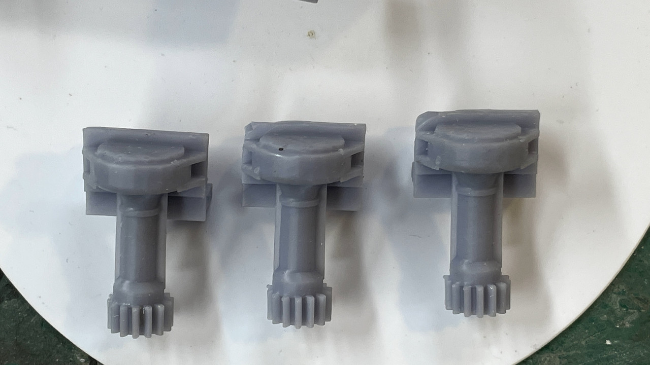
I’ve made a good start.

8 Likes

With my decision to go cold turkey and do it all from sratch, design work has begun in earnest. While I don’t have fully dimensioned drawings for everything, I found another manual that fully details every aspect of the twin turrets and gave me enough specifics about the Mark 28 so I can get many important things right. As a result, I have fully TYdrawn to exact specifications the armored gun house.

The Mark 28’s armor thickness was 2". That’s 0.040" in 1:48, so using that sheet thickness, not only is very workable, but is correct scale thickness. I didn’t have the luxury with the big gun. In 1:72, the 1" wall partitions would have been 0.010" sheet which is too thin to be practical. On the Mark 28, the armor plates are attached to internal angle braces by countersunk bolts and rivets. I was incorrect earlier when I said it was welded. There are a few exposed bolts where the floor framing members tie into the walls. Also I’m striking out finding pre-made 14" drop rungs wirh bolt rings. I already printed them for the big gun and can use the same drawing scaled up to make them for this one. I they held together at 1:72, they’ll do well at 1:48.

I have actual diameter measures of the base ring and training gear so I chose to start here. I also have a section drawing across the ring which I scaled. I placed the profile on a ring that corresponded to the base’s overall shape.

Using the “FOLLOW ME” tool (select the ring, select FOLLOW ME and then select the profile) and the program magically lathes the profile around the circumference. The counterbore and the land represent the lateral and tapered roller bearings on which the rotating mass revolves. I’m not going to detail the bearing. Unlike the monsters in the big gun, these would be almost indistinguishable in 1:48.

I learned how to do internal ring gears in building the big gun, but I’ll quickly review it. I have an add-in to make volute gears. You enter the number of teeth, the pressure angle, and the pitch circle radius and Voila!, it draws a gear as a separate item. It only draws external pinion gears, not internal ring gears. I was able to find the exact number of teeth and the pitch circle diameter of the Mark 28’s, and with those numbers drew the external gear. I also had the outside diameter of the gear which was the inside diameter of the bottom counterbore. I centered the external gear over a filled circle of the outer diameter and INTERSECTED the faces. I now had a drawing of a filled circle with line drawing of the internal teeth inscribed on it. I delected the inside, and then PUSH-PULLED the remainder to the height of the full gear as shown on my scaled cutaway drawings. All in all it took as long to do it as to write this paragraph.

I inserted the completed gear into the base ring.

The last things to do was add the reinforcing ribs and the nut/bolt/washer N/B/W images on the ring flange. I made one rib based on profile drawings and counted the number on the prototype. Looked like there we 32 of them. In SU, you use the rotation tool, with the center placed in the ring’s center. You move/copy a single rib 11.2 degrees corresponding to the gap between them, and then key *31, the program copies the rest equally around the ring. It’s “31” not “32” because you’ve already copied one.

I did the same thing with the N/B/Ws making a set of two and copying them around the ring.

Because the geometry is so regular and one dimensional, I am going to attmpt print the entire part directly on the build plate. It will all depend on the build plate’s ability to hold onto the part during the formation of the base perimeter layers which have the greatest amount of surface area. I those layers stay put, the rest of the print will be no problem. I will only take about 20 minutes to print, so I won’t have long to wait.

If I was printing this part in 1/35 instead of 1/48, it would not fit this way and would have to tilted. Without tilting, there are no supports to deal with and details come out perfectly.

With accurate overall gun house enclosure dimensions and wall thicknesses, I was able to adjust my frame drawing so it was exact. If I was using the kit, I would have to wait until I could meassure it directly before finalizing the frame. I also had the exact diameter of the ring that connects the rotating to the fixed structure and attached it to the frame. I moved the training buffer inboard of the frame extremis to conform to the Mark 28 configuration.

Again, in 1:48, this fits the printer nicely and will be a single part. This ensures perfect alignment of this important structure.

Last part I detailed was another critical one; the guns. I had good profile drawings so I was able to create the correct straight and tapered portions. I added some rifling. There are 40 lands, but did not add any twist. You’re only going to visualize the very outer edges of it. The outer lip of the muzzle is rounded. I will do this as a post-print operation.

I’m trying two print schemes: Directly on the build plate and raised off. Since it’s so symetrical, it can be printed straight up with no overhangs or islands. While it should print directly, I’m thinking that raising it will facilitate liquid resin draining from the bore.

We’ll see which one wins. Unlike the ring gear which had little height, the guns will take over 6 hours to print. In LCD resin printing height is the key varialble in print time.

I found excellent elevation views of the all-important gun mount castings and will tackle them next. Also found good information about the complicated projectile hoists.

I actually need more information about the floor plan of the projectile handling room and the powder and projectile magazines on the 3rd deck.

3 Likes

It shouldn’t be too hard to populate the gun mount in 1:48. I’m going to do a selective cutaway rather than transparent for reasons too numerous to mention. Suffice it to say, I’m not very good at transparent parts. There’s always a blemish somewhere.

I’ve started producing parts with varying success. My first part was the base ring printed flat on the build plate. For some reason, the training gear teeth started to form and then just stopped. A few layers were laid down nice and parallel, but then nothing. I also had some slight delamination. The delamination I could fix, but the gear teeth would be a bit trickier. I could print the gear separately flat on the plate and insert it. Meanwhile, I’ve set it up at an angle and will try again before going with the separate gear approach.

Next print was the main frame. Strangely, one set of supports failed causing one of the frame’s lower extensions to fail. I changed the supports in the slicer and tried again. Here’s attempt #1 compared to attempt #2 which was clearly worse.

There’s a silver lining. The arm extensions are mirror images of each other. By surgically removing the bad arm from #1, I was able to graft the good arm from #2. With some thick CA followed by Bondic UV resin, the graft is invisible and strong. The Bondic is the same chemistry as the UV printing resin and when applied to UV parts welds them. Only caveat is the UV curing light must be able to reach the Bondic so it can be used on blind glue joints. Otherwise, it’s essential in your UV printing tool box. It cures in seconds!

Here’s the removal of the bad arm.

Here’s the part ready for the graft. I broke apart #2 to better expose the arm for amputation. I then trimmed the end properly in a miter box with razor saw so the end was square.

I used the CA to stabilize the part (with accelerator) and then used the Bondic to fill all the gaps.

And after sanding, the part, when painted will show no evidence of being “Frankensteined”… Just made a new verb.

Here are the remains of #2. It served well and saved me a bunch of resin. Resin is not cheap, about $40 a liter. I never throw away rejects and have used them many times to provide repair pieces. I’m creating two boxes… “good parts” and “bad parts”. Often it’s about 3:1 bad to good. 3D printing is an art with a scientific underpinning. I thought I had figured out the failure mode on #2, but the results were worse. The failure still started in the same region some something was going on there. Since I now have a good part, I’m not going to worry about it any longer.

Right now the guns are on the printer and will come off around 7:00 tonight. The fit of the frame ring into the base was very tight. I may have to chain that diameter on the recess a tad so it slips in. They were both created by the same circle so their diameters are exactly the same on the drawing. However, the printing process enlarges parts very slightly, so the holes gets smaller and the ring bigger by a few thousandths each. What was a slip fit is now a no-fit. It’s the reverse with laser cutting. I you cut a window opening and the window frame with the same dimension. The opening grows bigger and the frame smaller since the laser cutting beam has some kerf width, just like any saw only much tinier.

I almost have the gun mounts ready for printing. I drew them over my profile drawing. My first attempt had the cross bracing in the front on the wrong end. I was able to fix it without too much difficulty.

The guns are printing successfully with both setups building straight down.

I redid the ring gear for printing and drew the training worm and pinion. I ended up making the gear with 14 teeth and a pitch radius of 8". It meshed well. Nothing is going to have to move and everything is printed as a solid obect.

Here are the finished drawings of the engine mounts. I saw that there were bolts holding them down so I added those and added bolts to the Trunnion Caps (being printed as a separate item so so the guns can be installed. The bosses jutting out from the side are where all the sighting gear is attached

I did have sufficient drawing to build the training worm and pinion with reasonable fidelity. The worm is driven by a drive shaft from the hydraulics. Manual drive is selected through a series of clutches, but still enters the worm via the same shaft. I’m probably going to use metal shafting for all of them… and there are a ton.

Front view:

And reverse view:

Here’s how the training gearing is going on the printer. As usual, I never print just one. It cost about 20 cents worth of resin for each one and it doesn’t add any printing time. If this was a filament additive machine, the more parts you have up on the machine the slower it is since it must draw each line like a plotter, versus the resin machines that expose an entire layer at once, like a laser printer. I group them close together to facilitate popping them off my flexible build plate.

3 Likes

Guns just came off printer. I was correct. The resin didn’t drain well from the one that was printed directly on the plate and the bore is narrower at the plate end due to “elephant footing”. Elephant footing is the phenomenom created when the part widens at the first five base layers. These are generally exposed at 1 minute instead of 2.5 seconds. The long exposure is used to create the “raft” that holds the model to the build plate. You really want this layer fully hardened so it sticks well. When you put a part directly on the plate, that 1 minute exposuse/layer causes those five layers to widen also. They become wider because the long exposure leaks from the pixels that are to be illuminated to neighboring ones.

The gun with the support’s bores are parallel throughout the print. They’re in the Ultrasonic cleaner now. I will take pictures as I clean them up. I just put the modified base on the printer. It will be done around 10 p.m. Nice thing about printing… I generally like to print overnight so it’s working when I’m sleeping. Unlike string printing where you have to keep an eye on a clogged nozzle, with resin printing, when the part is right and mounted right, and the printer is lined out, it will work without any attention.

From my cursory inspection the guns show no imperfections and should look great.

1 Like

After cleaning you can see the difference between the non-support, direct print one on the left and the one with the supports that raised it a bit off the build plate.

Besides that slight difference in the bore at the breach end, the rest of the print is perfect and not different between the two. They’re getting post-cured now and only a very little cleanup will be required to create some beautiful guns. There are no layer lines and they ARE NOT warped that I can see. I’m quite pleased. I will not have to get machined barrels.

Once they’re cured, I will take a diameter reading at the slide end and use that number to draw the bore in the slide, plus some clearance tolerance. I don’t want a press fit. If I wanted to, I could make the guns able to recoil, but I probably won’t. This will be enclosed in Plexiglass and never be touched to play with it.

Onward and upward!

6 Likes

Phenomenal work with the ring gears!

Recently I had to replicate a late revision drive sprocket for the M1 Abrams tank. It’s all arcs and curves and angles, and if there’s an add-in tool for creating things like that I wish I knew about it. Not having access to the real steel, I had to recreate it in 2D CAD the hard way, via pixel counting. Rendering it in 3D later turned out to be the easy part!

If you know of any tools for simplifying this kind of thing, I’m all ears.

Can you send some images? There are many ways to skin a cat in SU. If I can’t do it, DaveR surely can. He can do anything.

2 Likes

It got done in the end, but at the time I sure did wish there was some automation tool to make it easier! :grin:

1 Like

Nice work, I saw this on your tank build thread. I assume you tackled this as componentized radial slices on an 11 or 22 sided circle?

Hi. IIRC, I imported my original 2D CAD drawing and then push/pulled it to the correct depth before applying the finishing touches, such as the sloped/angled rear face of the teeth. But once I had it near enough correct in QCAD it became pretty easy to derive the 3D model with SUP.

Also, yeah, the 2D drawing was based on a circle with 11 radii. QCAD is very good at making these operations simple enough even for dummies like me. :grin: After that came the tedious hairpulling of getting the arcs and curves the right size and shape.

There’s so little accurate info available on the real objects that you have to apply really laborious methods, such as breaking pixels up into sub-pixels, just to get everything to look right. Add to that the necessity for accuracy due to it being the basis of an actual working vehicle and you’re in for some long nights of suffering.

Sorry to hijack @mmarcovitch’s thread! These gun turrets are incredible work and I salute you! Definitely museum quality.

1 Like

How long before the barrels are fully cured?

I cure them for 15 minutes. You can over cure stuff. I use an 80/20 mix of Elegoo Mars ABS-Like Gray Resin and Siraya Tenacious. The Tenacious is fully flexible and the Elegoo can be somewhat brittle. The mix gives good impart resistance so a drop to the concrete shop floor doesn’t guarantee destruction.

This is a two-day post so there’s a lot to go through here.

The reprinted ring gear was excellent, one slight area needing fixing. I fixed with Bondic. It fits the mounting ring on the frame well and the two can rotate. The real one has retaining clips that grip under the training gear and I’m going to duplicate so the turret will be positionable. I found that the Training Buffer interfered with the ribs on the stand, I surgically removed the offending material. I found another drawing of the buffer and it looks like the back is relieved for the same reason.

The mod: I also replaced the printed plungers with steel. One didn’t form right and after replacing it, I did the other to match.

The gun mounts printed well. I always make more than I need and one set had a fatal defect. Didn’t matter, I had three more and only need two. As printed off the machine.

Finished set: Not glued, just set in place.

Printed a gaggle of trunnion caps. I erred. I put two bolts on each side. There is only one… Not going to worry about it.

Here’s the caps placed on the mount. Again… not glued. Can’t do that until the guns are in place.

Here’s the one that failed. And you can see why. That support failed. When the support fails it usually leads to a local or catastrophic failure depending on how strategic the support is.

I also printed successfully, three out of four Training Worm/pinion assemblies. Only need one. This one was also a support failure, but of the more catastrophic variety. It left the partially formed part stuck to the FEP film at the vat’s bottom. The new version of Elegoo’s FEP film is very forgiving. Stuck parts pop off with no damage to the film. I can run for months without having to replace the film … a 20 minute job. Looks like something that didn’t make it through the Star Trek transporter too well…

Here are the good ones. Even among these there are some that are better than others. Always make more than you need!

Here’s the trial fit top view. Part has NOT YET been finish sanded and you can see by the support marks on the top.

And the bottom view showing the pinion meshed with the training gear.

That’s all the parts that are drawn to the point of being able to print. There’s a whole lot more going on in the design department. I finished the gun shield and elevating sector gear, but both have to wait until the gun proper is finished. There are some brackets that engage in the gun that can’t be finalized until gun is done. I also started delineating the armor housing with the curved back plate. I’m going print the hatches with their hinging, but the curved wall will be 0.040" styrene. Technically, the armor on the this ship’s secondary batteries are 2.5" which is 0.050" in scale. I may laminate 0.040 and 0.010 to make fifty. Laminating also helps maintain the curvature. I had to extrapolate the lateral position of the hatchways due to the curvature of the image. I then flattened the curved piece using SU’s “UNWRAP & FLATTEN” facility.

The gear teeth are finer on the prototype, but at 1:48, if they’re too fine, you won’t see them.

Here’s some WIP shots of the rear panel. I’m not sure if the hatch is curved. It too a while to create the curve using a copy of the wall section to cut the inner and outer faces. If flat, that’s much easier to do in styren. In addition to the crew hatch, there are four others for the cartridge discharge chutes.

Here’s the wall flattened as a test.

There are angle bars that attach all of armor panels to shape the gun house. I’m going to 3d print these with fasteners. My shape isn’t exactly right as I’ve ssen on some video footage. Don’t know how ■■■■ I’m going to be about it. The fastener pattern’s probably not right also other than it’s a combination of rivets and bolts.

Here’s the actual back do. I’ll print the foot rungs too. Hatch looks flat. This is the lower discharge port. The six bolts to its left are those that are holding the housing to the longitudinal frame rail.

Now the gun. The geometry is a killer for me! I don’t have any drawing of the parts separated, e.g., slide, housing, etc. I was very difficult for me to visualize just what parts move during recoil and what parts are fixed. When you watch videos of the guns firing, the recoil is so fast you can’t stop it when recoiled. I suppost you could copy the video and do some frame-by-frame editing, but my bet is that it would highly blurred.

The real of the housing is curved in two directions… sort of part of sphere. I first had it curved only in the vertical direction, but realized it was wrong. To do compound curves in SU, I find it easiest to create a cutting too of the right shape and use it to shape the object. In this case, I created a segment of a sphere and placed it so it would remove the right amount of material.

After cutting I grafted the part to the rear of the gun frame and it actually worked out. Still have lot of details to include and am constantly checking that the object is still solid and printable. Last night started working on the rammer hydaulics. I used one of my drawings a as guide only to find it was completely wrong for the reservoir. Found others that were accurate. I spent almost 8 hours yesterday just doing drawings. And I have hours and hours more to go. Taking the day off to go see Openheimer.

9 Likes

This is fantastic!

I was able to find FREE deck plans of the USS Missouri in 1950 configuration when it still had all the 5" gun mounts. I was able to load up the main, 2nd, splinter and 3rd decks into SketchUp and display them in full size… you read that right… in SU this file is a ship 887 full length measure. SU doesn’t care. I also had profiles of the exterior and center line section. With these I was able to line them all up and finally understand just where everything is going to go. I was also able to size the Ready Ammo Handling Room that supports the turret, and the elusive powder and projectile magazines which do not lie directly under the guns.

The 2nd deck has no gun handling apparatus as does the splinter deck. The splinter deck is a shallow void space to catch any explosive debris before it gets to the delicate spaces below like boilers and magazines. I used the 16" barbettes to register the drawings since the lower decks have overall sizes that are slightly smaller than the main deck due to the ships lines. You can find those plans here: USA - BB-63 USS Missouri Booklet of General Plans (1950) : Navy Yard, Norfolk, Virginia : Free Download, Borrow, and Streaming : Internet Archive

When overlaid in correct resgistry I am able to model in full size the paths of the curved powder and projectile hoist trunks. These trunks are designed like this deliberately to mitigate fire from spreading from the upper decks to the magazines.

And I was able to accurately scale the Ready Ammo Room both in area and height by matching to the full size floor plan.

I erred in my design by including a lip around the rooms roof. It is flat.

I also found very good data on the design of the Quick Acting Watertight Door (QWT). It took a while to search through hundreds of images until I hit on a sight that manufactured the style used by our Navy with great head on images on which I could draw the door. I also took screen shots from Ryan’s USS New Jersey video “Doors”. With these sources I was able to create a very respectable prototype.

Here are the three drawings I used:

Outside:

Inside:

And then the best… the door without the hardware where I could get good fixes on the positioning of the dog pivots.

This was a closeup from Ryan’s vid. It shows nicely the roller dogs.

I drew the door in layers and 10X scaling. Sketchup has a trouble with working with curves especially when doing contours in FOLLOW ME. If the segments are too small, it leaves them out and makes holes, whereas when enlarged it fills them complelety. When you shrink the drawing back to original size, the filled areas stay put. I don’t know why this is, but it is. To make those bulges, I produced external rounded rectagular shapes and internal ones and bonded them to the drawing on both sides ensuring that there was some material thickness between them. They’re printing now, so I know if there was enough material to produce a viable part.

I then produced the frame as a component and finally overlayed the dogs and all their operating links. Some of the links were challenging since they have curves that enable them to clear the other parts.

And here’s the finished product showing both sides. The real door has an extension lever on the wheels to give more torque. These would be too frail for printing and I’ll attempt to add them with wire. I am attempting to print the doors as a single part. I will see how that works out. I also had to thicken everything. At scale thickness many of these peices would not be viable. The beauty of 1:48 is you can really lay on the detail and have a reasonable chance that it will show up.

As usual, I print multiples. I will probably need at least this many. I’m also contemplating printing the entire rear curved wall of the gun house including the hatchs and details. It might be the easiet way to go if it all fits. Otherwise, I’ll print the curved corners with rabbets to seat the styrene walls. That will work to, but won’t be as elegant.

Whew! That was a load of stuff. Now I’m goint to check on the print which just finished. Let y’all know how that worked out.

Print was marginally successful. The handwheels failed as I expected, and rollers failed to form on the bellcrank extensions. They were highlighted in pink in the slicer, but I thought they’d make it. I’ll print the handwheels separately and add them post clean up. And I’ll get some supports to those rollers and print again. Otherwise, they look pretty good. All the arms and bars printed.


6 Likes

WOW! Just WOW!

Swoons with envy.

1 Like

The reprint looks good, but useless! The door I drew is not used in the magazines. Jim Slade and Ryan sent me photos and information about the magazine doors. They’re not quick acting, but have individual dogs and they’re much smaller. I will share and keep the full-size QAWT door since it’s used a lot of places onboard ship.

Based on information from Ryan and Jim Slade I completely redrew the magazine doors. There appears to be two types, both smaller than the standard QAWT that I drew eariler. They’re the same width (26"), but significantly shorter at 45". They are also locked by individual dogs (8) and have the pass-through scuttles where the powder canisters are passed from the powder magazine into the projectile magazine where the dredger hoists are that take both (separately) up to the ready ammo handling room.

I’m going to print the door complete with all the levers attached. I believe it will work as long as I don’t break them all in handling. I can always subsitute wire (I did this in the big turret).

Here they are installed in the partitiion that separates these two spaces. There’s still a ton of work and research I need to do on them to make this a viable model.

The larger doors have a 7" sill, whereas these have a 24" sill requiring the step to make them easier to negotiate.

Here’s the opening side. The floor plan shows which direction the door swings. I now know that the black bump on the door’s symbol is the scuttle in the middle of the door. There is also a line on some of the door symbols that shows the handwheel of the QWAT door. Then there are the rest without specific symbology which I have to figure out.

Here’s how they’re going to be mounted on the printer. I’ll put them on tomorrow. Print time is less than two hours.

5 Likes

What printer are you using?

Elegoo Mars 3. 4K monochrome LCD, reasonably sized platen. I use a Fulament spring plate which has great adhesion and really speeds up going from one job to another. I usually print at 0.040mm and, with my Elegoo ABS-like (80%) and Siraya Tenacious (20%), each layer takes 2.5 seconds. I did resolution tests to verify that number.