5" 38 Twin Turret Cutaway

Haven’t printed the new doors yet. But I have been busy. I nailed down the turret curved back with all the doors, hinges, latches, foot rungs and bolt heads. I did it at least five times until I got it right. Each time I thought I had it all tied down, I’d put the STL version into the slicer and then would see something was wrong. Either some details were imbedded too deep or not deep enough, or they tilted in some way. The I saw that I didn’t use enough segments on the curved surface and it looked terrible. Then when all that was done, I found that somehow the pieces was about 3 scale inches too narrow. So I to fix too. All told it took much of yesterday and today to get it right.

SketchUp does not actually draw curves. It draws a series of straight lines that approximate curves. For circles the default is 24 segments. That’s quite clunky and in 1:48 would be very noticeable. To fix it you’d have to sand all the peaks down to curves, but all the details are part of the print and they would get in the way. For the tools that make curve parts, the default is 12 segments. When I’m doing a surface that I want to print almost a true curve I go minimum 48 and even better 96 segments. SU’s computational engine works harder the more segments that curves have. For graphic display purposes, SU smoothes the curves, but the segments are actually there and when you export as an STL, there they are.
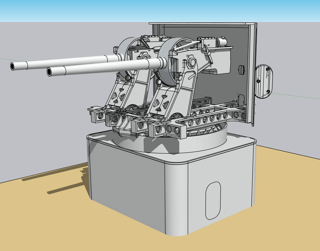
Here’s an example:

The drums are R-L 24, 48 and 96 segments. With the curve smoothing they look like perfeect cylinders and if I were to print or render this, it would look great.

When I turn on “Show hidden surfaces” you see the segments, although the surface is still smooth.

But after STL conversion and loading into the 3D slicer, this is what the cylinders actually look like. In 1:48 that flats will be very noticeable.

One of the most difficult aspects of drawing the back wall was putting the details onto a curved surface. SketchUp works on an X-Y-Z coordinate system with X being the red axis, green the Y axis and blue the vertical Z axis. It is always best for many reasons to orient your drawing with the these axes which facilitates moving things around. That works great on a rectangular object with 90 degree corners. With a curved surface like this wall, only one spot in each quarter turn aligns with the axes. I drew all the details off the model, ensured they were each printable solids and then embed them in the curved wall’s surface. I actually push them into surface just a bit to ensure that the details don’t form detached in space. I they have separate supports, which many will, they could completely form, but not part of the print. When the wall surface is not on axis, when you move the object in the x or y direction it moves in an angle. So if I wanted to put the part in a specific location, I had to zig-zag and creep up on it. It took a long time.

Then about 3/4 the way through the exercise, I decided to copy and paste the completed wall to the master drawing. When I placed the wall against the rest of the gun house I drew previously. It didn’t fit! Frankly I don’t know when the size change. I say “changed” because the original curved wall was that gun house’s back wall which I copied and then added the two scale inch depth. This image shows the first wall I drew superimposed over the corrected wall. This difference was unacceptable. The side walls have to intersect with the 0.040" thick side walls with no gaps.

Here’s a vertical look at the wall over the main frame. Again, the wall has to key into the frame correctly. The new wall is on the frame and the incorrect one behind it.

I couldn’t just stretch the wall to fit. I had to start over. However, I was able to take all the details off as a group and preserve them. That sounds easier than it was since they were on slightly different distances from the center and lying on slightly different radii. Lots of trial and error. Notice I’ve thought ahead for a change. I included the mating flange that will connect to the straight side walls. There is angle brackets on the real turret that do the same thing.

Here’s how the finished product will look. Notice also the curved angle bracket that secures the floor and back wall to the frame. This is not the fianl look for this part. I have to study the pictures and drawings more.

And the finished front.

And in a more rendered way.

Here’s how the wall fits on the printer.

I’m using heavy supports on the wall itself and a lot of them. It’s not that there’s that much surface area, but it’s a bit heavy and that weight starts to play a part in the support scheme. All the details are supported by fine supports. Notice how fine the facets are on the surface using 96 segments. Very light sanding will remove them entirely. In 1:48 you can include ALL the detail.

While the attached foot rung will print, I’m worried about thier longevity, especially the ones hanging down below the lower edge. I will surely break them off. I am printing them in bulk so I can replace them if necessary. I’ve included a 0.020" stub on them that will fit into a drilled hole. Each rung has to be supported separately. I can make many of these fairly fast.

We’re heading back East on Tuesday. I may do some work tomorrow, but after that we’ll be gone a week.

6 Likes

My approach is to essentially do all modeling directly in the “master drawing” itself to be sure that all components fit their neighbors (which is usually quite easy thanks to SketchUp’s inference feature), and any errors are immediately apparent before they propagate.

The above is not quite true for my workflow due to the complexity of the actual master drawing (15 million entities or so, with about 1900 unique components). It is way too cumbersome to work with for modeling purposes (saves take about 2 minutes on my computer). I create each major subsystem in a separate SKP model file, starting with a few location-reference components copied from the master SKP model and pasted-in-place into the separate subsystem SKP model. Then I create the subsystem geometry in the separate subsystem SKP file, being pretty sure that everything will fit into the master model thanks to the selected starting reference components. When the subsystem is completed I copy it and paste-in-place into the master SKP model. Each subsystem typically ends up with on the order of a million or two entities (across 200 or 300 components), which is borderline manageable on my computer for doing editing and frequent saves.

2 Likes

I’m doing that now. I find that it’s just too many things to pay attention to when working details on the master drawing, but I must keep checking back to that to ensure stuff fits. As you’ll by today’s output of the printing of the big curved wall, that a couple of the failures were dur to drawing errors and I thought I had it nailed down. Oh well…

I finally unloaded that batch of QAWT doors and they did come out pretty well. The handwheel cross bars are almost too fine to hang together, but even there I did get some successful ones. The operating bars are so thin they’re kind of floppy and if I were to do them again would make them about 2X thicker. As I’ve said before, real world material sizes sometimes don’t translate successully to the model especially at 1:48 or smaller. Regardless, I’m happy with them. They will work and I don’t know where to put them in the model. It gives me confidence that any other doors I produce will work.

And the flip side. All the major supports were on the front side and the only supports on the mechanism side were supporting the dog rollers and removal didn’t damage anything to badly. I hadn’t don final sanding on the edges.

And here’s the second one I cleaned up. I still have four more that I haven’t trimmed that are in the spares box. This one did have the edges sanded. When primed and painted they should look pretty spiffy.

When I woke up this morning and did my usual model ideating, I realized that I could use the backing plank that I use for the ladder rungs as a drill jig to add them manually. The correct spacing is 11.5" and I had arbitrarilly a little over 13". I redrew the layout to have that spacing and set it up for printing.

Then, this afternoon, I put the back wall in the printer. 6 hours later here’s what I got. It wasn’t totally bad, and, in fact, since it’s quite an unusual piece to print, I’m not too upset, but there were some weak points.

Here’s as it came off the machine looking at three views. I had removed some of the supports around the delicate details, but did not post-cure.

On the left corner there was some distortion. I don’t know what cause it, but it’s usually a support failure. I will have to evaluate whats going on in the slicer. The handles and steps all formed nicely.

Note the delamination of the base raft! That’s also strange showing there was good adhesion to the build plate. Could be too much attraction to the FEP.

No distortion on the right side!

And the back. Strange things were going on in the back.

Some remarks about this…

I thought the drawing was finalized, but the latches on the right side cartridge chutes moved out of position. The center section bolt heads are not there. That too is a drawing error.

BTW: As predicted, I already broke those bottom two foot rungs. I will have to add them late in the build and maybe make them out of metal.

In the back, the right side latch dogs were not attached to the surface. Remember was I was saying about have to be sure their embedded in the drawing. Well… I guess these weren’t. I was able to put them back using Bondic, but I’m not keeping this part for the model. It’s going in the scrap box and will be used for parts if necessary.

And then there’s these malformations. I’ll have to explore this defect. Because it’s actually more material, I can grind it off if I need this part.

I now have the powder handling doors in the printer. They’ll be done about 11 p.m., but I’ll get them tomorrow. If they come out as nicely as the QAWTs did, I’ll be happy. If I can’t get the curved wall to print effective, I can print the add-ons and build it out of styrene. There’s always a way!

Do you have SketchUp set to hide the rest of the model when within the editing context of a component or group? If so, then everything else is visually eliminated when working on the geometry of a given object. It is common for some objects to occlude others when looking at the overall model. To deal with that I use a combination of temporarily hiding other parts of the model, and layers/tags to hide pre-defined sets of objects.

I virtually always use the “Dave” method of editing scaled-up instances of components, rather than editing the 1:1 size instances in the natural model. I move those 100X instances up a ways in the model space (and leave them there, along with a Scene to quickly jump the camera to view the large component). There is generally empty void space all around such large-scale instances, so no visual interruptions.

1 Like

I do all of those things. And I have used Dave’s wonderful method, but occassionally forget about it and fall back to my old habits. Maybe that comes with age… I’m making good use of the “tags” feature as well.

1 Like

This is looking really good, why not use wire for the door handles and hand railings? Or do you want to print everything.

1 Like

Not necessarily. My first choice is print because I can shape. More closely to 1:1, but I will always fall back to wire. I may do those over-hanging ones in metal just so they’ll stay in one piece.

Cool, keep it up!

Thanks!

After studying the part set up AND the part’s design itself, I modified the rear panel and then changed the setup on the printer. For the part redesign, I added ribbing and buttressed the corners to stiffen the structure and add more beef so the styrene flat walls have more contact surface. For the support setup, I placed the part on the plate simply tilted back and not slanted. I removed the bottom ladder rung since these broke off almost immediately before, and even then, am printing dozens more that I can apply much later in the build.

This in looking at the inside. You can easily see the added material to stiffen the structure. Top now forms a lip so the roof can set down inside the back wall.

And here’s the front view showing the individual light supports picking up the exposed details that showed up as trouble spots in the slicer. I’m making the piece with and open hatch for more interest.

I printed them today and here’s the output. I will use this. As I expected, the foot rungs didn’t do so well and I lost one door dog which can be substituted with 0.010" wire.

The rear still shows one of those odd bulges as happened in the first attempt, but this one seems easier to remove. It does not show up on the front side. And there are not print lines in the front surface. It’s a pretty good print all in all. The inside door dogs printed nicely… amazingly. That delamination on the bottom rib is not a worry either and easily fixed with Bondic. Not worn wasting the resin on another print. This was post cured, but not final sanded.

I have the ladder rungs printing now and have another crack at those powder magazine doors. With these printed I have to get back to the drawing board and produce more parts.

I’m going to be making a clinic presentation on the Construction of the 16" Gun Turret at our Military Modelers Club of Louisville Regional Modeler’s competition being held on Friday thru Sunday, September 21–23 at the Triple Crown Plaza in Louisville. I’m titling the presentation 21st Century Modeling: Model Building+CAD+3D Printing. There are going to many vendors and exhibitors. It will be a wonderful show.

4 Likes

In a messaging session with Ryan Syzmanski, we’ve decided to model the magazines in an “artistic” rather than prototypical way. Due to the intermediate non-functional deck spaces (non-functional regarding ammunition movement), I’m going to model it based on this iconic drawing.

My model will be more detailed and accurate than this image. I also suggested to Ryan that we display a graphic to show the actual relationship between the turret and the magazines which do not lie directly below any turret. There are two decks between the main deck and the magazines that would not add value to the model.

I tried out my new V-Ray rendering software which came with the SketchUp Studio version that I’m now using. It’s significantly better than Podium which I’ve been using before.

Here are two examples:

First Podium: Podium handles the details okay, but really shifts the color.

Now V-Ray. V-Ray drops out the background based on selections you make. This is actually quite useful for embedding images into documents. Sharpness is the result of the image size you’re outputting. In this case I chose a small file size. It also renders much faster than Podium.

And now a screen print directly out of SketchUp: In some respects, the SU direct shot is more descriptive showing all the line work. I can display it without the lines and it looks more like the renderings.

As you can see, the gun designs are almost complete. I was drawing all kinds of details based on one of my references and then realized that the reference drawing was of the gun slide, not the housing that surrounds it. The flanks of the fixed part of the gun are relatively clean. It saved me a lot of drawing time. The hydraulic piston that operates the ram, which I was trying to depict, isn’t simple. The ram is tied to a gear rack which multiplies the stroke length. The rack then operates the ram with another rod. All of that is hidden by the outer housing.

I got a nice print of a gaggle of ladder rungs. Only one did not print well due to on support letting go beneath it. I chose to post-cure BEFORE trimming the supports to strengthen the rungs to better handle the support clipping function. We’ll see…

I spaced the rungs on their support bar exactly on the 7.5 scale inch spacing as they sit on the turret. I can then drill at each point after removing the rungs and have a convenient drill jig to drill the mounting holes on the turret flanks. Now that’s thinking ahead, ain’t it? I designed the rungs with a stub end that is sized for a 1/32 drill size. It should work…

I’m finalizing the cutting patterns for the styrene turret parts. I had some clearance problems which required adjusting the gun slops on the faces. I also printed the size access hatches with their hinges, mounting bolts, and grab handle. Only one out of three printed well. Again, I used medium supports for the base and some failed causing deformation. I’ll adjust it and redo. Need to order some more resin.

4 Likes

V-Ray is excellent. I haven’t tried any other 3D renderers, but I found V-Ray to be relatively simple to pick up and use. There are a million options that are way beyond my skill level right now, but even the most basic functions return some great results.

Saul, Does V-Ray have materials that are specially designed for rendering like Podium does? I used some brass that was on an object in the 3D warehouse, and it looks like a fountain fill that I would do on CorelDraw. In Podium the brass is reflecitve like chrome where it will show objects in the room around it.

I got the gun drawing done so it’s about as good as I’m going to get it. I had Ryan take a look and he said it would work and was surprised to see it all naked.

With a decent drawing I was able to print it. The barrels are already printed. I had a choice to make of printing the entire gun assembly or print the shield separately. After attempting to install it in my mind, I didn’t like how it was going and printed it as a single piece. In actuallity, the shield assembly printed reasonably well. I chose to remove the trunnion pins and will machine them out of aluminum to the .147" diameter on my lathe. I drilled the holes a little deeper to accept them.

Notice the phos-bronze hydraulic lines to the rammer piston. My resin printed ones didn’t. It appeared that the pipes were not actually joined to their flanges in the drawing and they failed to form correctly. Better with metal anyway.

The trough that accepts the projectile and cartridge did not form. It was paved over with a resin sheet. Not sure where it was coming from. Drawing that trough was difficult for me, so instead of redrawing and reprinting, I used the Dremel with flexishaft and a spherical diamond-coated burr, and carved the channel back in. These will be partially obscured with a projectile and cartridge load. The back left edge of the curved shield was slightly missing, but was rebuit with Bondic.

Another view of the tail of the gun showing the trough. The trough and the sloped shelf next to it are brass on the rear gun to avoid any sparking.

The real test was how well the gun fit the slide and how well the slide fit the mounts. For the former, I had to open the gun opening much deeper. There was some errant resin growth inside. I tried using an appropriately-sized drill, but it wasn’t working well and I was afraid I would break something. I then turned to another diamond burr and ground it out. The diameter of the shield and front of the slide was perfect. The gun was a sliding fit.

As to the fit into the mount, it was perfect!

When painted these will look pretty good. I loved how the gear teeth formed on the elevation gear. Out of the four guns I printed (2 R and 2 L) one pair is good enough to use. I have some more metal works to add. A couple of the handles broke off on the side operating lever. I just thought of using some very thin shim brass to actually line the trough with real metal. I will experiment on one of the reject guns to see if that works.

So folks, WE HAVE GUNS!

I also finally decided to build the model exactly as it is in the ship. With the magazines correctly offset and in the correct deck, it will occupy a display space of about 1’ X 1’ X 1’ and that’s really not too big and much smaller than the 16" monster.

Next up will be to design and print the hydraulics and sighting gear that really complicates the turret. Then I’ll start working on the Ready Service Room and the projectile/cartridge hoists. I don’t have any good references on the structural steel that supports the hanging central column and the hoists attached to it. I did get a properly sized piece of brass tubing that will serve as the central column.

3 Likes

I don’t know the answer to your question about V-Ray materials. What I will say is materials in V-Ray have a wide range when it comes to the rendering of metallic surfaces, and for absorption and reflectivity.

Here is a quickie example of some basic shapes with the reflectivity cranked up to 11:

You can vary the metallic/dielectric characteristics of the materials as well as the reflectivity.

Here is the Materials section of V-Ray’s Asset Editor:

thanks! That’s very helpful. I will work with it. I also need to watch the tutorials.

The granularity of the control is such that you can tailor the result pretty accurately.

Hope everyone had a nice Labor Day weekend!

I machined the metal trunnions along with the seal for the trunnion bearings on the real thing. Simple turning operation. The pin size was .147" and I had to deepen the holes on the gun housings to give more meat in the junction. I made the pin’s depth is just about .200". I machined the first set using a collett for the 1/4" aluminum stock. The collett did not have a thru-hole, so I had to cut the stock fairly short so it wouldn’t extend too far out of the collett. I machined the trunnion pin diamter first and the inner surface of the seal. I then mounted the pin in a three-jaw chuck and finished the outside of the seal face. He I’m test fitting the gun frame onto the pin. My little Taig Lathe is in need of a new motor. The lathe is at least 30 years olds and the motor’s bearing are shot. There is about 1/4" end play and it’s vibrating like crazy. It’s amazing that it’s not destroying the cut quality, since the whole machine is vibrating together so the cutter and the stock are also vibrating together. It’s just very annoying. I can get a new motor from them for about $160.00.

I tried the finished part on the gun in the mount.

There are screws around the seals perimeter, but I’m not going that far.

Here are the four trunnion pins/seals. The two with the holes will accept the manual firing mechanism that feeds through the trunnion center so the gun can elevate without disturbing the mechanism. The manual firing mechanism is quite complex due to the interrupt system that prevents firing the gun when it’s pointing at any part of the ship. The gun is only firing mechanically when the entire firing system is out of commission. Normally the firing is electrical and remotely activated from the secondary plotting rooms.

I finished the metal hydraulic tubing on the guns. I removed the one I did last week. It was not the accurate and needed replacement. I also finished opening up the bore for insertion of the gun barrels and the cylindrical loading tray. The hand levers are breaking off due to all the pushing and shoving I’ve had to do to fit the guns. I will replace with metal.

I need to design more parts before I can go further.

8 Likes

Epic work there.

Thanks Saul,

Finished up with the guns for a while until painting and assembly. Added or fixed the broken levers and handles. I permanently glued the gun mounts to the frame. It’s okay to do that now since it makes a stable assembly for further work on all the ancillary equipment. I also got the rammer hydraulic lines in place and replaced the first long one with a more properly shaped one.

I cut out my gun house patterns, applied a light coat of MicroMark Pressure Sensitive Adhesive and stuck them onto a large piece of 0.040" styrene sheet. This represents about 2" in scale, close to the scale 2.5" armor on the gun house. Instead of using the right and left side gun house templates, I just cut one and used it to trace the other side. I then clamped them together and sanded their edges lightly so they identical. When possible, I used the corners and edges of the sheet for at least one of the sides.

Here’s a closer look at the gun house side…

All four of the top pieces had to be exactly the same width and the gun slots had to line up. So I used one of them to trace the other three, even though I had drawn them and they equal in the drawing. This eliminated the slight variations that would crop up depending on which side of the line I was cutting. I got most of them cut out today. I tried the sides onto the 3D printed curved back wall and was rewarded that the corner rabbett that I printed perfectly blended with the styrene sides. I don’t have any drawing stuck onto the side piece that I traced, but I will need the location of the side access hatch. For the actual hatch cuts I will trace the real one. I’m also going to located and drill all the holes for the foot rungs while it’s all in the flat. I have to do some finish sanding on the edges and the gun slots. I also have to sand bevels on the mating surfaces of the angle pieces so they mate properly. All joints will have 3/16" styrene angle as does the prototype.

Meanwhile, while printing parts for another project a calamity happened. After a major print failure… and I mean “major” in the sense that the only thing that printed on the build plate was the base raft. All the rest was a series of variously shaped blobs stuck to the FEP teflon film at the resin vat’s bottom.

I was able to remove the ■■■■ on the bottom without destroying the FEP (I hope), then I looked at the LCD protective plate and saw a series of bad cracks propagating across the LCD. I thought it was the tempered glass protective plate that I bought to protect the delicate LCD below. But when I removed the undamaged cover plate, I realized that the cracks were in the LCD itself. I did a light test and it failed miserably. Half the screen was disfunctional. The cracks are quite obvious in this image. I need to understand why the print failure happened in the first place. I’ve tried printing this part three times with not very good success before the complete mess that this attempt was.

I ordered a new screen from Amazon which will be delivered soon and I’ll install it on Monday and hopefully, all my projects will continue uninterrupted. Elegoo has a new machine out that uses a Texas Instruments DLP chip. This device has been around for a long time and since it projects its pixel image though lenses and mirrors to the resin vat and doesn’t get any physical pressure from the z-axis lead screw and stepper motor. It was the plate attempting to compress those hardening lumps on the vat’s bottom that caused the damage to the LCD screen. I think my next printer is going to that technology. So this summer I’ve added a new motherboard, new touch screen and now a new LCD screen. Wish me luck. I can continue to build the sheet work without the printer running, but I really need it.

I found out from Ryan today that the splinter deck is only 30" high, made up a massive series of square compartments with manholes separating each of them. I will only be showing a little bit of that detail. It’s only function is too isolate the magazines below from any shrapnal that may attempt to get there from action above. I don’t believe any of the Iowas saw any action that involved this structure.

3 Likes

I spent almost my whole day on the drawing board (well… virtual drawing board). I’m working on several fronts at the same time. Today’s work centered on figuring just what kind of cutaway will be needed to show the magazine buried three decks down, while showing some of the intervening spaces. It’s not easy and construction will also be a challenge. I also scoped out the wooden base and the plexiglass case. The base will require some lead time so I’ll have to get that constructed earlier than one might think. My last base was done by a dear old friend who lives in Albuquerque. He was the bass player in my band and an exceptional woodworker. I’m not sure I want to task him to build another. He’s in the process of scratch-building a stand up double bass. Just to clamp the skins requires 54 screw clamps which he just started constructing from scratch also. He’s just as passionate about what he does as I am. (or obsessed…depending who you ask.)

There will be lighting to illuminate the shadowed areas. There will aslo be compartments under gun ready service room. The main deck will be planked. There will be no furnishings on the intermediate decks. I think it’s pretty neat that V-Ray renders materials that are loaded from my older rendering engine, Podium. I renders much faster than Podium for these test runs.a

It’s one thing to cut openings in a SketchUp drawing. It’s quite another to cut them in styrene assemblies. In some cases the former is easier, but in others the latter is.

Before I could start gluing together the turret parts cut yesterday, I had to do a few more design steps. I wanted to cut the opennings for the side access hatches and telescopes while still in the flat. I also want to drill for the foot rungs. I also located the officer’s hatch on that small flat roof piece. I was able to cut one hatch opening and clean it up. The printed part fits nicely once I spent some time with needle files to finalize the shape. The hatch drops into the opening and the hinges sit on the surface. If I want to open one of these, I’ll have to reprint with a different hinge orientation.

BTW: In handling the hatch, the handhold broke off. I’m going to be replacing a lot of these with 0.020 wire.

Here’s a closer look at each.

The left side with the hatch out of the opening.

If I would have planned ahead a bit, I would have included these details in the patterns I used yesterday. 20/20 hindsight. “If my foresight was as good as my hindsight, I’d be better by a ■■■■ sight!”

Here’s the next pattern with the telescopes for the left side. The left side has two openings: the forward one is for the pointer’s position, and the rear for the sight checker. The sight checker uses that telescope mostly for training purposes to evaluate how well the pointer and trainer and managing their positions. I will be 3D printing the hoods for these telescopes. Their flanges go around the perimeter of these openings.

And here’s the officer’s hatch opening. I’m going to fabricate the counter-balance cylinder out of metal.

There’s one more series of parts that’s required in gun house construction; There are flat shield on each side of the curved gun shields that seal the curved surface from environmental incursions especially seawater. The curve of the shield covers the curved gun shield. There are two per gun side and then a bottom piece to tie it together. The upper edge is connected to the turret roof.

I used the gun shield in SketchUp in a sectioned drawing to capture both the curve size and position AND the interface with the roof. I can be pretty sure that this works since all the prints were produced from the same drawing. While there’s some minor size change in the printing process, it’s really insignificant.

Here’s an interesting shot of refitting the armor on a 5" turret when refitting the Iowa in the 1980s. Based on this picture, I need to slightly change the lower left corner of the telescope opening. It’s not a curve, it’s just an angular cut. In this image the guns (without barrels) are fully elevated. Really shows how the gun house fastenes to the main frame. Also good views of how the pointer’s machinery is fastened to the frame.

2 Likes