I was able to get good parts for the projectile hoist after three tries. The first, for some reason, came out 20% over-sized. Something occurred when I made the scaling in the slicer. I don’t think it was loading the wrong factor (2.08%), but rather was my entry. I may have double-clutched and got an erroneous value.
It was a shame. It was a pretty nice part.
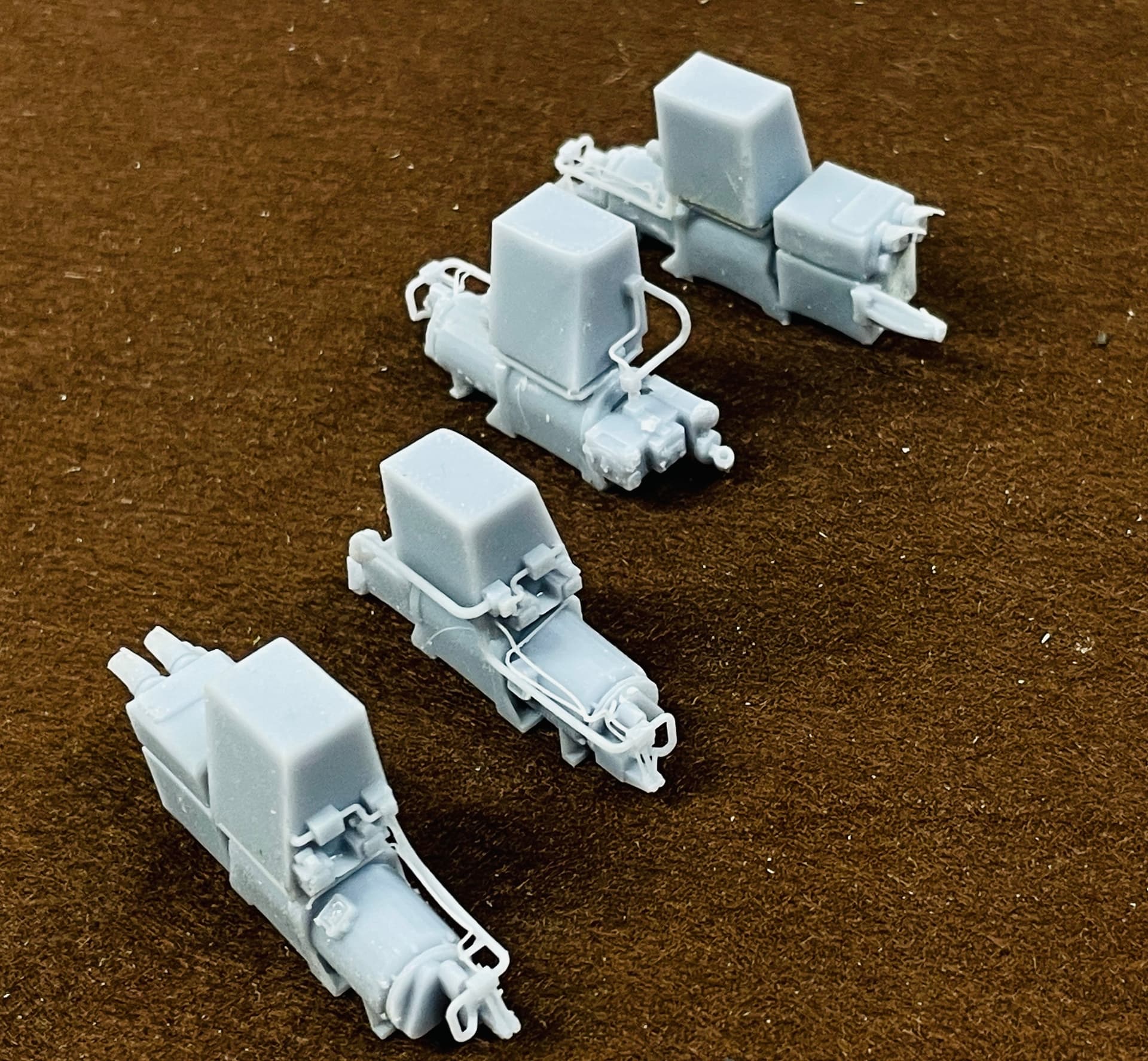
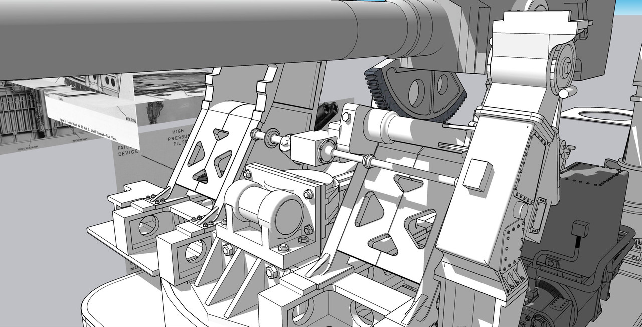
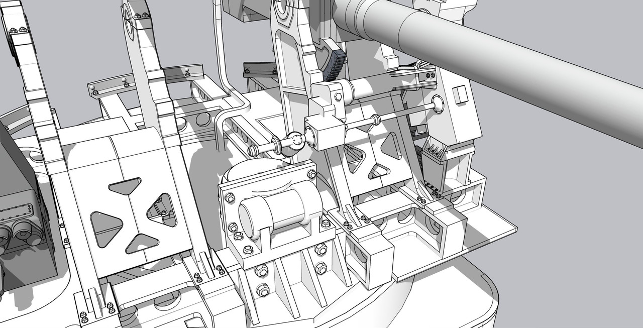
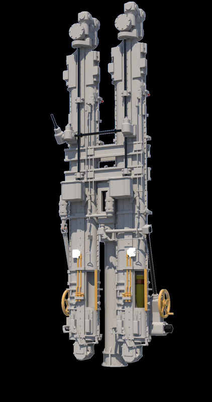
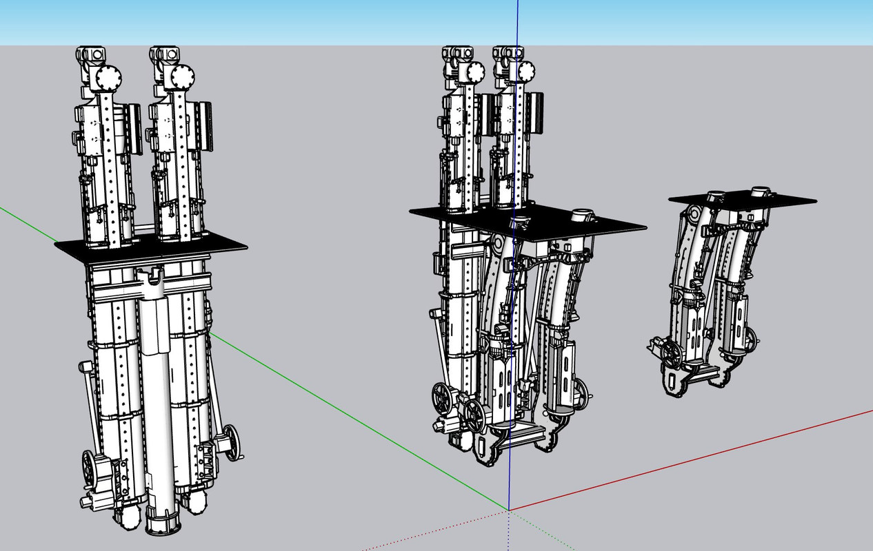
The powder hoist portion was decent, but the control links were too fine being close to scale size. I doubled their thickness, and also increased the floor thickness by 2X to increase its stability and make the diamond plate texture more pronounced.
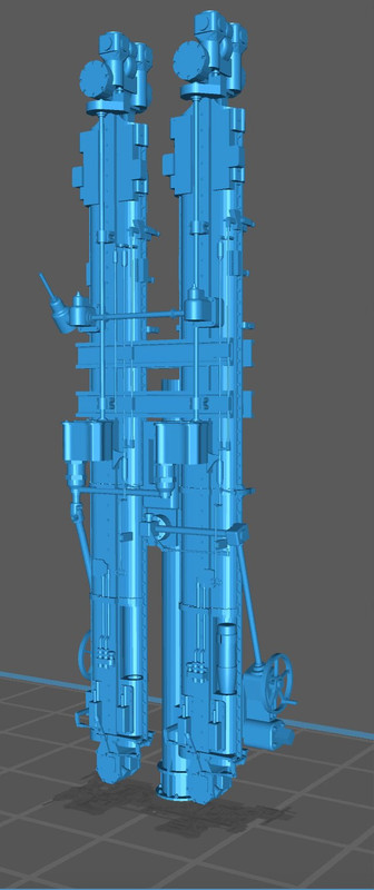
The 2nd projectile print, while correctly sized, needed a lot of repair. I broke one of my cardinal rules: Scale thickness doesn’t always translate well in the 3D printed 1:48 world. I made the columns prototypically hollow with the twin bores extending full length. The resulting wall thickness was so thin that it ruptured all over the place. It was actually translucent. I attempted to rebuild them with Bondic, and while structurally stronger, looked awful.
As with lots of SU projects, fixing is often more difficult than making it right the frist time. And this was no exception. Took about an hour to fill the bores. I also took the time to strengthen some other dubious connections. While doing this I also fixed a lot of drawing stuff like hidden layers that didn’t do anything.
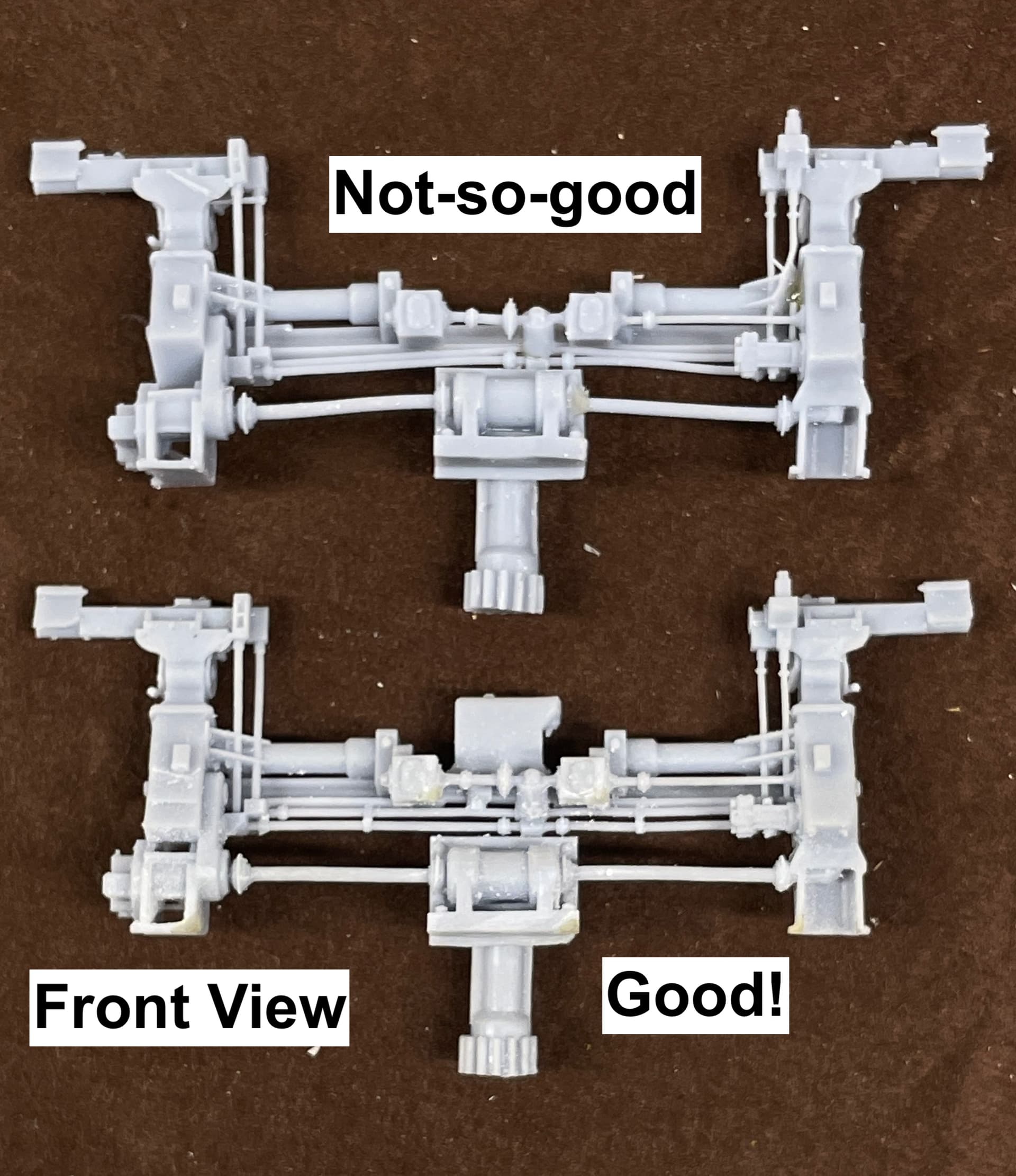
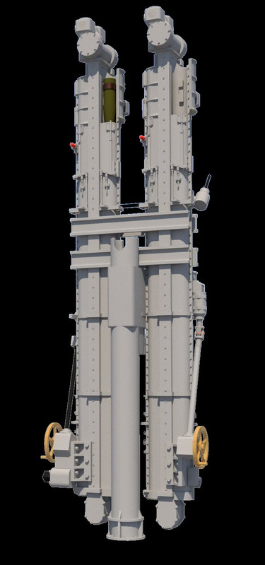
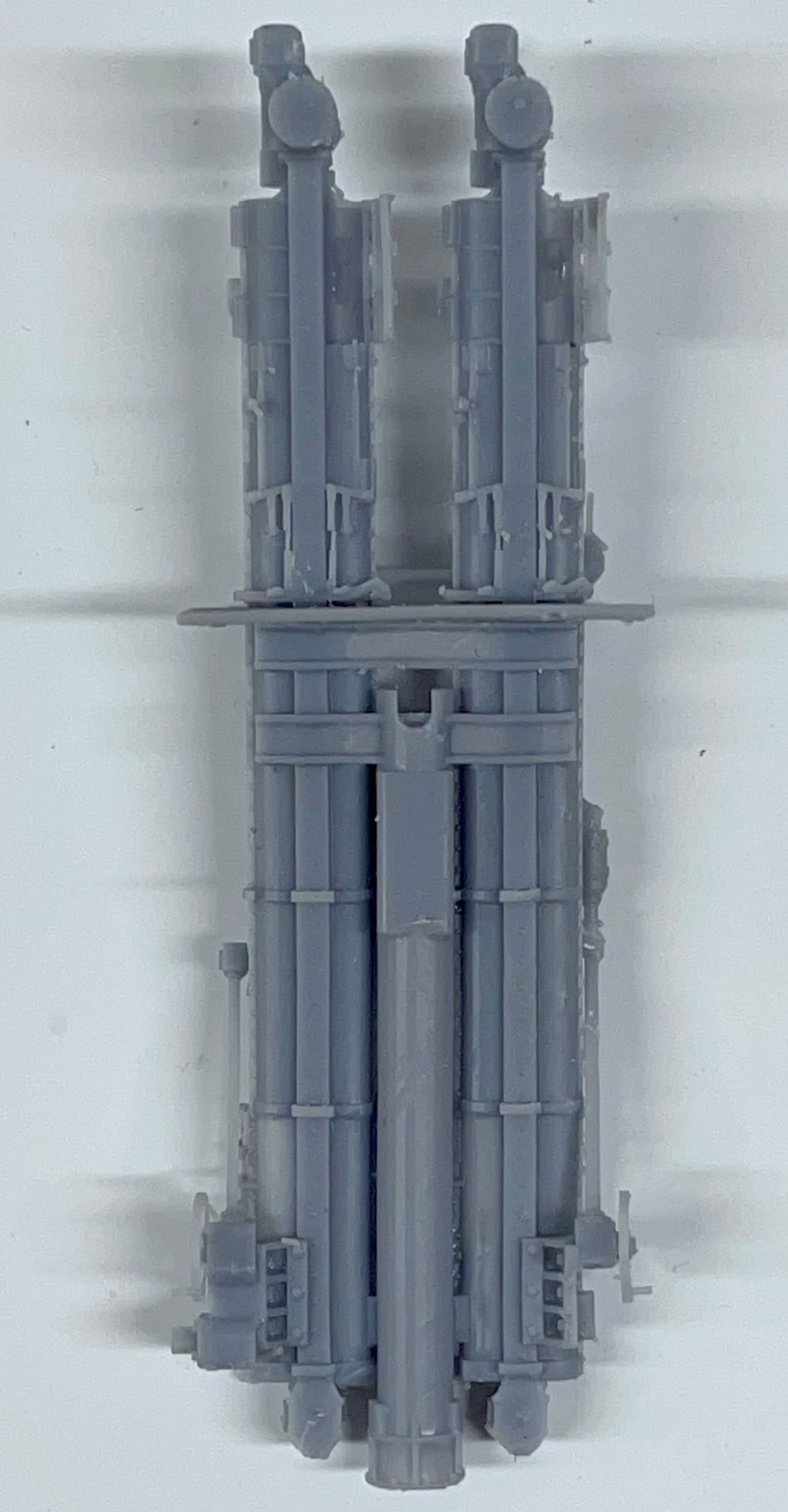
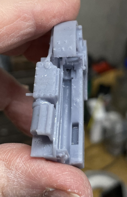
I was rewwarded with a really nice print. I only had to go back and reattached some tiny links and further strengthen the door hinges.
Get a load of those very fine pull handles compared to that #11 blade. I was impressed. I also added some mid-run supports for the long-run link rods so they would have a better chance for printing and after-printing survival.
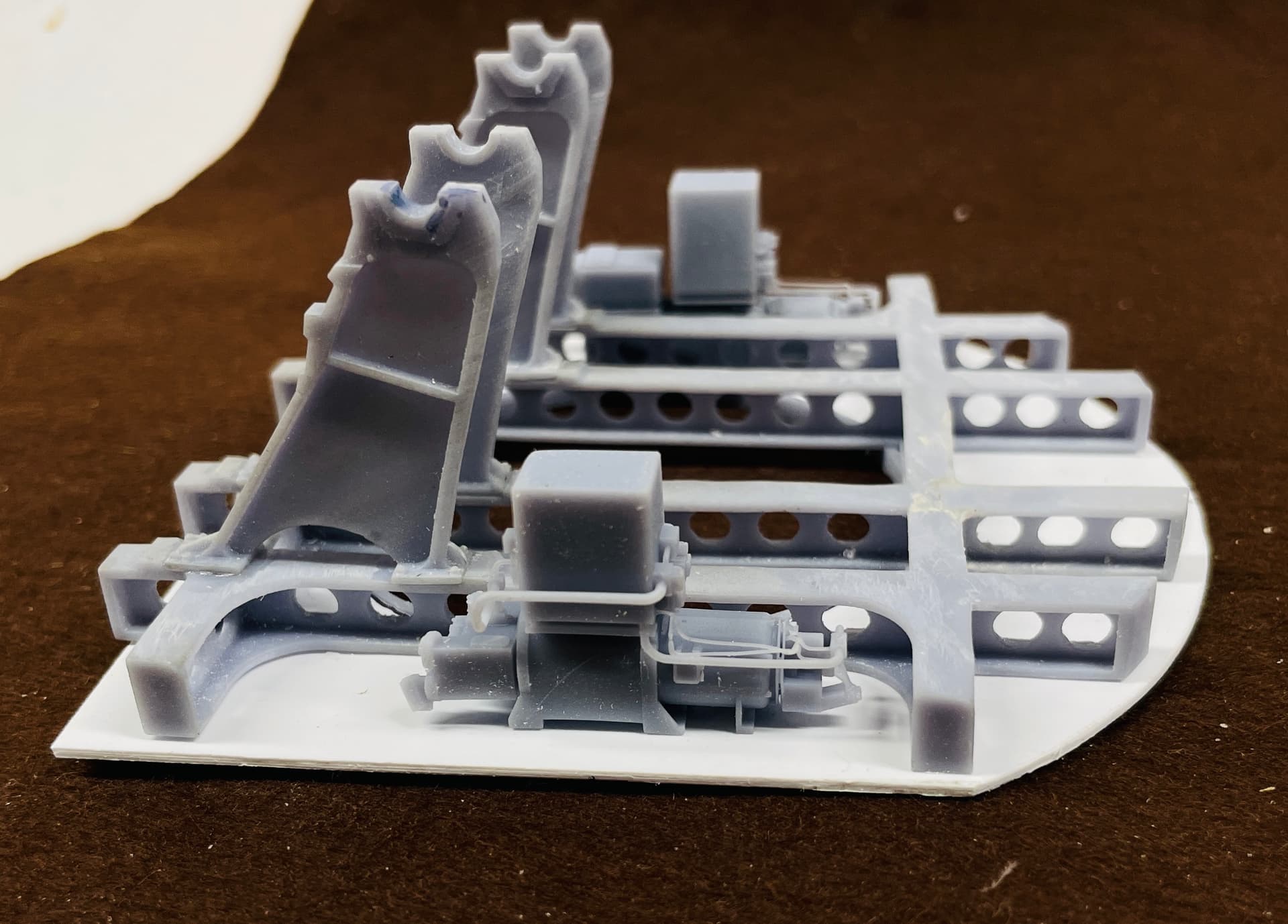
I had to notch the floor at the front corners to nestle over the gun mount’s rear feet. I was worried that after all this work I couldn’t install them, but if I moved the powder hoist as far aft as it would go, carefully inserting the projectile hoist sideways between the frame rails, I was able to lower it and twist it into position. I did have to relieve the width a bit at the cross-girders to make it a slip fit.
This was, without a doubt, the most complex parts I ever produced, and is the apex of complexity on this model. With it successfully done, I can breathe a bit easier.
I drew and printed the floor pans that sit between the frame rails under each gun. These are sheet metal affairs in the real deal, and have a curved floor that follows the arc of the gun. I made perfect prints. Perfect, but for the fact that they were about 5 scale inches too wide! I used the drawing of the frame rails for sizing assuming that my printed part was the same. For some reason, it is not. I will redraw and reprint. They weren’t the only thing that was too wide for the frames rails. The gun itself was too wide to drop down between the rails. More about this later.
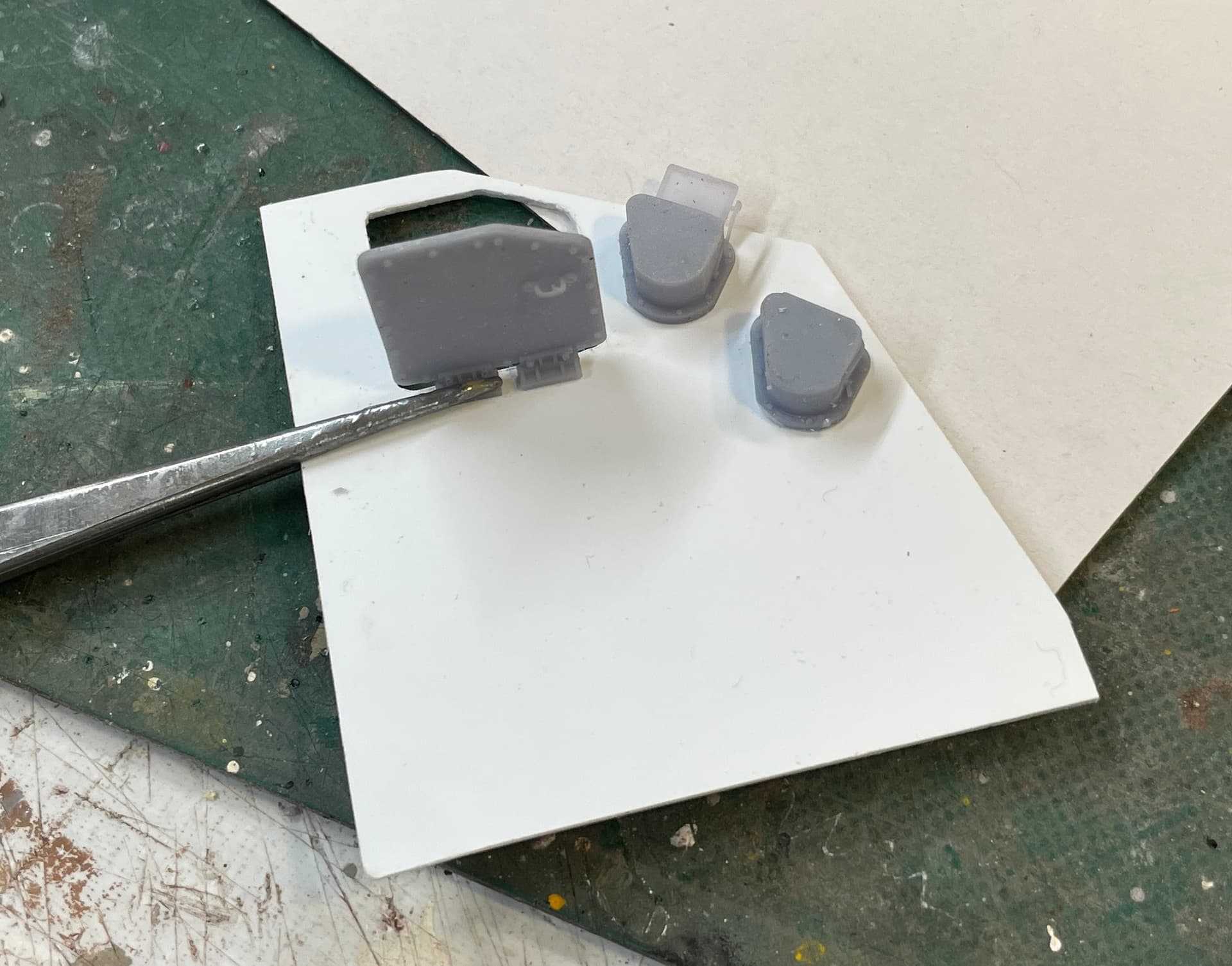
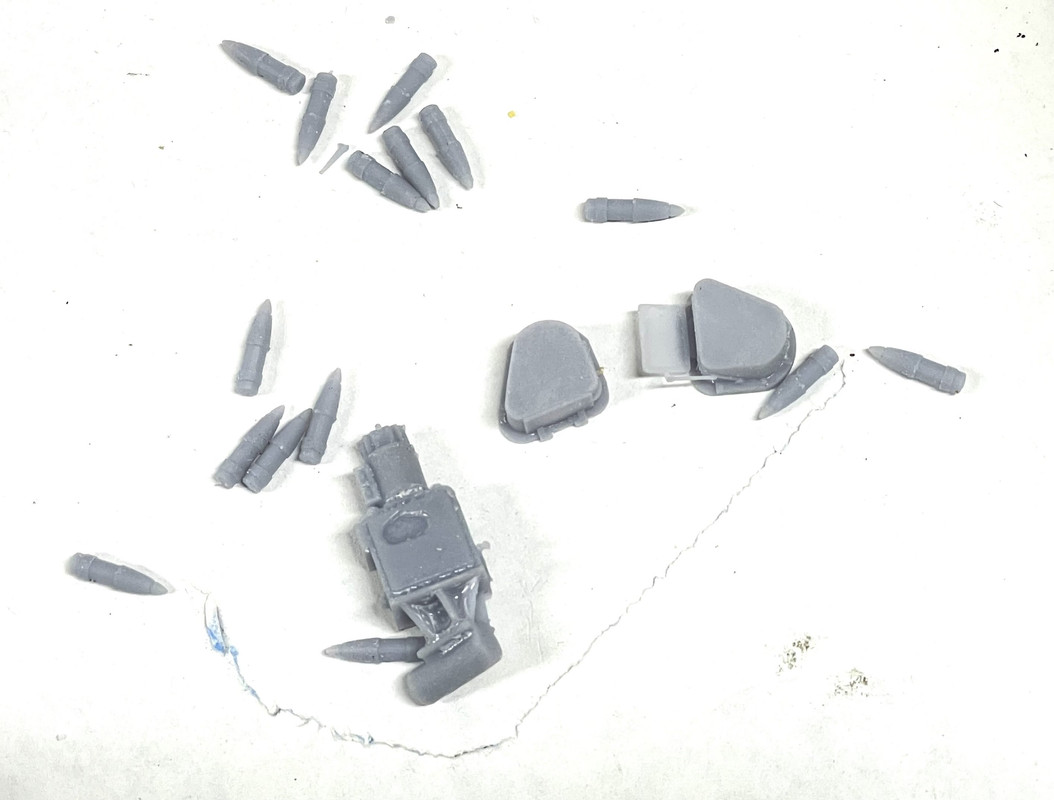
The oil filters and pedestal were easy to draw and print. I drew the tiny hand screws on their caps, not knowing if they’d survive printing and support removal, They did!
I added more stuff and took this image. Starting to get interesting!
About the guns…
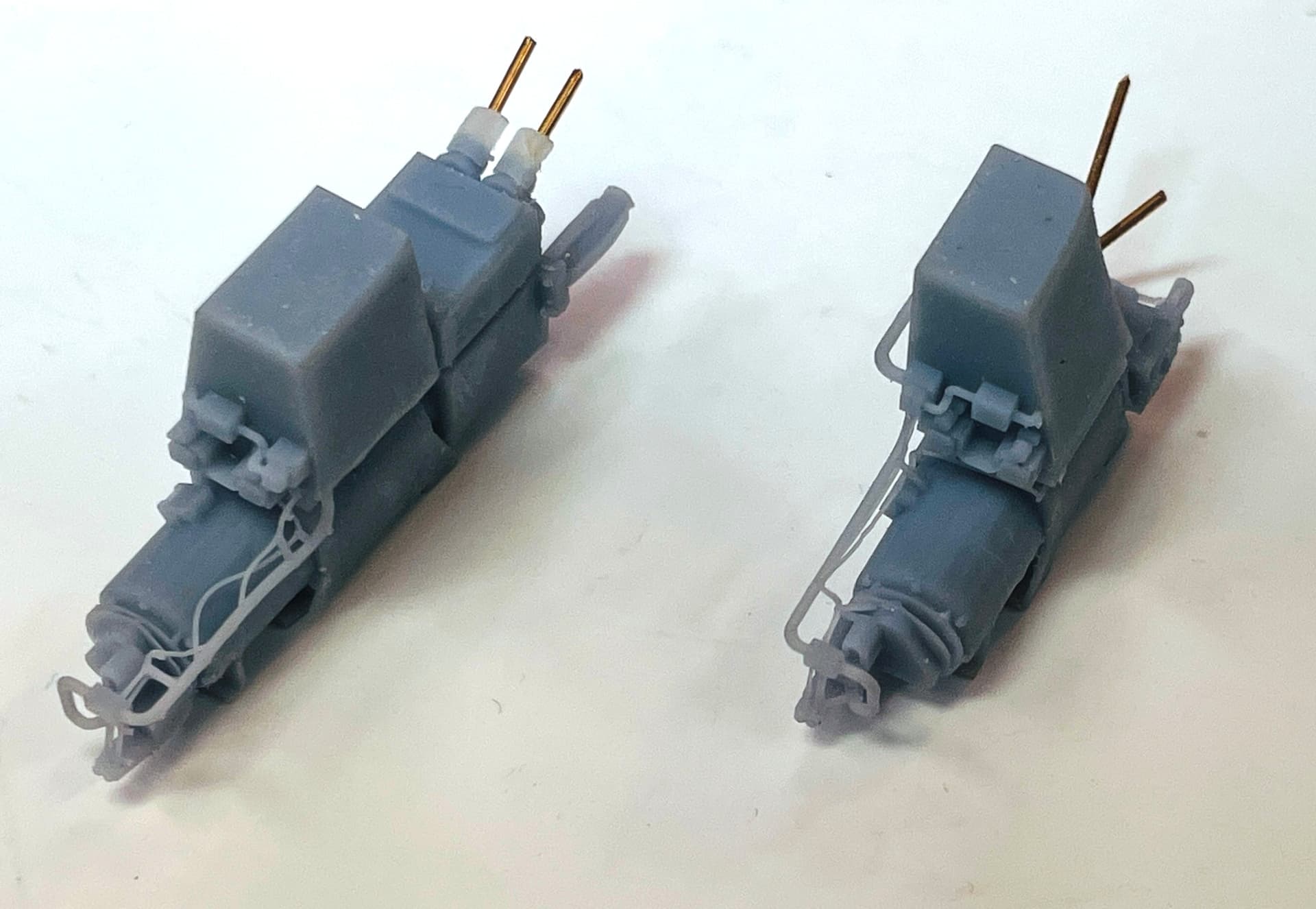
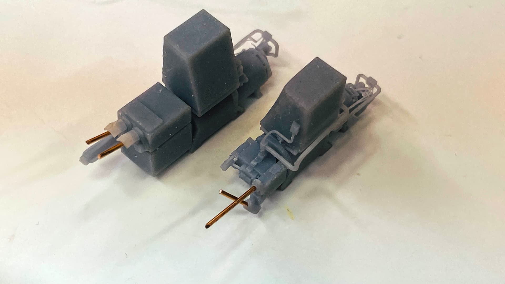
I was unhappy with the prints that I had. The entire trough didn’t print well, and the drawings were a mess with lots of hidden layers and voids that lead to print troubles. With the new print settings I was confident that I could do better. The wrong width gave me an excuse to attack it. Like before, making changes can often be more difficult than starting new, but in this case I did sort of a hybrid attempt using some old and some new. Spent all of yesterday afternoon and more time today to get the internal and external geometry right. I have a lot of time to draw as my wife is recuperating from major breast surgery. She had breast cancer 16 years ago, and it came back. The best of bad news is that it appears to be self-contained. She had full diagnostic scans that were all negative and the surgery went well. So we’re very optmistic.
I’m having a lot of SU crashes. Sometimes it occurs when doing tricky things like using BoolTools2 on big complex interfaces, but others occure just when I’ve made a couple on moves. I never lose too much work since I’m doing auto-backups every minute. But it’s annoying!
For some reason, connecting the straight side walls to that compound curved rear panel drove me nuts. I know how to do it, by intersecting the flat into the curves and removing the intersected parts, but it was a lot harder to do than it should have been. The assembly was built from a bunch of geometries that would cause surfaces to disappear unannounced if I erased the wrong line.
This geometry was the worse part. I’m very happy with how the curved trough is now designed and it should print perfectly. I still have a lot of stuff to add on, but I’m not worried about that.