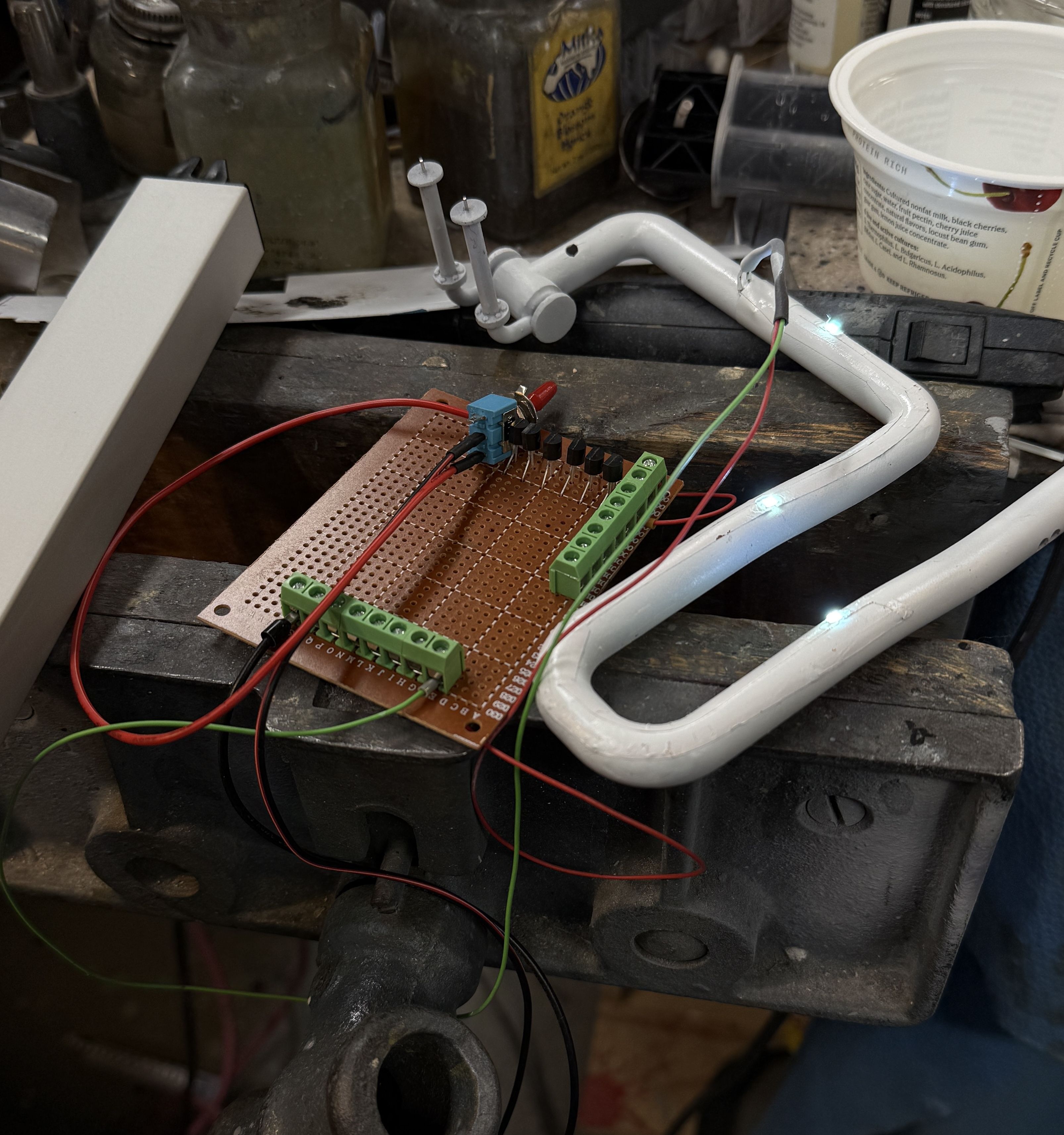
All of the punchlist items up to getting the base from Bryant are done. That means I have a week where nothing’s going to happen on the engine room. Today I did all the decaling and touchup painting. I made the hookups for the power supply and the power switch and tested it with the main steam line which has 3 LEDs on its bottom. There’s nothing left to do until I actually start tying down all the assemblies to the base and that doesn’t happen until the model is secured to the base.
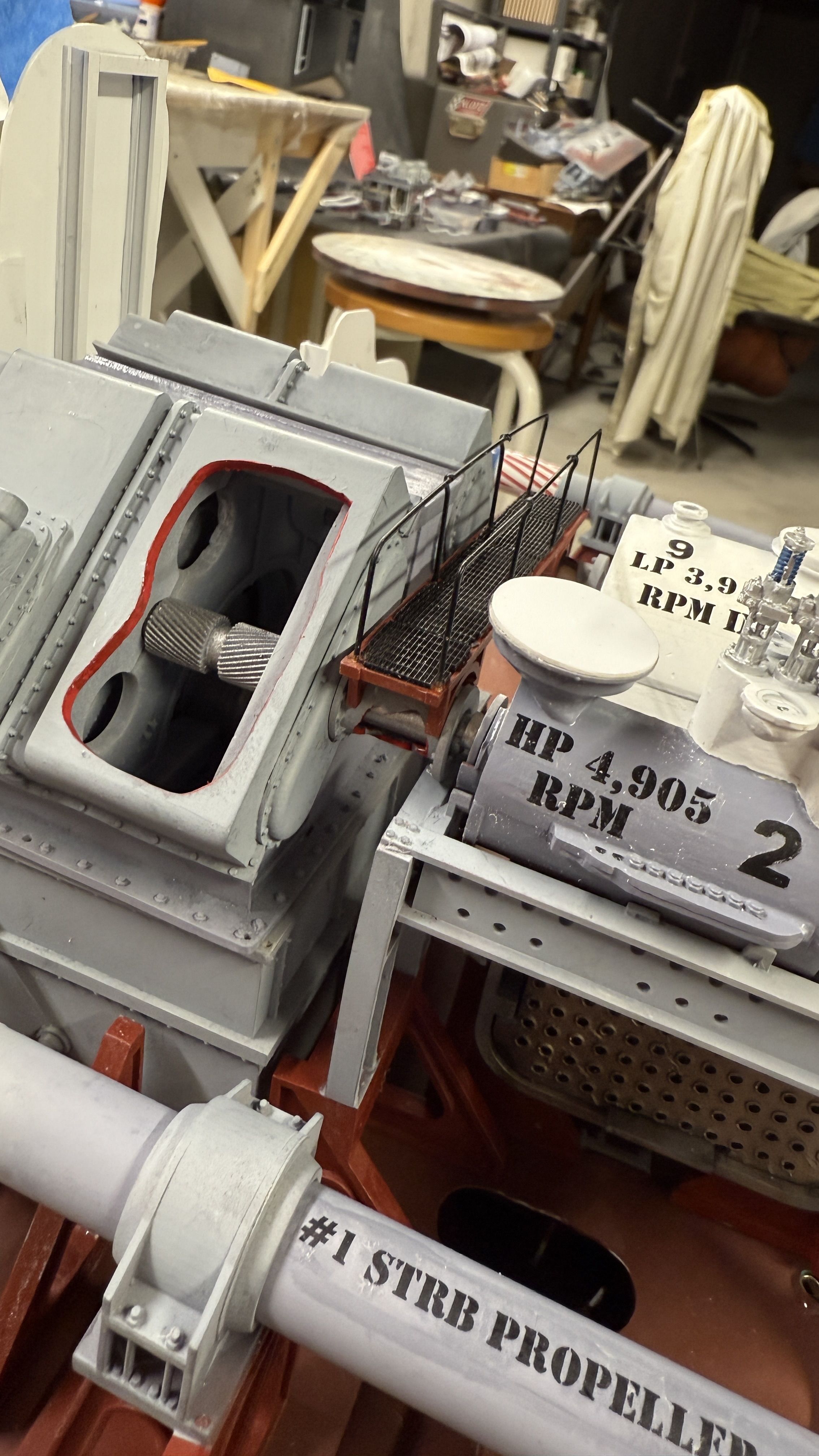
Decals designate the output RPMs of the main propulsion system.
I was unhappy with how the decal looks on the main reduction gear, but don’t know what to do about it. I used flat paint on the gear box and didn’t want to gloss coat it before applying the decal. That was probably a mistake.
I applied decals to the pass-thru prop shafts from ERs 1 & 2.
Again the flat paint was a problem. I applied some Testor’s Dullcoat to them to help blend them in, but it’s still not my best work.
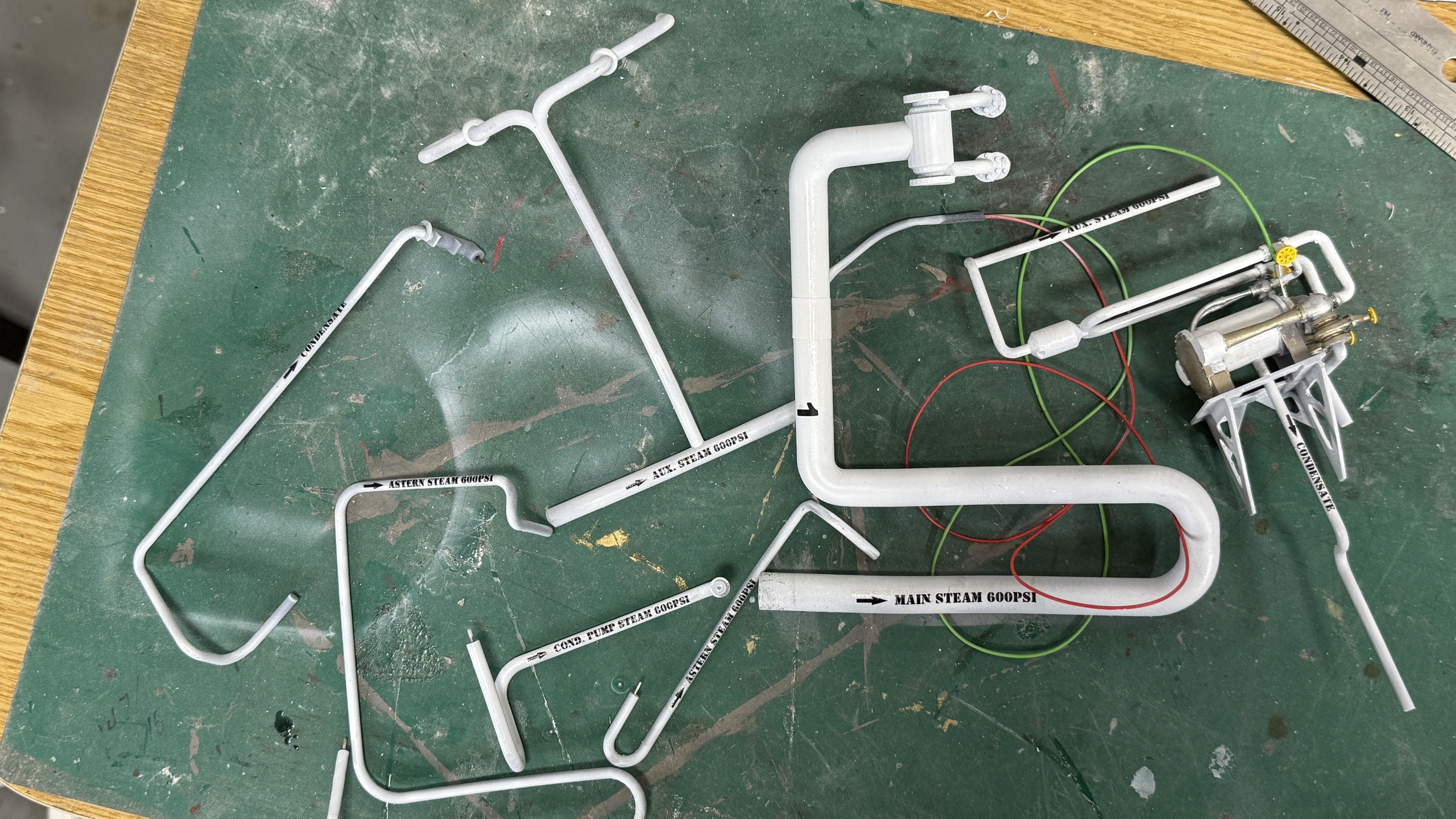
The cross-over pipe is identified with its steam flow pressure and direction.
And all the main pipes to and from the auxiliaries are identified the same way. The piping on the 1:1 ship is also identified similarly, so I’m following the prototype.
And I got the power supply and switch all tied into the power distribution board, so they’re ready for install as soon as the baseboard arrives.
So… work is paused for about a week. I will clean up the shop a bit, and then have some more mundane home maintenance projects. There’s some water areas that are in need of some caulking…
4 Likes
way back in my plane era I think the method was gloss coat then decal then matte varnish on top ?
basically, the gloss varnish would seal the paint and protect it from the decal chemical and all the weathering done, and the matte varnish would seal the whole thing.
(I also remember painting a very thin layer over the transparent parts of the decal, like on your #4 port propeller, top and bottom to blend the limit)
but this dates a bit. 15-20years now
also… you’re a madman  . I admire what you’re doing, it’s quite something !
You are correct and I usually do that. On the white areas I was already using gloss paint. I chose to not gloss the gray for various reasons including not wanting do the entire part and was worried about color shift.
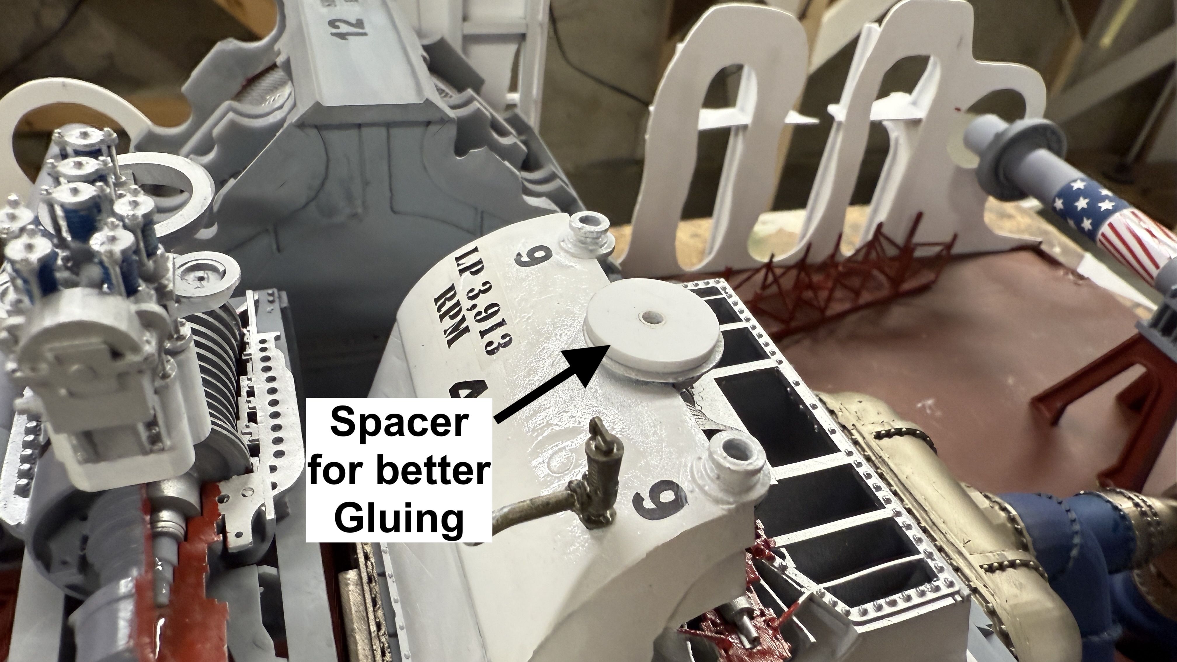
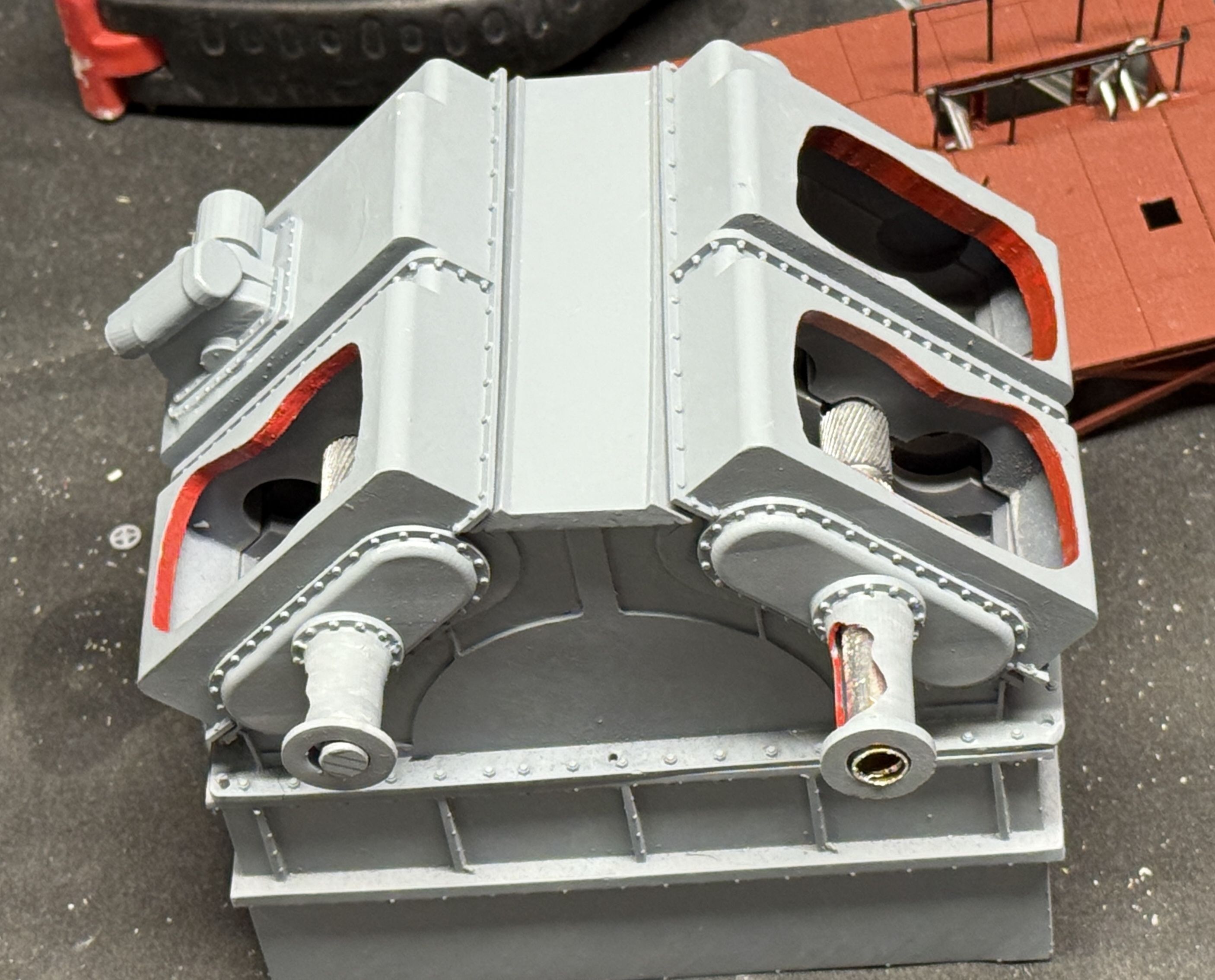
I got a commission 3D printing job which got me back into the shop. I’m still working on some nagging punchlist items. One of these was the mismatch in levels between the two turbines and its effect on the crossover pipe. I also didn’t like the very small surface area I had to glue said pipe in place. To remedy that I made round spacers and fill pieces for the two junctions.
This one is for the LP turbine…
And a broader one for the HP turbibe outlet.
Then a massive problem arrived. The LP turbine was sitting low and needed shimming so it matched the elevation of the main gear box LP inpu shaft. I made the spacer out of laminated styrene (as I used on the LP pipe spacer) and after glue set, shaped the edges so they looked decent. I also needed to further flatten the LP’s bottom surface. This when the trouble hit. Unbeknownst to me, I had voids in the part that contained un-cured resin. I was aware about voids being potential trouble, but when I designed this part early in the project, I inadvertently created some. The wasn’t an issue until I put the turbine on the belt sander an opened up the voids spilling raw resin all over the bottom and up the sides.
I had to remove it using 99% Isopropyl alcohol and it started to eat into the nice repaint job I did last week and made a complete mess of this finished part. I put the part into the post-cure chamber to harder any liquid resin still remaining. The side with the “10s” on it (denoting the location of the astern turbines) and decided to remove the vinyl letters so i could sand down the damage and repaint without worrying about them. I set up the vinyl cutter and just cut some more. Like 3D printing, having the vinyl cutter means I can fix screwups without to much hassle. I then remasked and airbrushed white to restore the turbine. Alls well that ends well and it looks okay. If worse came to worse, I could have reprinted the entire turbine, but wasn’t looking forward to that.
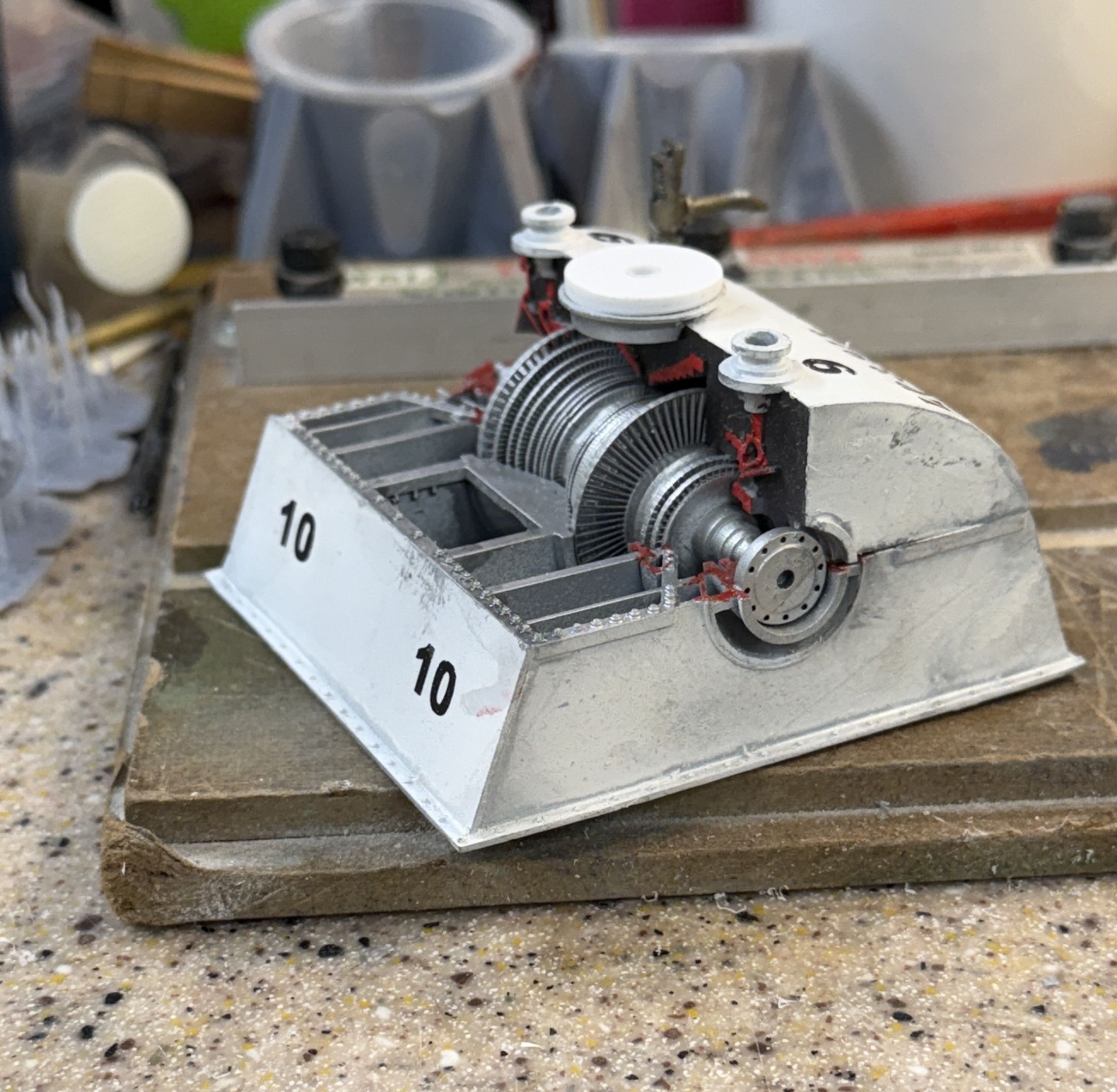
Here’s the spacer…
And the refurbished turbine. I had to remove the LP RPM decal and have extras of that also, and will replace all graphics elements tomorrow.
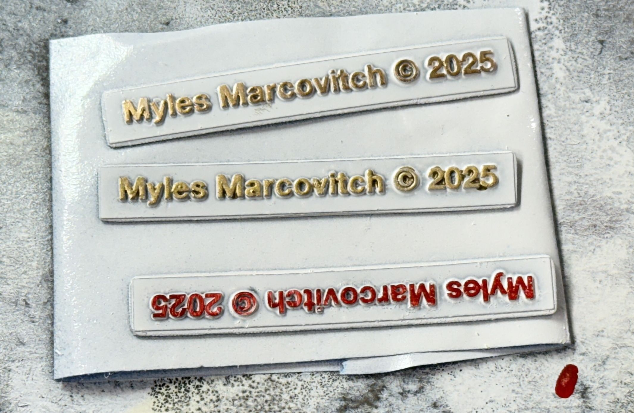
I also printed a copyright plate to be attached directly on the model, not on the name plate. I did them in differnt colors. Any favorites. You can’t see it, but that’s two different shades of gold.
The wooden base is shipped and I’ll recieve it on Monday. Then the real fun begins. I am still anxious about locating all the mounting pins on all the various legs and columns to permanently mount all this stuff.
5 Likes
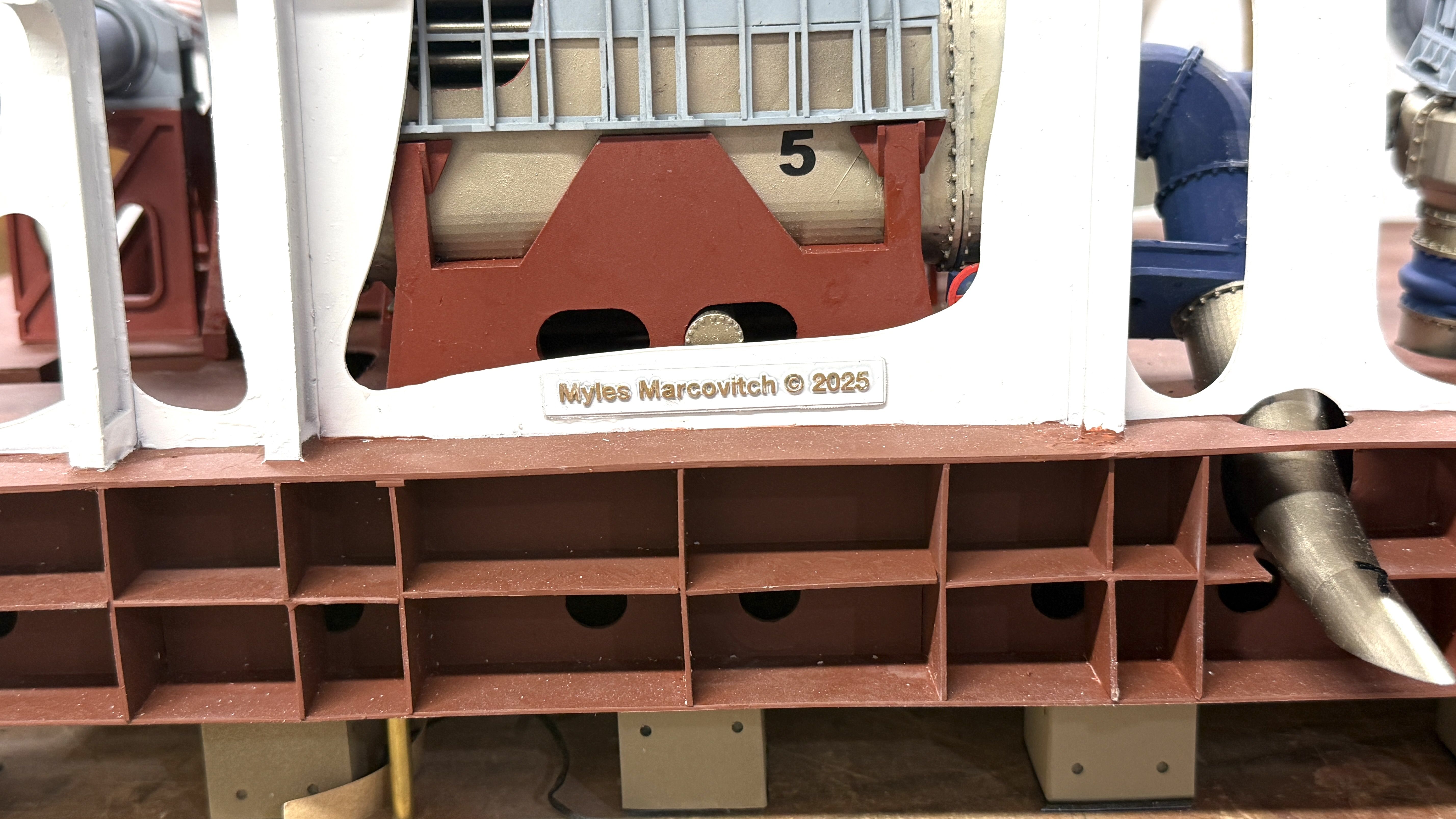
I applied the copyright nameplate to the model with 3m Transfer Tape. I don’t know if it’s legally binding without actually paying for the copyright, but it adds some gravitas to the model.
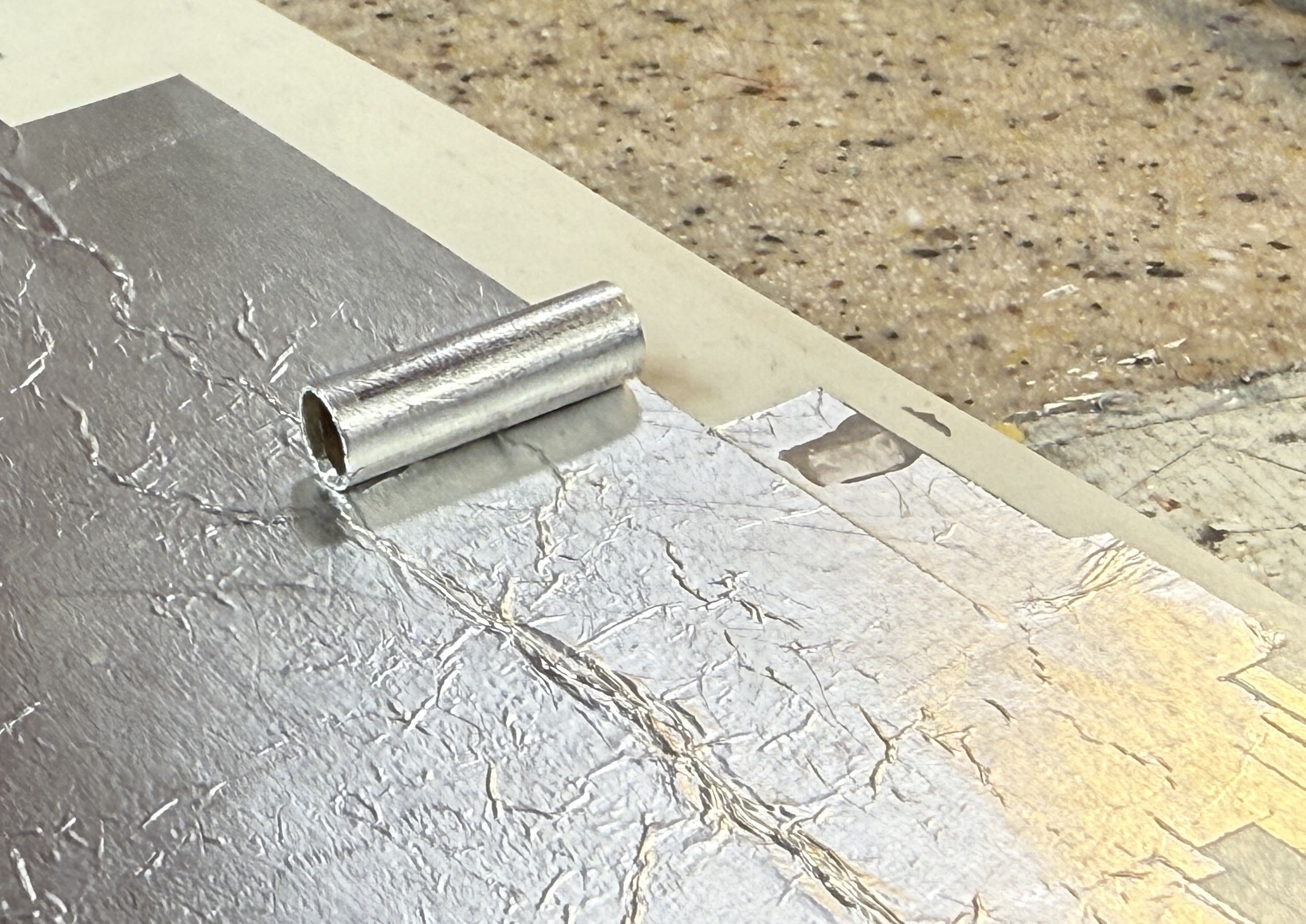
Working on the last punchlist items… I knew that the fit between the turbines and the gear box needed some work and now was the time to do it. One problem was the LP shaft in the gear box was not long enough to reach the turbine, especially now that the turbine is actually almost a half inch more forward that I thought. I had printed a new torque tube to accomodate this, but the shaft needed lengthening. It wouldn’t have mattered, but the tube is cut away so intrepid viewers can see the shafting inside. Instead of fussing trying to add length to the 3D printed pinion shaft, I found a piece of brass tubing that just slipped over. Problem solved. All I had to do was make it look like steel. I used Bare Metal Foil to give it a silver coating. I could have painted it, but this way was cleeaner and faster.
With the shaft now the correct length I was able to finish painting the torque tubes with the red cutaway edges and then epoxy them to the gear box end covers. I’m not going to worry about gluing it to the turbines. The glue surface there is rather skimpy.
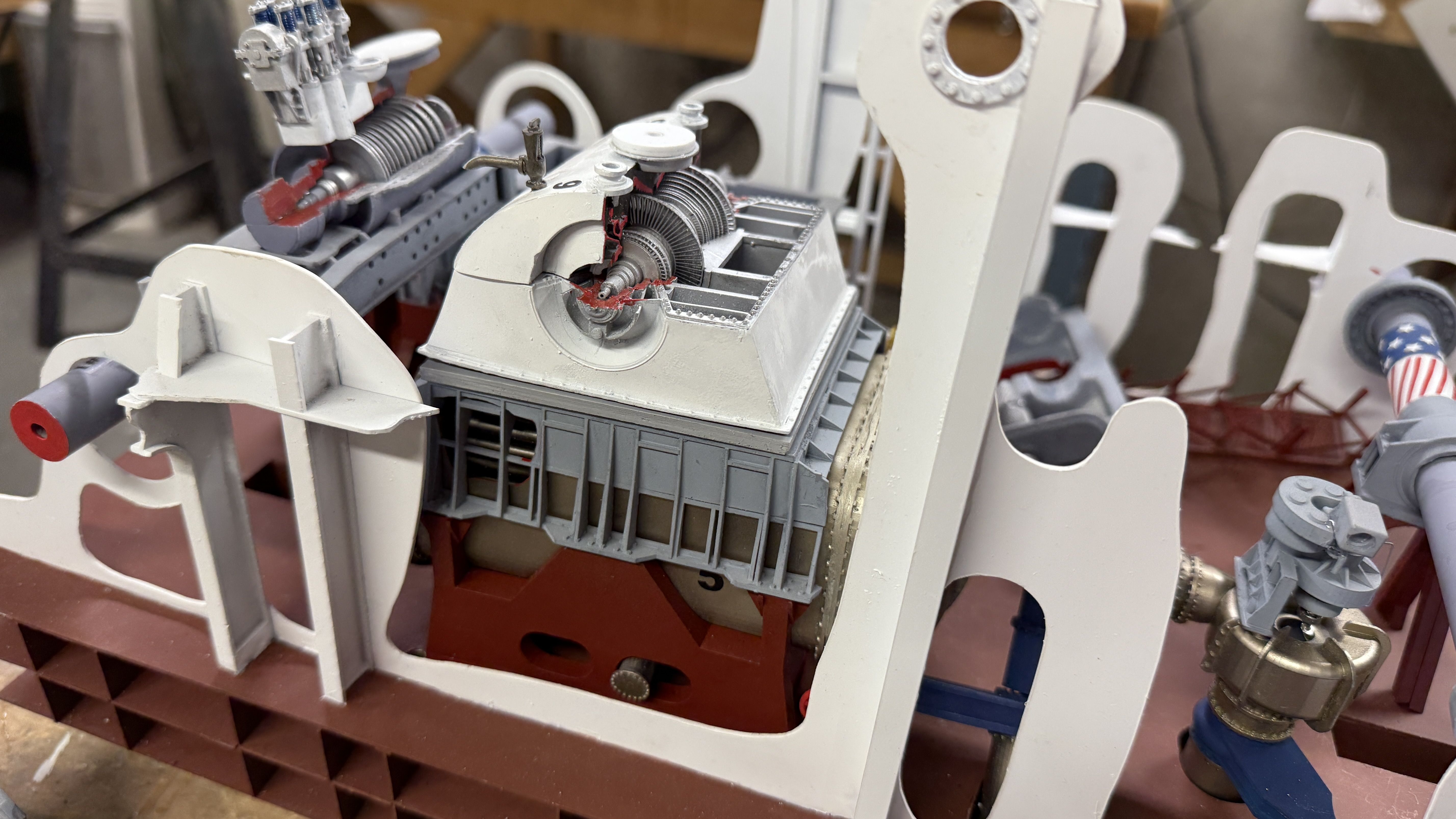
With everything just fitted up for measurement purposes, here’s how the torque tubes look when sitting properly.
I tried the cross-room bridge to see how it aligned and it laid in very nicely. Remember, all of this stuff gets fastened AFTER the bare model is attached to the base.
I also removed the bad decal from the top of the MRG, repainted and applied new numbers and decal. This time, I faced it in the same reading direction as the graphics on the turbines. I had it reversed before and it bugged me. Another thing that’s really bugging me is that the Mission Models Dark Ghost Gray doesn’t match the previous bottle that I used for a lot of the apparatus. It’s leaning towards purple. I can’t seem to match the color gray that I used many months ago. It’s so different that I’m thinking about repainting the rest of the gear box to match. I’m trying these paints, but am not happy. If you don’t add the polymer additive, the paint is very fragile, all pigment and little binder. I’m using Pledge with Future as the acrylic binder. They sell their own additive, but you can get a lot of Future for the same price. I used GlossCoat before applying the decal and then Dullcoat after the decal set and it’s a much better looking job than before.
We went out to dinner tonight and while driving the car I realized that I didn’t add any information about the horsepower output from the turbines. I’m going to add that. Also, according to UPS, the wooden base arrives on Monday. Next week is going to be interesting…
5 Likes
Limited time today, but milestone anyway. First up, I repainted the entire gear box. I will reapply the numbers and decals next session. The paint now meets my expectations.
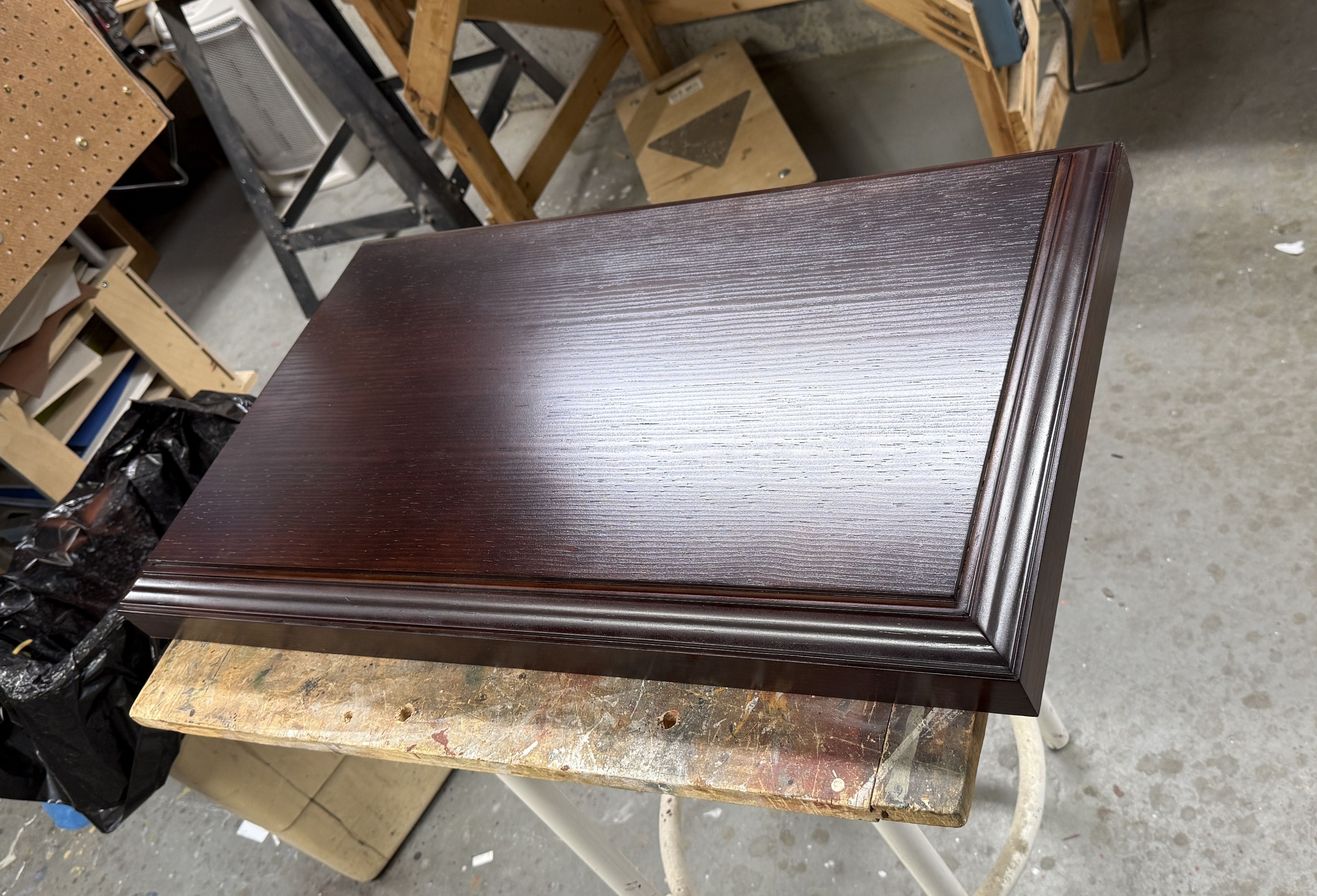
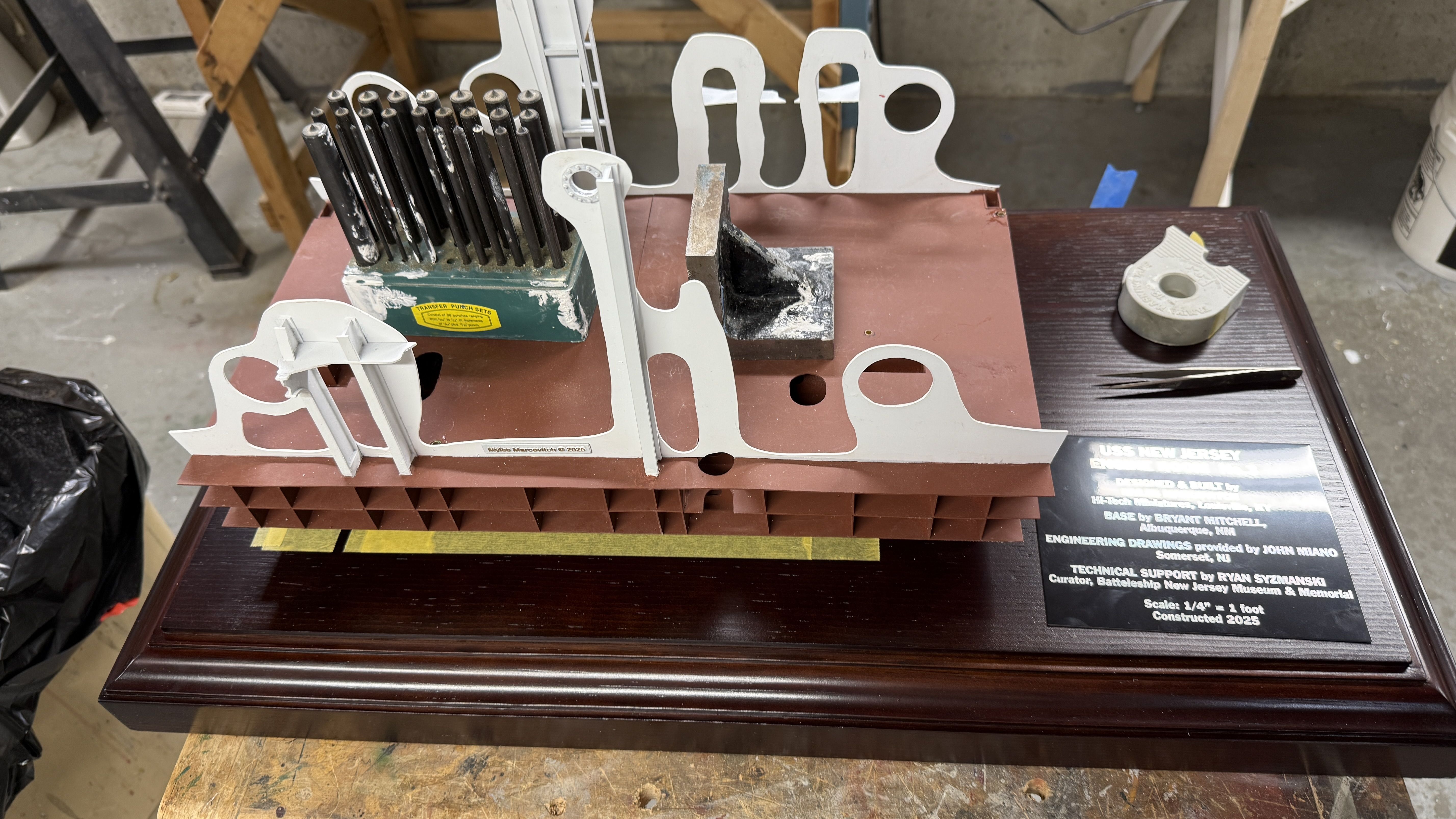
And the milestone is the base arrived perfectly.
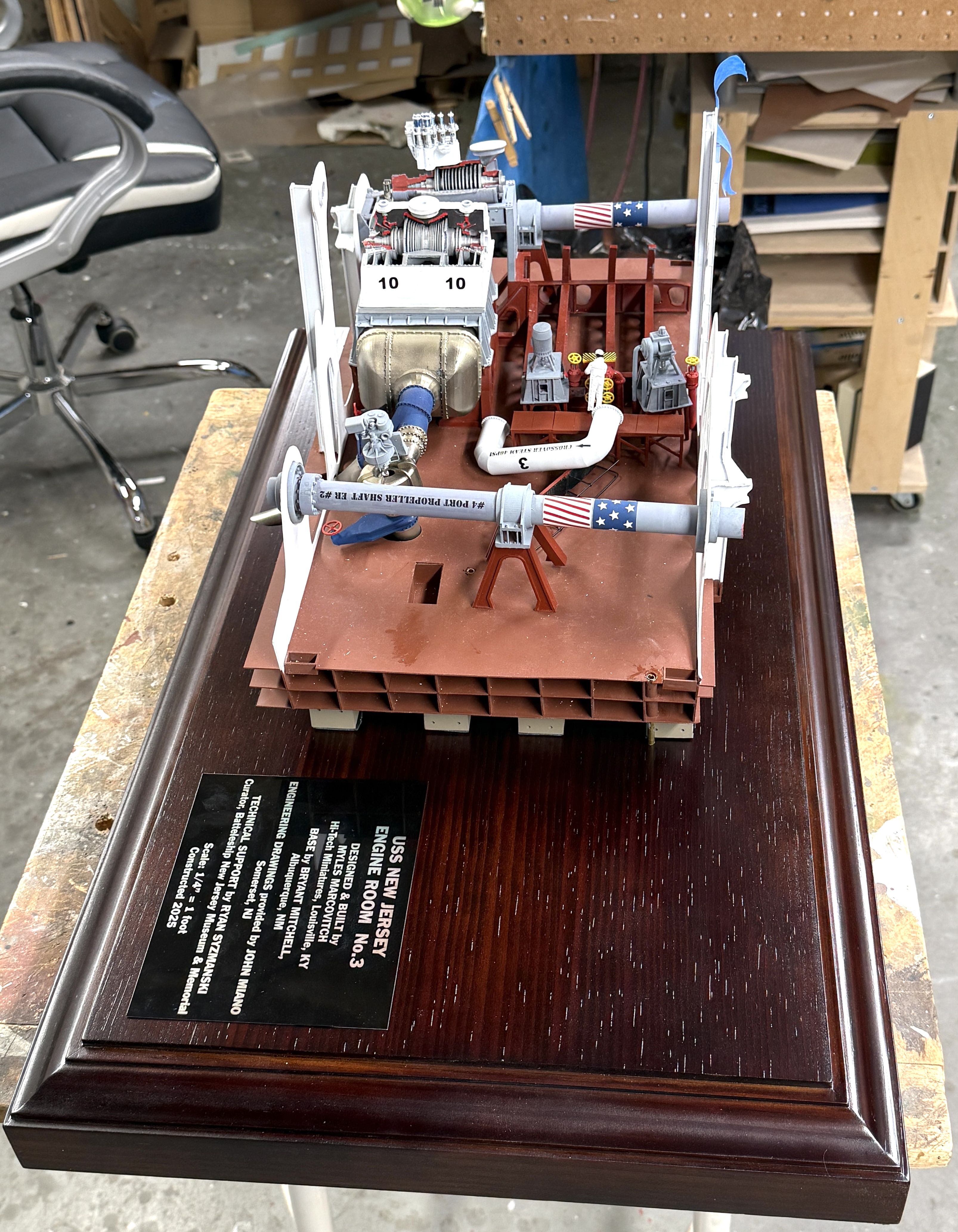
I plopped the model on it just to make sure that all my measurements were correct. Thankfully, everything works!
Tomorrow it the Jewish New Year so I won’t be in the shop, but I will on Wednesday. I will be taking the base to General Rubber and Plastics to have them measure for the plexiglass. When the order is made, I will start the process of making the base and the model ready to be joined. After joining, I will be mounting everything that will make it an engine room. Stay tuned. We are rounding the final turn.
5 Likes
With the base in hand, I took it to General Plastics and Rubber here in Louisville. I’m glad I did. I am getting the plexiglass CNC router cut. This produces a very smooth square edge that requires very little cleanup before glue up. The CNC machine is digital and can work to three decimal places. This enabled me to get the end pieces correctly sized. Reason? The 3/16" plexiglass is actually .177" not .188". They were able to spec the actual measurement of 14.374" to cut the end pieces do they will fit pefectly square within the two long side pieces, letting the top fit exactly over all four sides. If I attempted to do this over the phone, it would not have work. We were able to measure directly from the base.
Even better, the price was $10 less than the material for the 5" gun case and it’s actually a bigger job. I don’t know why this is, but I’m not complaining.
I got the base back to the shop and got to work on it. First up was setting up the model’s location on the base. I eyeballed it and used use a square and masking tape to demark one side and end. I placed some gravity clamps onto the model to hold it in place, and then with a slim transfer punch, located the five lighting lead locations onto the wood surfface.
This image shows the pin pricks where the lighting permitted.
I drilled the holes with an ample brad point drill and then flipped the base over to work on the bottom. I put some felt and cardboard under the base to protect the finish.
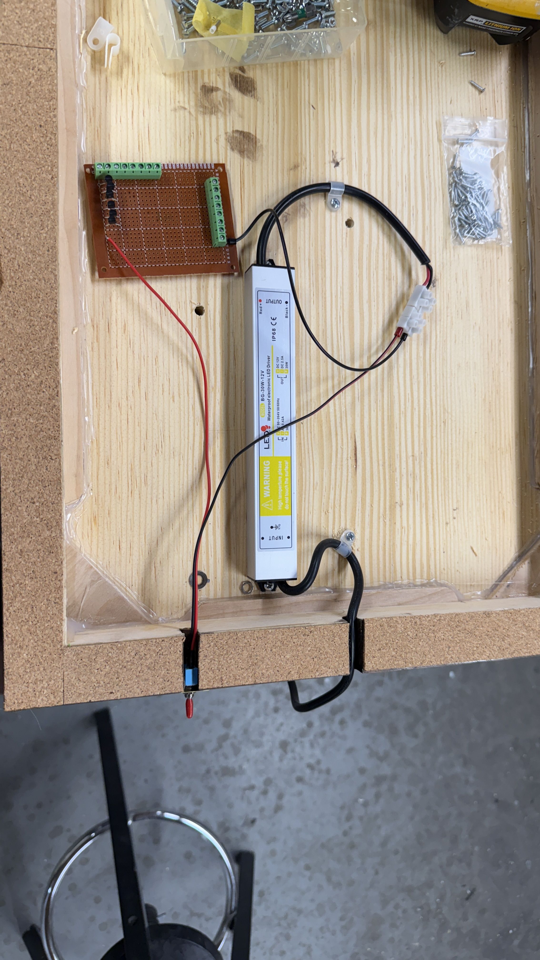
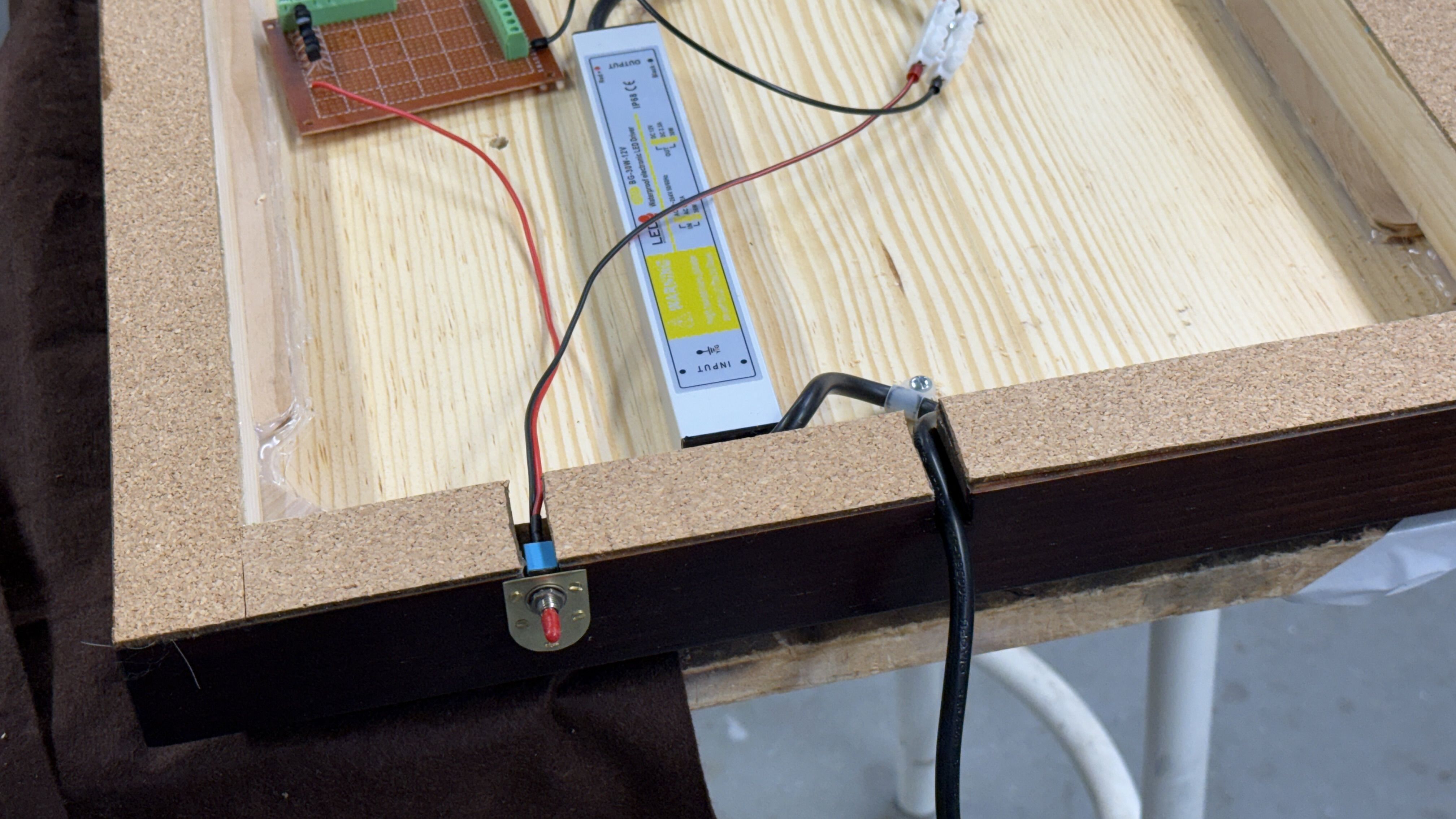
I installed the power supply and secured the power cord with some cable clamps. I drilled some pilot holes for the screws and put some tape to set the drill depth. The main plank is 3/4" thick so I set the drill depth to half of that.
To mount the power switch I crafted a brass mounting plate. I prepared the 15/64" drill for drilling brass and used a clearance drill for the small, flat-head brass screws that would hold the plate and switch in place. I had to do it twice. When I cut the countersink on the thin brass sheet I went too deep and enlarged the opening so far that screw fell through. My 2nd attempt was more successful. I’m preparing all the power circuitry now when there’s no model on top. After the model’s built and plexiglass case is attached, I will lay it over on one side and tie into all the LED wires into the circuit board. It will be the last act before the model is declared complete.
This time I was smart and had Bryant cut all the slots in the base before I got it.
Tomorrow, I’ll mount the circuit board on some plastic standoffs and the bottom will be done for now. Then I’ll flip it back over, remove the backing film on the servo tape, align the model on the tape lines and permently adhere the model to the base… and then the fun will really begin.
3 Likes