There is no reason models can’t be drawn precisely using the method I describe. In fact my models are always drawn with precision of 1/64th of an inch or better.
I use SketchUp Pro but as Box wrote, it doesn’t matter which version of SketchUp was used.
I guess what a really mean is that I’d like precision of dimensions as I’m going, for example so I can track how much of a pre-cut bit of wood I’d have left to work with when trying to layout so as to minimise waste. Is the method mentioned previously in this thread - selecting the edges - my best method for this?
It would be easier to answer if you showed some examples of what you’re after.
I suppose you could add dimensions to the components as you draw. I’d find it annoying to work that way but it could be done. Entity Info will give you the length of a selected edge or edges. That could be useful but if the edge selected doesn’t represent the overall length of the part, it won’t be very precise. You could draw a rectangle to represent the stock and overlay the parts on it.
It sounds as if you’re letting the size of the bits of wood you have determine the dimensions of the project. Is that correct?
After a hiatus I’m back looking to use SU for some woodworking projects.
Starting a new Woodwork Template Project in mm, and I’m hitting a snag right away.
For example I’m looking to model a piece of wood which is 21mm x 90mm x 910mm.
Should be super simple right? Create a Plane and Extrude to length!
I select Shapes > Rectangle (R) to create the end face. I try to draw out exactly 21mm x 90mm by eye but that’s impossible. So instead I then just start typing 21and hit Enter, then I type 90 and hit Enter.
A plane is created. Great.
The problem is that when I look at the Entity info the dimensions are always wrong.
For example I just followed the above and the resulting plane had edge dimensions of 36.96mm x 90mm
Questions:
How do I create a Plane which is 21mm x 90mm (as an example)?
How do I rectify this ‘mistake’ and resize this 36.96mm x 90mm Entity/Plane to exactly 21mm x 90mm?
I’m sure I’m missing something however none of the above answers these very basic questions!
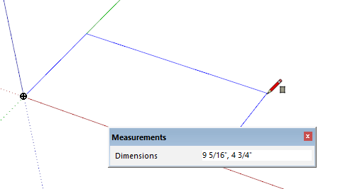
This is just plain the wrong way to enter the dimensions. If you use a comma as a decimal separator, type 21;90 and hit Enter after starting the rectangle. If you use a period as the decimal separator, type 21,90. Start dragging out a rectangle and look at how its dimensions are displayed in the Measurements window. Type your dimensions the same way. If your template is set to mm, you can omit the units.
To resize a rectangle after you’ve drawn it, you can select an edge and move it with the Move tool. In this case it’s easier to start over.
By the way, if you use the Line tool, you can enter one dimension at a time but then you are only drawing one edge at a time.
Thanks Dave, that works. Not the most intuitive, but it works.
I now have another issue, not sure if I should start a new thread but I’ve created two 21mm x 90mm x 910mm Entities (two wooden beams)
How do I align them in the 3D space?
Let’s say for the sake of simplicity I just want the short end of one Entity perpendicularly aligned at the end of the other Entity. Think an L shape, the most basic 90 joint in the world!!
How do I move the Entities so that (for example) the touching vertices at the exterior/top of the joint are both at 0x,0y,0z?
I’ve tried Moving one Entity however the Snap-to functionality doesn’t seem to work - it always just intersects or leaves a .5mm gap.
First make sure you’ve made a component or group of each beam. Then grab the one you are moving at a corner that will be coincident with a point on the other beam and move the points together.
To be honest, if you are drawing your parts and moving them around to assemble the model, you’re working too hard. It’s a heckuva lot easier to draw the parts in place. Draw the first one where you want it, make it a component and then start drawing the next one. You can use what you’ve drawn as a reference for the next thing you’ll draw.
You can move the point you grab to 0,0,0 by starting the move and typing [0,0,0] but figuring out the coordinates for each part is way too much work.
I am trying to make brackets etc. for 3D printers, most objects I encounter are rectangles, circles and triangles - I am curios - why are triangles not included in the drop down list of shapes?
I guess it’s because they are so easy to make with the line tool, and a triangle tool would need to have a variety of types to be of any practical use…
i am having a similar issue. i have a project i am working on and trying to modify the measurements after creating a rough mockup of a component i want to do a test print to verify everything fits properly (3d printing parts). I thought i had it figured out by using the dimension tool. I selected the endpoints on an edge for a plane and it showed the measurement, i double clicked on the measurement that was shown and entered in the value i wanted. It took this and i thought it had resized my object accordingly as it was really close to begin with but when i did that for another side that was not close to the proper dimension it let me enter in the measurement i wanted but didnt change the size at all. so i am not sure what if anything the manually entered dimension values mean.
Do not think that changing a Dimension entity changes an associated Edge [Line] length.
If you have an ‘unbounded’ edge you can change its length by editing it in Entity Info.
Otherwise, you’ll need to use some other methods - probably guide-lines or at least inferences - to Move [tool] either edges or their vertices to the new positions you desire [or even Scale, PushPull etc].
Any associated dimensions should adjust accordingly - but they only show the current length - they do not change it…
If you edit the text of a Dimension, that is all you have done - changed the text. It has no effect on the object’s size. You need to use the scale tool or else edit the component and move edges, pushpull faces, or the like to alter the size.
This may sound a bit odd, but if you’re new to SketchUp stick with it.
The generic way most CAD systems do things seem to be at odds with SketchUp, but stick with it and you’ll find it much more rewarding than most after the steep and frustrating initial part of the learning curve.
I want to change the length of an existing pipe.
s
I drew a hollow cylinder (ok, a pipe), very simple to do. How/where do I type in the actual length I want the cylinder to be? “Scale” command just works in % and isn’t what I am looking for. Pull does two things, neither help: 1) if I pull one end of the cylinder, it tells me how much I am changing the current length, not the actual length of the cylinder (you should be able to hold down the shift, alt, or ctrl key to change this mode to show/edit the full length) 2) I added a visible Dimension to the length of the pipe, and it does, indeed, show the overall, changing length of the pipe as I drag the surface - but doesn’t allow me to get precisely a 100mm length, say.
This only works for me with metric units. I try to enter 32.5in and it doesn’t recognize the ‘i’ and just gives me 32.5n which of course is meaningless.