I am a novice who has watched the excellent Intro videos. For my first project, I am trying to model the various pieces of wooden train track (generic for “Thomas”) that I have so my grandsons and I can do a full design of the new layout that they want.
I have been successful in measuring the actual dimensions of the various pieces and creating straight sections that match the real one closely. I first created a 2 D cross section of the track, drew a line perpendicular to it from one edge, and then used FollowMe to extrude the cross section the length of the line. It turned out exactly as I wanted. I was also able to create the interlocking tab and cutouts and combine the sections to form components of the various straight parts. So far, so good with only a little time invested. I very much appreciate the power of SketchUp Make.
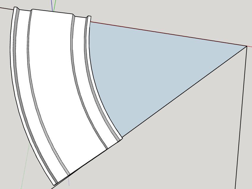
My problem is in trying to create curved parts. The real parts have ends that are at 45 degrees to each other, so 8 pieces form a complete circle. I have been able to create the outline of the curve in 2D perpendicular to the cross section, but when I try to do the FollowMe, the ends do not come to 45 degrees. I believe because the cross section is pulled at a right angle with the line to be followed, so regardless of whether you use the centerline arc, the inside arc, or the outside arc, the “face” of the end is skewed to the desired line.
The lines of the “pie section” form a 45 degree angle ending at the outer arc. The two ends are not lined up with the 45 degree lines.
This would be okay if I could trim off the excess, but everything that I have tried leaves a “hollow” end.
Any suggestions of a better way to approach this would be greatly appreciated. TW_3_Inch_Curve.skp (104.3 KB)
Respectfully,
Tom
I did try that, and what happens is that the ends still are not even with the 45 degree lines. The inside is still too long, but not as much and the outside is too short. I think that for what I want to accomplish overall in doing the layout for the entire track, it will probably be an acceptable error. But the engineer in me keeps thinking that there should be a way to make it exact. So before giving up, I thought that I would ask the community.
Here is before the FollowMe instruction on the center line…
Note the slight difference between the ends and the 45 degree lines back to the center.
I realize that the ultimate solution may be to upgrade to the Pro version and use the solid functions. However, since this is for a hobby and I am nearing retirement, the budget (and my bride of 43 years) won’t let me take that approach.
One thought that just occurred to me is that there may be a default value for how fine of arc the curve tries to follow. If the default is 1 degree, then changing that to 0.5 or 0.25 may bring the ends more in line. If anyone knows if that is something that can be modified, please let me know.
Curves are made of segments not true curves. Follow me will finish perpendicular to the end segments.
Easiest way is to start with a circle follow me and chop out the section you need.
Box, please forgive my ignorance, but how do I chop out the section that I want? I was able to FollowMe of a circle through the center of the ross section.The result is this:
FWIW, Your second screen shot showing the ends of the track not aligned with the radial lines indicates that the end segments are not perpendicular to the radials. If the profile is not placed perpendicular to the first segment in the path, the Follow Me tool projects (not rotate) it to perpendicular. And the extrusion will end perpendicular to the last segment in the path. If you use a sector of a circle instead of starting with an arc, you can end up with what you want.
I created the arc for the path by starting with a circle and rotating it so an edge crosses the red axis at 90°. Then I drew radials along the red axis and at 45° to the red. When you draw the initial circle, make sure you set the number of sides to a multiple of 4 so that both the last segment in the path will be oriented correctly.
The midpoint approach jimhami42 recommended is what I used for years and it works quite nicely.
However I was later told that when representing curves by straight segments the convention is to have the vertices on the “actual” curve, not the midpoints on the curve. This probably doesn’t matter unless you are planning to take measurements from the model.
The approach I’ve started using myself is to use Follow Me along a longer curve than the desired output and then crop it.
Julia, that is correct if the profile is placed in on the path as in your example. If you set it up as I did, that isn’t a problem. The profile is placed at the correct radius from the center of the arc. This way it doesn’t matter what the arc path’s radius is.
I looked up the radius of Brio wooden track curves and found inner radius of 182 and outer of 222. I drew the profile based on those radii and they are still correct after Follow Me.
Thanks for the prompt reply and very informative video. I understand the approach and will try it this evening. I have a feeling it will be a long night.
Thanks also to you for the help. I really appreciate learning different approaches to problems, as each has advantages that can be useful. I also appreciate the prompt response. I am not accustomed to this level of support on a forum.
DaveR,
Thanks also for the detailed explanations. I will try working through them this evening.
I don’t understand your direction to “make sure you set the number of sides to a multiple of 4 so that both the last segment in the path will be oriented correctly.” How do you set the number of sides? What is a side of a circle? Being a novice to SketchUp, I’m still unfamiliar with some of the terms. If you have recommendations for training I would appreciate them. There are so many references I’m not sure where to start.
I appreciate your time in looking up the Brio info. I purchased some track from ChooChooTrack.com after meeting the owner at a train show. He makes his own track and has a slightly different cross section than some of the competition which allows the trains to track better. Also, all of his sections are in even inch lengths, which helps with layouts for me.
Again, many thanks for your time and help. I am in awe of you pros willing to share with us amateurs.
In SketchUp, circles and arcs are approximated with a series of straight line segments. You can see those in the screenshots through this thread. When you first select an Arc tool or the Circle tool, you’ll see the number of segments or sides that will be used. If you type a new number and hit Enter, SketchUp will use that new value.
The reason for choosing a multiple of 4 with the method I described is so the half-segment at each end of the arc is perpendicular to the radial line in intersects with. Hopefully you can see that in my first post.
As for the dimensions I used, that was mostly to show that you can easily create the correct radius curves by placing the profile at that radius from the center of the arc and the arc’s radius is really not critical.
Thanks!. I found the sides after reading your explanation. Being new to SketchUp, I didn’t notice it in the input box before because I always plopped down the center point first, then looked at the box to check the radius. I can see that I need to slow down a little and pay attention to the entire screen.
My only previous experience with CAD was AutoCAD Electrical for control wiring diagrams, so drawing 2 D and 3 D, plus learning a different GUI has been a challenge for an old guy. But it is so well designed that I am gaining progress fast.
I believe I know have a clear understanding of the concepts that I need to finish the designs.
Thanks to the three of you for your help. I will try to minimize future requests.