That was fast service. Thanks, so much.
1 Like
Version 2.2.8 - 08.04.2021
- Fixed a bug with blocking and insulation for portal frame garage doors within rectangular walls.

Portal frames add a good deal of complexity to the framing, blocking and insulation. Some of the details were not completely worked out previously. I think I now have most if not all of these issues addressed.
I also may need to spend some additional time on the holdown placement when multiple portal frames are adjacent to each other like in the example shown.
mdkBIM Tutorial 1: Modeling a Two Car Detached Garage (41:14 min.)

A few issues popped out during the making of this tutorial:
1.) Portal frame holdown placement, custom deletion and redundancy, feedback required.
2.) Wall copy tool did not copy the insulation option setting.
3.) The insulation algorithm seems inconsistent when dealing with tee intersections.
View garage model here:
P.S. I just re-watched the video and there is no bug with the wall copy tool, I just checked the wrong box for the insulation.
Version 2.2.9 - 08.06.2021
- Fixed a bug with framing, blocking and insulation for tee intersections for all wall types.
- Fixed a minor bug with six panel doors when the door vertical offset is a non-zero value.

This resolves the issue #3 noted in the recent mdkBIM tutorial. I would highly recommend installing this latest update.
1 Like
Version 2.3.0 - 08.08.2021
- Fixed a bug with wall presets for rectangular walls.
!!! CRITICAL BUG FIX !!!
If you are using wall presets with rectangular walls and have upgraded to Version 2.2.4 or later then you will want to upgrade to this latest version which rectifies a bug introduced in Version 2.2.4.
Version 2.3.1 - 08.09.2021
- Added a vertical offset parameter for cladding material for gable walls.
- Added a vertical offset parameter for “Log” and “Shiplap” cladding materials for gable walls.
- Added a horizontal offset parameter for cladding material for gable walls.
- Added a horizontal offset parameter for “Board and Batten” and “Metal” 3D cladding materials for gable walls.
Version 2.3.2 - 08.12.2021
- Added a vertical offset parameter for cladding material for shed and hip walls.
- Added a vertical offset parameter for “Log” and “Shiplap” cladding materials for shed and hip walls.
- Added a horizontal offset parameter for cladding material for shed and hip walls.
- Added a horizontal offset parameter for “Board and Batten” and “Metal” 3D cladding materials for shed and hip walls.
Some rather tedious code updates but important that these wall types have all the options of the rectangular wall type.
Version 2.3.3 - 08.17.2021
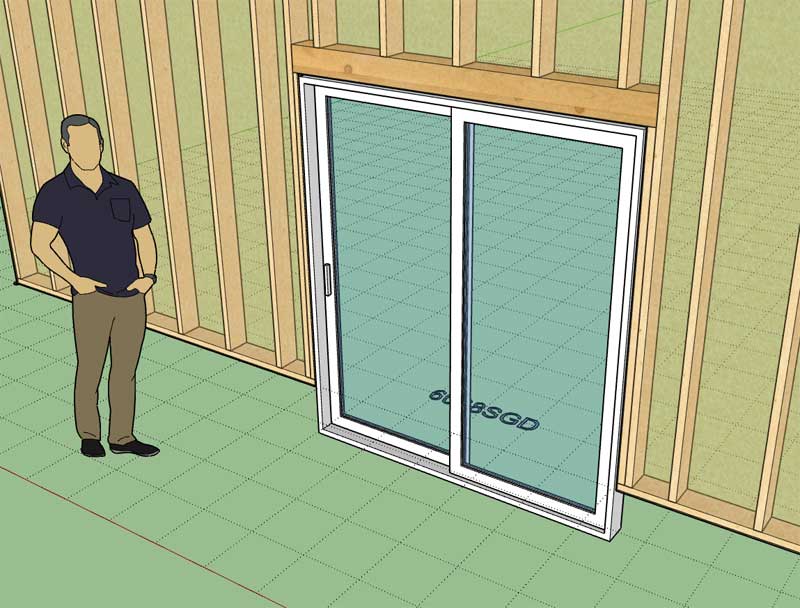
- Fixed a minor bug with sliding glass doors when the door vertical offset is a non-zero value.
1 Like
Thank you! I appreciate very much your responsiveness and getting to fixing the minor bugs that pop up.
1 Like
These type of bugs are very easy fixes. Usually I somehow missed including the offset variable in the calculation when I added the new door type and then I didn’t fully test enough permutations to realize that I missed that possible case.
Thank-you for pointing it out and allowing me to correct it.
Version 2.3.4 - 08.18.2021
- Added logic into the add and edit menus to prevent users from using single and double quotes in beam and header names.
- Added logic into all HTML menus to prevent users from using vertical bars in beam and header names and within preset names.
Version 2.3.5 - 08.21.2021
- Fixed a bug with Simpson Strong Walls when “Terminal” wall end conditions are used in a wall assembly.
- Modified the “Edit Wall Assembly” context menu tool so that it behaves similar to the “Edit Wall” tool.
- Fixed a bug with the wall stretch tool so it now allows for wall stretch or shrinks that are less than 3".
- Enabled spaced headers (2 ply or 3 ply) for windows, doors and garages by using the key word “FILL” in the header description.


*Note, that the header must by a 2 ply or 3 ply header to use a spacer as shown. Also the header description must include a string in this format “FILL_OSB_0.375” or “FILL_PLY_0.4375”. The second term is either OSB or PLY which will determine the material to use as the spacer. The third term is the thickness of the spacer (ie. 0.25, 0.375, 0.4375, 0.5 etc…). In a metric template you can specify the spacer thickness in millimeters instead of inches.
P.S.
Note that this space if often called a “flitch” plate in construction terminology.
2 Likes
Awesome! Thanks for making these tweaks! You’re fast to implement improvements ![]()
1 Like
Version 2.3.6 - 08.23.2021
- Enabled a trim option for wrapped free standing columns.

The trim combined with the cap or astragal can give even more variations.
1 Like
@medeek I’m trying to export lumber data from the model using Generate Report in order to quantify lumber in Excel differently than how your native estimating module works. The problem I’m facing is the axes are not oriented consistently for each piece of lumber so it’s hard for me to know which type of lumber it is.
I was expecting something like a 2x4 would always be X=3 1/2", Y=1 1/2", and Z=length. That way it is predictable and I can easily identify what type of lumber it is in Excel and I can tell the difference between a 2x4 and a 2x6 by testing one value. But I’m seeing stuff like this:
- Studs: Width = Y
- Center Tee Stud: Width = X
- Blocking: Width = Y
- Header Ply: Width = Z
- Bottom/Top Plate: Width = Y
Every piece of lumber has its axes oriented according to the global axis, with blue always point “up”, so it makes each piece oriented differently whether it’s lumber run vertically, horizontally, or turned 90°.
Is there a reason lumber can’t all be oriented consistently, to make it more consistent and easier to quantify?
Or do I have to create special rules in Excel for each use case so it knows which cell is the length and which is the width?
1 Like
This is an excellent point.
When I originally began the plugins (Truss and Wall) I debated how to handle this. Obviously always drawing standard lumber with the width, thickness and height along the same axis makes excellent sense and also makes applying a texture to it easier (less logic required).
The problem I saw with this course of action was that with certain members (ie. blocking, plates, headers, tee studs etc…) it would require extra steps to rotate the members once they were created. The added steps required to rotate the member into place added to the execution time while creating or editing a wall. My thinking at the time was that anything to minimize additional steps or execution time was the correct path to take.
If we are talking only a few members (ie. top and bottom wall plates) then the penalty the extra rotations incur is minimal however with something like blocking each block would be required to rotate into place, for a wall with multiple rows of blocking this becomes a significant amount of extra operations in my opinion.
However I can see the obvious advantages of having the framing oriented in a more predictable and measurable manner. I will need to give this some more thought and additional testing. I am wondering if there is a way to simply reorient the axis for the group (ie. block) and this might be less computationally expensive than a rotational transformation?
For the people who understand this API stuff better than me, feel free to weigh in here.
Thanks for the feedback.
I understand what you’re saying. You were trying to make it draw as quickly as possible. Rotating adds another step to every object. I also see what you’re saying about just changing the axes instead of rotating the object. Might be easier to implement too since you wouldn’t have to change the drawing logic you’ve already created.
I also noticed that even lumber drawn at an angle, (like top plates for a gable wall) have their axes oriented to the global axis, instead of along the lumber. That makes it really tricky to calculate.
I was going to ask how you are calculating it using the built-in estimating module, but it doesn’t seem to work on walls with sloped top plates.
1 Like
The estimating module has not been enabled yet for hip, gable and shed walls, only for rectangular walls.
Interesting that you ask because that is exactly what I am working on this morning. I will be adding in Gable walls first and then the Shed and Hip next.
The length of the sloping plates can actually be calculated by at least two ways.
1.) Bounding box calculation (front top points, then a distance calc using the API).
2.) Just a simple math calc. using the angle of incline, the horizontal projection and some trigonometry.
The wall plugin and all of the other plugins are really works in progress.
1 Like
#FeatureRequest
When inserting a door/window, allow the user to hold SHIFT while hovering on a wall, in order to lock the placement of the door/window along the current wall. This will allow the user to inference other parts of the model, without the plugin thinking I want to place the opening on a different wall.
Related idea: A lot of times, the architect will provide measurements for windows from arbitrary locations, like the centerline of something, or the face of sheathing from a different wall, or the other side of a wall. It would be helpful when inserting doors/windows if I could lock the association of the door to a specific wall, then pick two unrelated points for the dimension.
Maybe a workflow could look like this for the example below, for the door above the WIC label:
- Hover over the wall with the door tool.
- Hold SHIFT to lock association to the wall.
- Click starting point somewhere else in the model (In the example below, you’d click the outer face of sheathing of the exterior wall.)
- Type in 4’ 4" ENTER to specify the measurement to the center of the door.

So basically when holding SHIFT, the door is associated with the currently highlighted wall, and a two-click input is expected. A start and end point. If the user just wants to reference a single point elsewhere in the model, they can just double-click the point. But if they want to specify an offset, they can click two different points or type in a dimension relative to their custom starting point.
This would save from having to measure out guides with the tape measure tool and going back and forth between the door tool. Big time saver.
1 Like
You overestimate my interpretation of “simple math”. I’m getting flashbacks of SOH CAH TOA from geometry class.
But seriously, for me to try and do that in Excel, I’d have to create some kind of formula that would first be able to identify a sloping framing member, and I’d have to make some assumptions about the orientation… idk, seems a lot easier (for me, lol, not you) if I could just refer to Z length is always the length of the lumber.
They are incredibly powerful just as they are. You’ve really created a great set of tools.
2 Likes