Labelling slopes: Architects’ and Civil Engineers’ help requested!

Getting on for two years ago (June 2017), there was a thread about developing a tool following the lines of Angular Dimension 2 by me and Steve Baumgartner (@slbaumgartner), but for labelling slopes.

https://forums.sketchup.com/t/slope-pitch-dimensions

It had spun off from the Sketchup 2018 Wish List thread, (link in the first post of the above thread).

Well, after a long delay, Steve and I have started to work on an implementation of a Slope Dimension plugin.

Most uses of slope dimensions by Architects seem to be in construction documentation elevation drawings, whereas we are developing it for SketchUp in 3D.

So our first implementation will be for edges, with the slope dimension in the vertical plane including the selected edge.

But part of the earlier discussion was about putting a slope dimension on a face, not just an edge.

We have several questions about whether, and if so how, to do that.

First, DO Architects typically show slope dimensions on (for example) roof faces in SU models at all, or do Civil Engineers on sloped terrain for roads or railways, which could then be shown in plan view in construction documents, as well as in the 3D model?

Second, IF they do, how is it shown in a plan view?

I’ve only managed to find one example of a plan with pitch marked on the roof face. Arrow pointing down the slope (which I think is more common than up, unless annotated ‘up’?). And the triangle (without hypotenuse) symbol showing 6:12 pitch, with run direction horizontal. Still not obvious from that symbol which is the high end. Maybe it doesn’t matter, and you infer it from the context?

We’d be very grateful for some other ‘worked examples’ of how it’s done in a plan view (if it is commonly done at all), and suggestions for how to draw that in a 3D model in addition to the above example.

Thanks if you can help us.

In particular, to those who responded to the previous post with an example or comment about displaying a slope dimension, have you anything to add on the idea of a plan-view dimension?

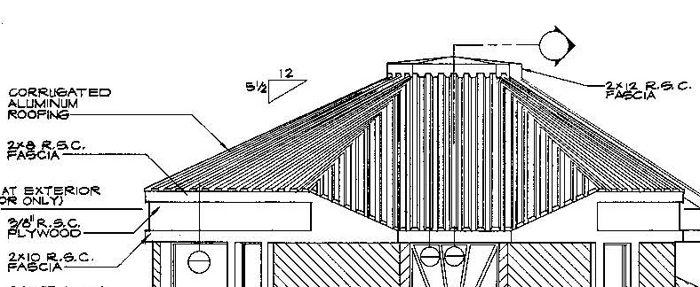
And for anyone who works in metric, even information about how you show pitch in metric in an elevation drawing would be helpful - virtually all the examples quoted, or that I can find by google search, show the US convention of rise in 12" run.

Sorry if you responded and I’ve missed adding your tag here.

@Neil_Burkholder, @Box, @Geo, @bmike, @Anssi, @JQL, @MobelDesign

This forum thread seems to indicate words (labels) should be used to indicate direction to avoid any confusion.

1 Like

Thanks, Dan.

We’ll do that, if the idea for a plan view slope dimension takes off.

That forum might be a good place to get more opinions as well.

I’ve now put up a post there. As it’s my first post on that forum, it will wait for a moderator’s approval before being displayed.

It’s now gone live - very quickly - and can be found here

1 Like

As and Architect and CAD software developer since 1977, I’ve led the development of many CAD features that address the needs of construction documents (but mostly not in SketchUp). SketchUp/Layout is still quite weak in this regard. My comments:

  • Roof slope arrows are only shown in plan view and always point down. The arrows do not extend from the ridge to the eave.

  • Ramp slope and Stair direction arrows may be up or down so require a notation (up, down) .at the base or along the line of the arrow. Usually in the center of the ramp or stair. The arrow line extends to the end edge of the ramp or last tread and start with a dot and end with an arrow. If there is a landing between segments the arrow is shown continuously along the centerline of the entire run as it turns or switches back.

The larger topic of construction documents graphic standards is vast. The bible is “Architectural Graphic Standards” by Ramsey and Sleeper.

Many CAD systems fail to make their notational elements full dynamic and/or integrated with the Physical CAD objects. Here are a few guidelines.

  1. Notational Objects should be understood by the system as inherently distinct from Physical Objects. They should automatically be viewable in separate layers from the physical objects. A given physical object may have many different notational objects pointing to it depending on the view and the drawing/discipline type. Database integrity should be maintained so that if a physical object is deleted then so should it’s notational objects.
  2. Notational Objects Usually have both text and graphic content: for example a dimension has leader lines while a room label may have several text fields displayed in a graphic input box format.
    3 Notational Objects can be of 4 general types Physical object Labels, Relationship labels, Deduced Object labels, and Schematic Objects. Here are examples of each:

Physical Object Label: for a chair this might be a single text with a leader line or a mini input box with name, manufacturer, fabric color.etc. NONE of the text content should be stored in the notational object: each text element should be retrieved for display from either the physical object component definition or its instance as defined by the setup the user performs when he designs each label type. There needs to be a label design module that allows a project manager to establish the list of allowable manufacturers, finishes, colors etc that are available for use on the project. This requires a relational database functionality absent from SketchUp

Object relationships labels: this includes standard linear, survey and arc dimensions of many types.

Deduced Object Labels: These are for labeling such things as the rooms or departments implied by walls of different types. These need to automatically updated as walls are moved, deleted etc. Since SketchUp has no “wall” element this would be quite difficult to do.

Schematic Objects: It is both unnecessary and impractical to physically model many kinds of objects. Examples; electrical wiring is displayed as a schematic with arcs linking switches, outlets and fixtures; repetitive structural members (even if individually modeled for 3D views) are better displayed on plans as a double ended span arrow with a notation like “2x16 Joists @ 16” o.c."

That’s a start.

5 Likes

Thank you, Barry. That’s very helpful about the roof plan and stair arrows.

Unfortunately, it seems somewhere between incredibly difficult and impossible, Steve tells me, to make either the Angular Dimension or Slope Dimension group associate with the objects they dimension, as recommended in the quotes you include suggest should be done.

So you have to manually delete and redraw the dimension group if the geometry changes, or delete it if the object is deleted.

I was able to develop a very useful Survey dimensioning extension (see 2DXY SiteSurvey) but I’ve stopped developing SketchUp extensions for notational purposes until SketchUp adds considerable basic functionality.

1 Like

I can only tell you what I do here in the UK as I am not aware of any accepted conventions.

I have never put a slope reference on a plan as it always seems to make more sense to me to put it where it actually appears, ie. on elevations. I have often expressed it in degrees and I have never had a builder tell me he doesn’t understand that. That may be because roofers squares do tend to have degrees marked on them. But I have also expressed slopes as a proportion and then include a small right angled triangle above the actual roof with the lengths of “opposite” and “adjacent” marked to the nearest whole number.

Here is my 2 cents.

In our parts roof slopes are indicated mainly in elevations and sections with spot elevations. Slope arrows are usually used in ramps.

Hi @john_mcclenahan and @slbaumgartner

I am pleased to share my American Architectural experiences and thoughts with you:

I think it is important to first recognize that there are “industry conventions” which become interpreted and revised as “office standards” that are then incorporated into communicating roof pitches, wall rakes, stairs, ramps, and site slope conditions by individuals. Complicating your endeavor, is that Architects, Structural Engineers, Landscape Architects and Civil Engineers all start out with different education tracks, internships and industry conventions.

Now to specifics: I think showing roof pitches in models is a new phenomenon, which I support as we move to more and more 3D models in the construction arts. For roofs in plan, best practice is to indicate water flow lines, many of us including myself (brown metal roof) and my go to resource on this topic, “The Professional Handbook of Architectural Working Drawings” by Wakita and Linde, 1984 (pencil drawing), include Roof Pitch in, ‘N’ Rise : 12 Run with water flow direction (which will be a great addition to 3D models).
190326-suf1%20Roof%20Plan

For roofs in elevation, ‘N’ Rise : 12 Run is the standard for roofers here in the US. Here are two examples, the first a drawing of mine where we have developed a blue filled in triangle as an office standard to what I was taught, and is depicted in Wakita and Linde’s example.

190326-suf1%20Elevation

Now as you consider 3D modeling, I encourage you to develop 3D graphics that can be placed on roof planes in the model and also 2D graphics (in SU) that can be utilized in LayOut. Much like @medeek is doing with his Electrical Plug-in. I think the same would apply to Civil Engineering conditions, where water flow lines are indicated and a percentage is used (sometimes a ratio is used ie: 1:50 for 2%, but this is an office standard determination, where the IBC might indicate a ratio, but most of us use a percentage).

For stairs, my experience is the direction of travel is indicated with an arrow and the word “Up” or “Down” and is based upon the “floor” you have drawn and “are on”. As an example, if you are drawing the ground floor and there is a basement set of stairs and a second floor set of stairs, going “Down” to the basement would be the direction of travel and going “Up” to the second floor would be the direction of travel. I was taught to not only indicate “Up” or “Down” but also to indicate the number of Risers @ rise inches and Treads @ depth inches (percentages and angles are not used on stairs) along the arrow line. Here is an example from Wakita and Linde:

For ramps a similar approach is taken for determining “Up” or “Down” however instead of Rise and Run, we use a ratio (this comes from ADA standards where the maximum ramp slope is 1:12 and a length of 30 feet). Note the inclusion of spot elevations and cross slopes is a blending of Civil Engineering and Landscape Architecture/Architecture.

Noting this, there is also the application of “Art” to the drawing process. Here is a terrace element of a recent project of mine. Note the larger project is centered around the main house, and therefore, I choose to have the direction of travel start at the house (rather than the terrace).

Good luck with your efforts.

Hi @john_mcclenahan

An thanks for inviting me to the party.

I represent roof slopes only for “horizontal” roofs because they often have a slight slope of around 2%. Arrows in that case are pointing down.

This goes for all floors or surfaces that look horizontal but are actually slopped: Bathroom floors, showers, countertops, exterior pavements, etc…

Where slope arrows go up is on ramps, which I interpret as stairs and I’ve always seen stair arrows go up.

In here, slopes are measured in percentage. It think the reason is simple as it might help calculating them in construction site or in project. All regulations and product sheets assign percentage for slopes too.

For ramps those two triangle lines are often used too, but I think it interferes too much with architectural geometry representation so I prefer arrows.

There is a workflow issue for having slopes representation inside sketchup and not layout which is CAD export. Sketchup text will export as vector lines, not text, if you use Layout for DWG export.

So, I would rather have a special Layout TAG for slopes than a Sketchup plugin. The bridge between Sketchup geometric data and Layout autotext, leaders and dimensions is often not deep enough.

I could use someplugin that would automatically add an attribute to a Sketchup object like a face or a component/group with the clicked surface slope. This attribute could then be used inside Layout.

So, to solve this data transfer issue, what we need might be some sort of auto tag system that carries the needed info into Layout and would then allow us to use the auto tag system to retrieve the info.

Beyond slopes this could also be used to tag floor heights which is now impossible to retrieve as you cannot pick the height of a surface, only a vertex.

This sort of stuff is terrible missed in the Sketchup+Layout workflow and it requires a lot of manual labour and workarounds to make it work.

Thanks for taking the time to dig into this issue.

Thank, @JQL. I don’t myself know much about how Sketchup to Layout Tags work, but can research it. I know that neither I nor Steve use Layout much, but he might be able to attach a slope tag to a face that has a slope dimension.

Actually a height tag would also help in vertexes as Picking a vertex doesn’t allow for a single coordinate to be retrieved. You can only retrieve all X, Y and Z coordinates, you cannot isolate Z.

At the same time the Z coordinate of the model doesn’t necessarily represent the building height you need. You might have model Z=0 at a different level than sea level and if you need to represent actual height based on Sea level you can’t without having a datum.

The reverse is also true, you might have your model coordinates referring to sea level but want your height datum to be at the entrance door sill level or another logical place in the building (here this is often mandatory in some municipalities, for permit drawings)

TIG has a plugin Add Height from Datum on SketchUcation that does the height tagging. See

Does that seem to do what you want?

I use that plugin but it features the same issue. The height tag is going to export as vector lines into cad.

So I use it to get the coordinates but then so redo them in Layout one by one so I can export them to CAD. It’s stupid work, I know, but it’s the best I could find.

So what I’ve asked in the past was for a way to tag heights from models from within Layout. That would seem to me to be rather basic as Layout is already able to have a coordinate tag for vertexes. The issue with that is stated in the post above. It doesn’t fit the needs of architects.

Tagging face heights would, as Layout auto tag can retrieve custom attributes

I understand the issue a bit better now, but I don’t think our work is going to fix it for you. Sorry.

Sounds more like an issue for the Layout programming team, if TIG’s plugin doesn’t do it for you.

No problem. Sharing ideas is always gain enough!

Good luck with your work!

It’s less controversial than it used to be, but in general I am of the camp who believes that annotation is the job of LayOut not SketchUp. But, a) there is not yet an extension API for Layout so we can’t implement a new feature there (and so far as I can see the current Layout bits in the SketchUp Ruby API don’t offer what we need) and b) there are some situations in which a user wants to show some annotation in SketchUp - for better or worse. So for the time being we are working on an extension for SketchUp.

Thanks for your input, though! We are seeking to understand users’ needs and existing conventions so as to make something that is actually useful.