DL8 think same problems
Your lower stair steps are too big, and on the edge of too steep, for most building codes. Approx 10 1/4 going and 9 1/4 rise will be both dangerous and uncomfortable to use. The angle is just about ok, but you need to try smaller steps on the straight stretch at least.
Why are none of the dimension round numbers? The outer radius of the spiral parts looks as though you intended 3’6, but it isn’t quite that. And the two floors are quite different.
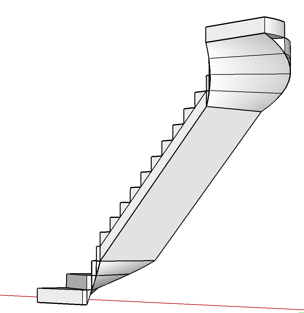
I’ve drawn most of the lower stairs using a rise of 7", four instead of three spiral steps in the 90° bends, and a going to fit the available length - 10 treads in about 74 1/2" (6’ 2 1/2"), so just under 7 1/2" going.
I used the plugin I mentioned earlier to make two different helical ramp infills, and I ‘hand stitched’ the curved triangular infills. I haven’t done the outsides. You could add that yourself - just draw a series of connected triangles on the endpoints of the curve, make into a component, repeat with a rotation for the other gaps, and smooth the surface.
It was quite fiddly to get the parameters correct for the helical ramp parts. One is 3/16 of a turn, the other a quarter turn. And if you use too few curve segments (as I did initially) the plugin rounds up the number of segments, and ended up too high as a result.
Stairs with spiral ends.skp (53.5 KB)

The stairs look covered externally, but it needs more thought about how you would make curved stringers or otherwise support the steps for the spiral parts of the curve, and actually construct the stairs.
Here is the component ‘in situ’ in your original v8 drawing:

See this related thread to which I responded earlier:
first of all: thank to all of you for your help. Even if I think I was not clear, I surely learnt things from all of your considerations.
The core of the problem is that I already have that kind of stairs, I have to keep it and I didn’ t invented anything.

I attach the a screen where I compare ‘‘my’’ stairs with the one of @john_mcclenahan to explain better: surely I am not able to make the bottom part as you did - and I hope to learn about it - but unluckily I can’ t change the shape, the number of steps and so on.
About measurements: I draw in millimeters, perhaps this is why every measure is not rounded.
But it could be also because there was an existing plan and sometimes I matched its edges.
About versions: v6 and v8 are the same files, only with another surface in the bottom part because I was working on it.
So. If you have an irregular, tremendous shape… which solution would you do to make the bottom part of stairs?
Well, although your existing stairs have steps that are too high, they would still need a helical ramp shape to cover the spiral sections. Don’t they feel very steep?
Try changing the parameters in a copy of the helical sections in my model to fit your stairs. You’ll need to install the SU draw parametric shapes plugin first.
For the bottom section you need a 60° or 0.1666667 of a revolution, a starting and ending radius to match the inside end of a spiral tread, and a width to match the width of the spiral tread, a staring height of 0, and an ending height of three treads high.
The upper one needs a quarter turn, a start height of zero and an end height of four risers, then move and rotate it into position as I did.
If you place it in a model using mm units, it should adapt to those.
I handle a number of these issues with stairmaker.

and the bottom of the stair

email me at gkernan@telus.net if you are interested in further communication
the plugin ware house
Viriga: now that I have scolded you a little hope this helps:
1 Do not fixate on the skinng of the stairs bottom now. There are a number of plugins for you to use and ther first order of business should be the stair way design:
2 )Who ever gave you the CAD drawing has given you almost all the info you need to lay out the stairs. Just make sure their scales are correct which my measurements indicated they are but , you should always check;
3Assuming the CAD drawing cannot be changed you will have to do two separate designs, Stairs have some very specific design safety requirements, if you boss has not given those to you ask. They can be different for the local codes folks in your area;
4 In you design use mostly components, that makes changes much easier. You can use much of what you already have.
In addition you can easily replace components in you drawing with those from your component browser, just select dwg ones and then in browser select option to replace selected;
5) I measured req rise for first floor case at 126.0i5" and for nominal rise ( 7") that means the number rounded to 18 but, one less is really needed so 17 required. I got 105.512" for second or 14 required
6 ) For run that can be measured from the cad image and rise + plus run = 15 is one rule of thumb is some times used. That FFWW PDF I gave you has others if also shows you the travel path allowance:grinning:
Note;many locales have a very tight tolerance of the allowable variation of the rise ( In the medieval days rise was varied on purpose to slow down invaders) The caes are separate enough think should apply separately, question for boss if you have that spec.
7) If I get bored with NFL game I may work some on the first floor case.
Post back when you get design done . I am thinking you may need knee wall to support winders or dados in stringer for support.
Good Luck
I’m still unclear if you are drawing an existing staircase, or redrawing in SU a proposed design for which you have a dwg file.
Which is it, out of curiosity? Or something else? And what do you need the drawing for?
You say you can’t change the rise and going, but the bottom stairs really seem to have dangerously high risers, and steep slope.
My assumption, the layers images have jpg of cad files that show the layouts and the OP has the task of making the stairs.
The problem he / she does not have all the design info to do properly in my MHO nor has not used info provided. The OPs profile has link to company I assume he is working for and is close to a design if he is willing to take the suggestions.
Typical issue jpg images do not allow one to make accurate model and maybe part of problem or at least I have that issue on may old machine:neutral_face:
hi you all,
I am sorry if I didn’t answer you quickly, but I had a deadline.
-
at the end curviloft was very very very helpful for me for other issues (railing…). It is very easy to use. Thank you @spawn and @TIG!
-
the stairs are existing and I need to reproduce them only for an aesthetic issue. I don’t like to leave empty a part of a building even if I don’t touch it

I can’t modify them, re-design them again, destroy them etc. etc. etc. It would be wonderful, but I can’t.
I know that the steps are irregular, high, not comfortable, but they are in this way. You should come to Sicily (Italy), there are a lot of historical palaces with this kind of construction. Most of them were built when there were no regulations about it.
Ahah I love that you focused on it but really, in this moment it is not the point for me, the real problem was to make an irregular surface having some borders already defined.
thank you to all of you ![]()