Hmm, then bad idea to use DXF Blocks … ![]()
And everything will stay totally flat.
Hmm, then bad idea to use DXF Blocks … ![]()
And everything will stay totally flat.
Blocks in Autocad were for 2 purposes. Group things together and to save resources so you could have one set of data for a group of cad entities used multiple times in a single drawing.
Xrefs were another Autocad thing to store groups of items in a file for reference in other drawings. Xrefs and Blocks were from the early days of computing when memory and resources were scarce.
You could think of Xrefs as a dumb version of Components in SketchUp.
For woodworking and for me cabinetmaking specifically, memory is no longer scare so groups is all we need. You can group 3d items that will have z values just as easy as you can group 2d items.
Early in those CNC software days Autocad was one of the few cad tools being used so software companies wrote their programs specifically for using Autocad DXFs with Blocks. At some point at least a couple of the machinery makers thought they would try their hand at software and they copied software developers that were using DXFs with blocks.
As more cad programs and specialized cabinet design programs became available the use of block went away.
Make your DXF from the topmost face of the item.
Go through the item’s geometry and divide the edges by layer [tag] into outer loops, inner loops, holes below a chosen radius, ‘pockets’ which are recesses from the topmost face that do not fully penetrate the item.
These’ ‘pockets’ need their own layers - each have the cut depth in the name.
So…
The outer-loop sets the tool path to cut out the item.
The inner-loop[s] set any through holes to be cut within the item.
Any smaller holes might be used to define preformed drill-holes in the item.
The pockets will define where the item has recesses which have a given depth - discoverable from the layer’s name-suffix - e.g ‘pocket-5mm’. These pockets might be on an outer- or inner-loop and so will need ‘trapping’ to form the whole ‘pocket’ recess…
Hope this helps…
Blocks work very well in AutoCAD or other Editors to recreate SketchUp’s components behavior.
Even if a part is present X times in the final drawing, you just have to declare it one time an insert it anywhere you want.
And if you mix it with layer you can embed useful structure (of a cutting diagram for example).
This is what my previous example did … Unfortunately it seems that major CAM softwares ignore DXF blocks … ![]()
sheet_002.dxf (12,2 Ko)
Xrefs is for mapping external file. I 'm not sure it will be more compatible to create several files.
Hi @TIG, thank you for your feedbacks.
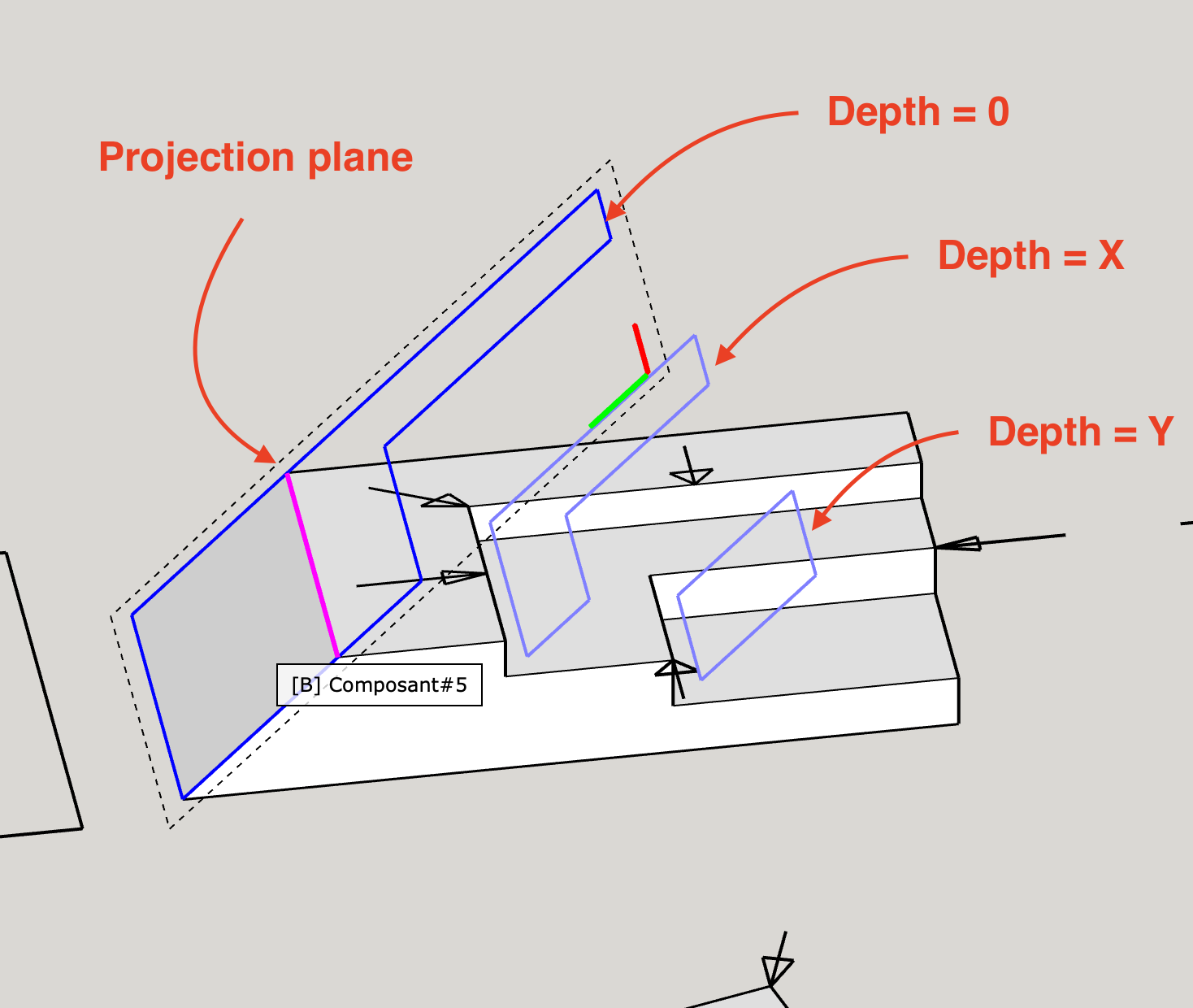
You suggestion is near what I do. I just do not directly use faces and edges data, but a projection of the whole part geometry on the desired plane.
This is a quite useless case, but this show how the part is “viewed”.
My code check if loops are CCW or CW to define if path is inner or outer.
Dashed stroke represents holes.
This permit to create a true “view” of a part by excluding what is hidden.
All faces that are not coplanar to the projection plane are considered at depth of their nearest point by their parallel projection.
And curved surfaces are merged in one unique face.

Hi,
To continue thinking about what OpenCutList can export, I would like to present 2 solutions for an example situation.
Currently the main objective of the export feature of OpenCutList is to export useful informations that can be used in multiple situations. Not just to send to a CNC.
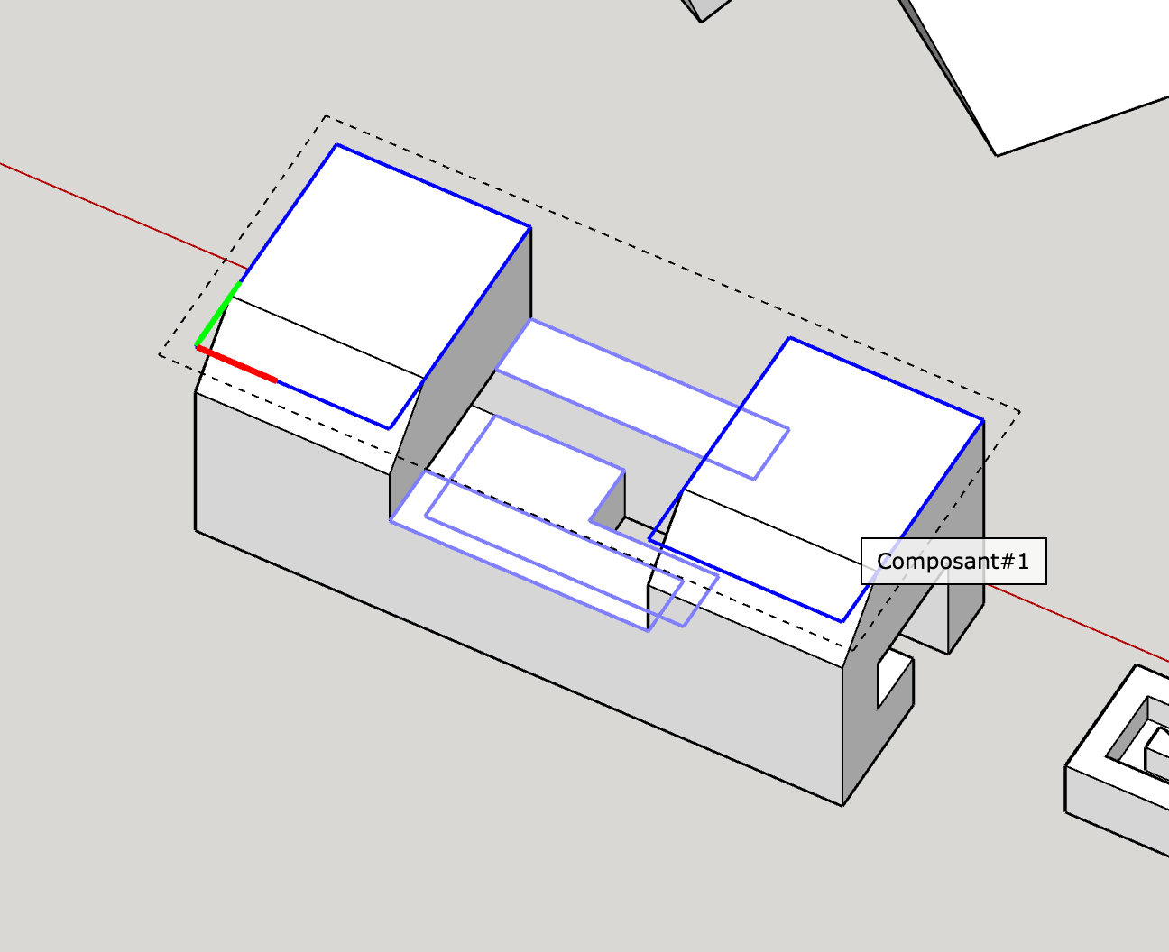
Imagine this base part :
First we can export each portion of visible faces on separated “virtual” layers. Each layer correspond to a specific depth.
In this case, layers can contains holes. It exports the strict geometry in 2D without thinking on how machining could be done.
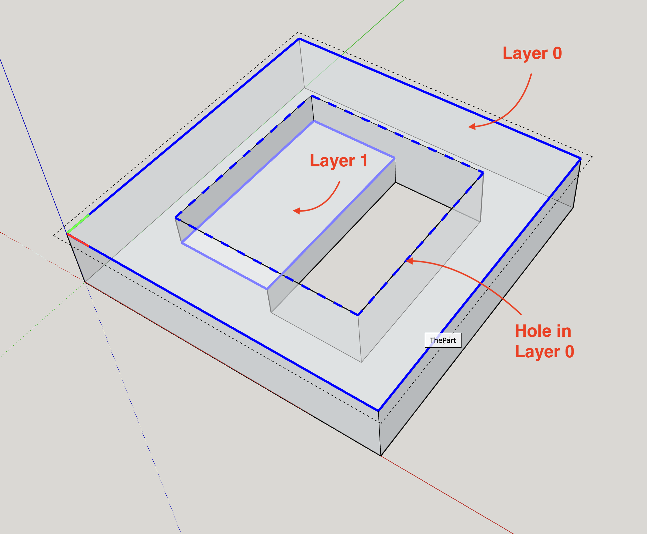
A more advance approach could be to move down all passthrough holes to a “bottom” layer (layer 2 in the image below) and merge from lower to upper layers.
What could be your opinion on these two solutions?
Should it remain a user-configurable choice?
Have a nice day ![]()
Your considerations show how tricky this actually is. I am actually torn between the different approaches and I am not super happy about it creating multiple lines on top of each other. The “classic” way of drawing this geometry (if you would draw it in AutoCad 2D from scratch) would be two rectangles (the outline and the cutout) and one line in the middle of the cutout. But as said - absolutely not sure what the best version is.
I see that you also have an option “export 3D Part” in your Beta version. What is your plan with this? At the moment it does basically the same thing that the regular export option does, correct?
Hi @napperkt, thank you for your feedback !
Yes, but by removing all “double” lines, we loose a lot of data.
Currently my approach is to keep each geometry by creating a layer for each depth.
Then this 3D part :
Strategy 1
Exported to 2 different layers in final DXF
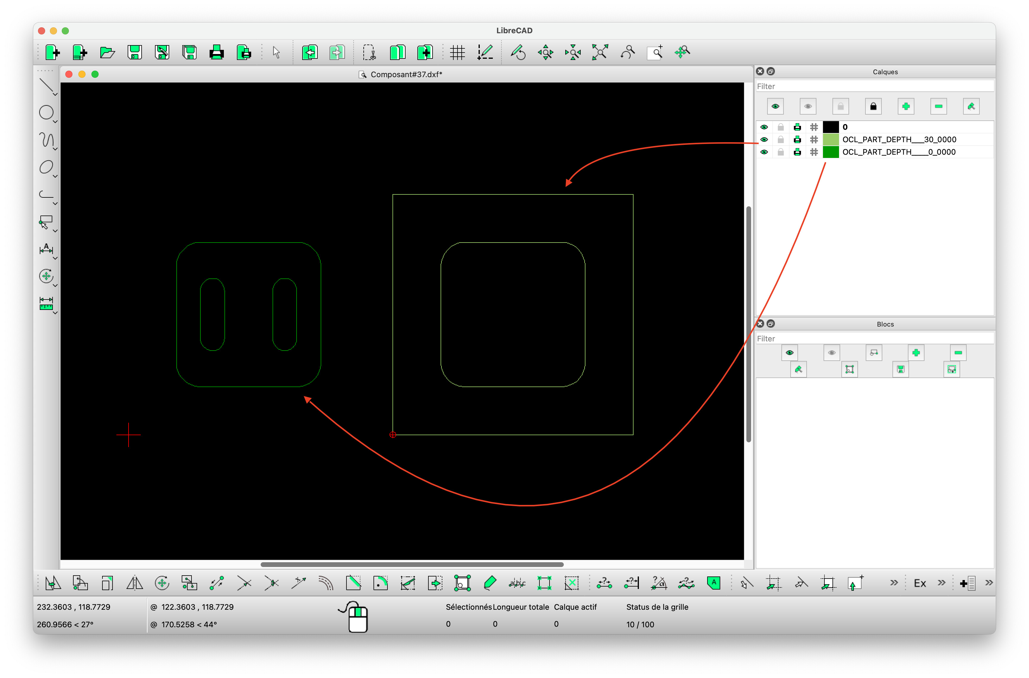
Strategy 2
Exported to 3 different layers in final DXF
(In this screenshot I move each layer lines along X axis)
Layers permit to keep exact shapes of each depth.
Isn’t it a useful solution in your process ?
This feature is designed to export mesh geometry to a 3D format like STL and OBJ. (I will abandon DXF 3D, complex and not better than STL to represent a mesh)
This feature mainly target 3D Printers.
I can definitely live with the double-lines - it’s still so much better than anything we have at the moment! ![]()
Regarding the 3D parts - as a mesh I dig it. I thought for a moment you are going for a “proper” 3D dwg file without the meshes - but that is a bit of a holy grail as it would mean redrawing the entire part in a “non-sketchup” like fashion.
What would be awesome in the end would be a multiple part exporter - strategy could be foreach part selected use largest side face (to determine from what direction you want to look at the part) → run export routine… Export could be a ZIP so you’d only have one “click to save” userinteaction.
Already finding circles in 2D is complicated so, pushing that to 3D surfaces… ![]()
Yes, I have this in mind. This in on the todo list.
Maybe not in a zip file, but on a folder. Like exporting cutting diagrams works.
Currently you already can to it through a cutting diagram. But yes part should share the same thickness and are exported in the same DXF file.
Gostaria se pudesse compartilhar sobre essa arquitetura, preciso gerar dxf para cortar minhas peças na router, se pudesse compartilhar. as peças são de cortes unicos.
Thanks to the support of many OpenCutList users, we have reached the target of US $ 8000.
We especially thank Jörg, who reached the finish line with all of us thanks to a double donation.
Before we can publish this version 6.0, we still have a lot of work to do. We have to thoroughly test all the new features, translate the texts into all languages and complete the documentation.
So please be patient, but we are on the right track.
We send you our best wishes for the last weeks of 2023.
I read this whole tread with great interest. Sometimes, events just converge in time, such that it seems right to engage. Just a couple of days ago, the originators of the WikiHouse concept (they now go under the company name Open Systems Lab) I saw news about their new design-kit “Skylark”. It can be downloaded as a Sketchup file (https://github.wikihouse.cc/Skylark/raw/main/SKYLARK250/Design%20kit/SKYLARK250_design-kit_detailed/SKYLARK250_design-kit_sketchup/SKYLARK250_design-kit_blocks_detailed.skp).
As I look through their building elements, I am reminded of how much work can go into turning 3D models into DXF files for import in milling software. Fair enough, they have prepared DXF that can be downloaded from their GitHub page. But I wanted to see if I could find an extension for Sketchup that could be helpful for this. As a side note, I learned from one of their developers that they’ve laid out the DXF files by hand. I searched the Extension Warehouse and Sketchucation with the keywords “WikiHouse” and “CNC”, but I didn’t find your extension initially - just by accident did I see this tread a digest newsletter from this forum.
There was a Wikihouse-plugin, but it hasn’t been updated for 10 years. From the renowned @thomthom 's GitHub page, I could see that he made a fork of this as well. He has also made an extension called Milling Tools. These extensions has only dealt with flattening of assemblies and their layout on sheets, and has not dealt with DXF export (to my knowledge).
Also accidentally, on a FreeCAD forum, I just saw someone referring to your extension (with a link to it featured on the MasterSketchUp channel on Youtube) with a wish that something like this existed for FreeCAD too.
I think your extension and its further development is a valuable asset for makers and workshops in general. I think it can be particularly useful for those who want to participate in WikiHouse projects, using Sketchup.
Hi @torbjo1405,
First, I pleased to see that OpenCutList can explore new horizons with those news features.
But searching the full automated process will be quite hard.
Here is what I can try to export from WikiHouse SKP model with our current DEV code.
The first nice thing is that most parts are correctly exported in few clicks.
But some adjustments need to be done in the model and in the code go further.
Component Axes
As you can see component axes are not always aligned along stair stringer, and OCL pack all parts as boxes.
And here the generated DXF : sheet_001.dxf (61,1 Ko)
Milling shapes
Currently I do not find a general way to correctly offset milling shapes.
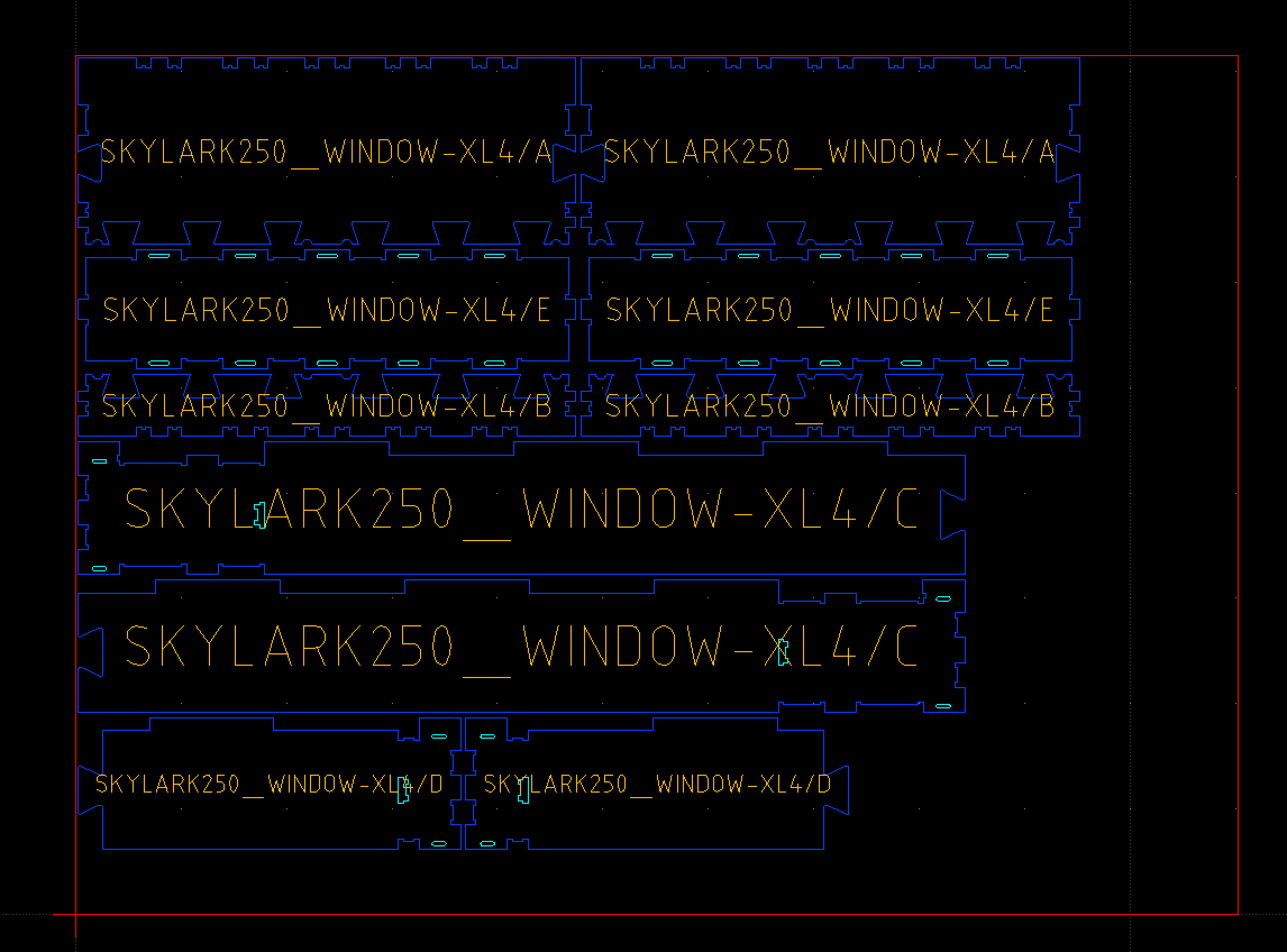
Part identification
Currently part identification are not designed to be used for milling. Just to help the operator. Then text can overlap cuts.
Exciting that you looked into your extension’s use on Wikihouse assemblies already! I think your pictures are at least a proof of concept.
Disclaimer, I am not closely engaged with the current (if ever) nitty-gritty details of Wikihouse design and manufacturing. I only offer my impressions from the sideline.
The DXF files they have, has been laid out by hand, per assembled component - that must be a tedious undertaking and not optimal for material use and time in manufacturing. An automatic layout (and DXF generation) of any assembly would be a huge win in itself. There can be a division of labour between design and manufacture, and toolpaths and offsets can be handled by the CNC operator (I believe they have a separate manufacturing guide). Other times you might want to laser-cut a downscaled set, for testing. The part naming on the shapes is ideal for keeping them apart, and a time-saver too. I don’t think it’s a practical necessity to carve the names.
I think the diagonal layout of parts that are off axis is unfortunate. Could you maybe rotate the parts until its longest edge aligns with its bounding box? There used to be big L-shaped parts too, but I am not sure if they’re still in the current design-kits.
OpenCutList embed a tool to change component axes along longest edge with the Adapt Axes.
More generally the WikiHouse Sketchup Model is not always accurate. Some arcs are converted to 5 points. It’s not enough for OCL algorithm to convert it to a true DXF arc. And part are generated with too complex geometry that slowdown all treatments and distord results.
I have looked closer at the Wikihouse Sketchup model myself, and I am astonished! It consists of remarkable bad geometry, at least it is way to much of it, that’s why it’s 69MB. The blender file is even worse (240MB+), and the IFC file is utterly rubbish.
The Sketchup model could need some love. It would be best to remake the components from the DXF files, those are clean. (image attached)
I am not sure if it’s really neccessary to model a WikiHouse in detail. It would be way simpler to model with representative blocks/modules, export a list of block/modules, and then a spreadsheet to count the number of different parts. Then it wouldn’t make sense to layout the model directly to DXF either, but rather use a scripting environment (maybe Python or OpensSCAD) together with a library of existing DXF files.
An idea for some future minor update. AFAIU due to Sketchup limitations you won’t be able to automatically align efficiently non-rectangular details for cutting. So maybe it is worth to add an option to place those (non rectangular) details separately? Then we could get automatic cutting diagram for rectangular details and align non-rectangular details manually, currently all details will be mixed making auto alignment useless or at least not efficient. In case there are both types of details in project this option would save us some time.
Also I have a feature idea related to the main topic of 6.0 update - DXF export.
The concept is to add an option for grain direction reflection in resulted DXF. Often the resulted DXF will be further edited using special software or manually to achieve proper details layout. If edited manually some sort of grain direction mark (e.g. arrow) would be beneficial, for automatic alignment splitting details with different types of grain direction into two separate files would be beneficial. Without any marking it’s rather difficult to understand in DXF what particular details you’re dealing with and how it should be oriented. Thank you for all your efforts, the plugin is wonderful!
This will be possible because you can easily select only a set of “rectangular” part to compute cutting diagram. And export the rest to separated files that you can “arrange” with your favorite external tool.
If grain direction exists on a material defined with OpenCutList, it is always aligned along X axis (length) of the resulting DXF when exporting part .