Thank you. The “find center” option in the context menu is just the thing, but I’m not sure why it is hidden there rather than functioning with the other snap tools.
I’d made mention of drawing the lines from the center point but was still interested to know if there was a control key to use in conjunction with the tape measure tool to be able to draw a line out from the center of a segment; as when using it on a center point produces a parallel line and not a perpendicular one. Would be nice if a ctrl/shift combo forced it to behave differently. Tom’s suggestion of the protractor works great but I guess that’s not my “go to” tool, but now it will be.
A very, very old post but just coming into it now…
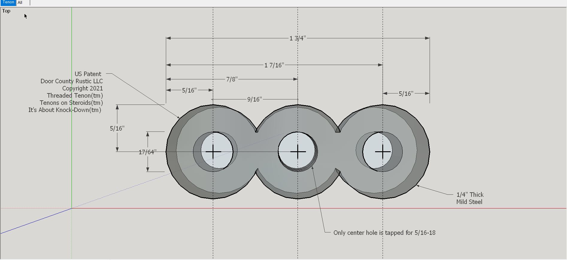
For what it is worth… I was forced into figuring out how to deal with circles, arcs, slots and cylinders when applying for a patent. It was have the attorney outsource my invention to a third party for the patent application drawings to the tune of $10,000 or do my own. Since this was a “bucket list hobby thing” I chose the latter. All of These drawings filed with the USPTO were done in SketchUp.
The “hack” I used and have never looked back on is to create “crosshairs” at the center of every circle. My typical steps would be as follows:
1 - Using two Guidelines draw a circle (for a 5/16" bolt I would draw a 5/32(r) circle making sure I drag the radius along one of the guidelines (up/down or left/right) which helps later with dimensioning.
2 - Immediately make that circle a Component
3 - With Guidelines still in place use short Lines to create 4 intersecting lines aka “Crosshairs”. Those crosshairs must ALWAYS be shorter than the diameter of the circle otherwise they break the circle.
4 - From there I Push/Pull in one or both directions.
- For a hex bolt I would Push say 2" for a 2" bolt
- Next I would use Polygon from that same crosshairs to form the hex and then Pull that say 3/16
From there it gets even more complicated when getting into different kinds of bolts or my favorite GRK RSS screws…
That bolt is normally intended to go into a board or threaded metal so I go into edit mode of the board/threaded metal (already its own Component) and create a circle on the surface then create crosshairs in that circle as well usually with the crosshairs turned 45 degrees so easier to distinguish between the bolt/screw vs the board.
After that I can place any bolt/screw on the appropriate board/threaded metal piece at precisely the point where the two will meet in real life. This is made really simple by go into X-Ray mode which allows me to “Move” (M) or Copy/Move (Ctrl M) by grabbing the cross hairs on the bolt and dragging it to the crosshairs on the board. Still amazes me how SketchUp anticipates where I am trying to go and focuses the two crosshairs! (See short video attached - Guideline to a crosshairs, then grabbing crosshairs on bolt and dragging to crosshairs on board).
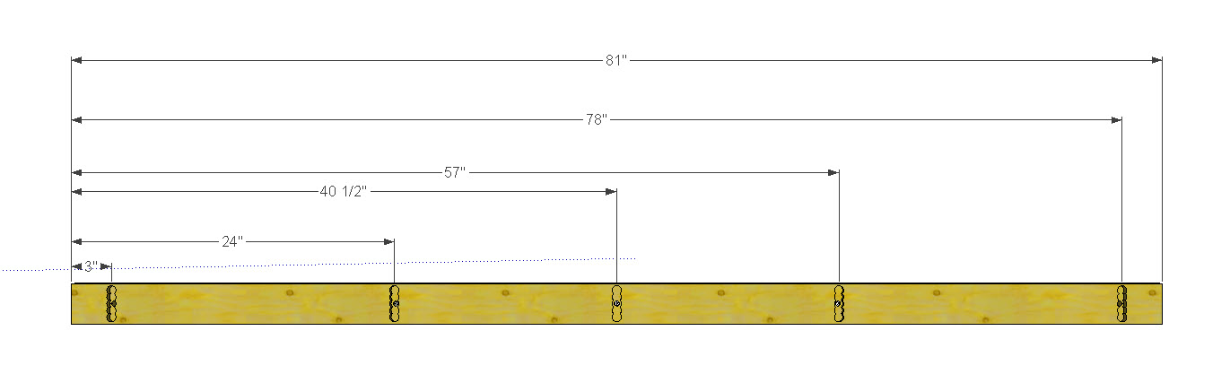
Really glad I bit the bullet to apply this method as it comes in really handy when creating CutLists for some pretty complicated woodworking projects. In those CutList I dimension all holes, bolts, screws and even arches based on the “crosshairs” C/L of that item. (See image attached of long board dimensioned to the C/L of each circle where it will get drilled on drillpress).
If I need to relocate a hole in the board I start by placing two Guideline at 90 degrees where I want the hole to be relocated, go over to the crosshairs of the hole, M that to the new location by placing the crosshairs over the intersecting guidelines. Another benefit of working from the C/L of each hole is that is drill bits, at least in Wisconsin, are also round and so when laying out a board to be drilled on a drill press I can set the tape on one end, mark each C/L location and then have at it on the drill press.
One last note: Although the crosshairs work great everywhere else they became a minor irritation when creating drawings in SketchUp to convert to Vcarve for CNC. When importing the 2D SketchUp file into Vcarve the crosshairs come with. When selecting multiple circles/arches by dragging the cursor it also selects the crosshairs. No big deal since, at least in Wisconsin, our 1/4" upspiral router bits can not make a crosshairs consisting of lines only 1/1000" wide. When clicking on “Calculate” in Vcarve it pops up a warning that certain items were disregarded, those being the crosshairs, but it still selects the actual circles (as long as those are equal to or greater in size than the bit).
Mike
Reading through this it sounds like in some cases you are making more work for yourself than is needed. As long as it works for you that’s cool, though.
And this is in SketchUp Make? I had a look at your business site. Interesting.
Totally open for a simpler way to deal with circles and cylinders especially relative to bolts, screws, woodworking and creating cutlists. If you know of any posts providing a simpler method please post a link. Where I find doing the crosshairs comes in really handy is for dimensioning of my woodworking projects. The crosshairs makes running Guidelines to each C/L, especially the small holes on a long board, where then the dimensioning tool can find each. Again, totally open to an easier way but have not run across any yet for my applications.
Regarding using “Make”… Up until now this was actually a “hobby”, a “bucket list” thing, that is, applying for a patent. Actually budgeted part of my social security checks to pay the attorney so I think it doesn’t get any more “hobbyish” than that. I am otherwise retired and so had been using Make to do my own woodworking and testing for possible business applications. Don’t know that this will ever go into an actual business or commercial as I understood Make Vs Pro but, based on your comment, have downloaded Pro and will transition to that.
Mike