Oh! Rockin’! I’ll try that next time.
Thanks!
Jay
Oh! Rockin’! I’ll try that next time.
Thanks!
Jay
You miss my point. You are making your dimensions unnecessarily difficult to work with (according to you) because you have chosen to retain the value of a common fraction even though you’re working with decimals.
Indeed, what is equally common is for a tolerance to be associated with a dimension based on the number of decimal places to which it is stated. Commonly, two places gets a loose tolerance, such as ±.03 and three places gets a tighter tolerance, such as ±.010. Your three-place dimension denotes a certain need for precision but seems to be merely an artifact of a system (fractional inches) you’re not using.
-Gully
I don’t understand the distinction. If a diameter is called out on a blueprint as 8.79 millimeters, the radius isn’t any more easy to calculate than if it was 0.625 inches. If you’re designing something that doesn’t have to fit something that’s already made, you can pick whatever round numbers that make you happy. However, many times you don’t have any control over the dimensions required for a part. I spent more than twenty years making molds that had to be accurate to +/- 0.0005". Between the part design and the shrink factor and electrode overburn, none of the numbers ever came out simple … something like 1.3875463" was the norm. If you needed half of that, you used a calculator.
Quite right. I was questioning whether the trailing .005 was really needed or was merely a reflex. If it is essential to the design, that’s another matter.
Really, there are two questions: 1) what is the basic dimensional requirement? 2) How much precision is needed in its manufacture?
-Gully
For some of the dimensions, it will be important to get it to the thousandth when I do the machine work. For other dimensions, winging it will work. For the .625" I mentioned, it’s important.
Sure, okay, but when you say “to the thousandth,” that includes .620 (just as one of your examples is .550).
I’m not suggesting you exclude all (or any) three-place dimensions. Actually, of the three-place dimensions you listed as examples, .625", .550", .605", and .806", the only one that is remarkable is the first, not because it’s in thousandths but because it is the exact equivalent value to a common fraction, a coincidence?
-Gully
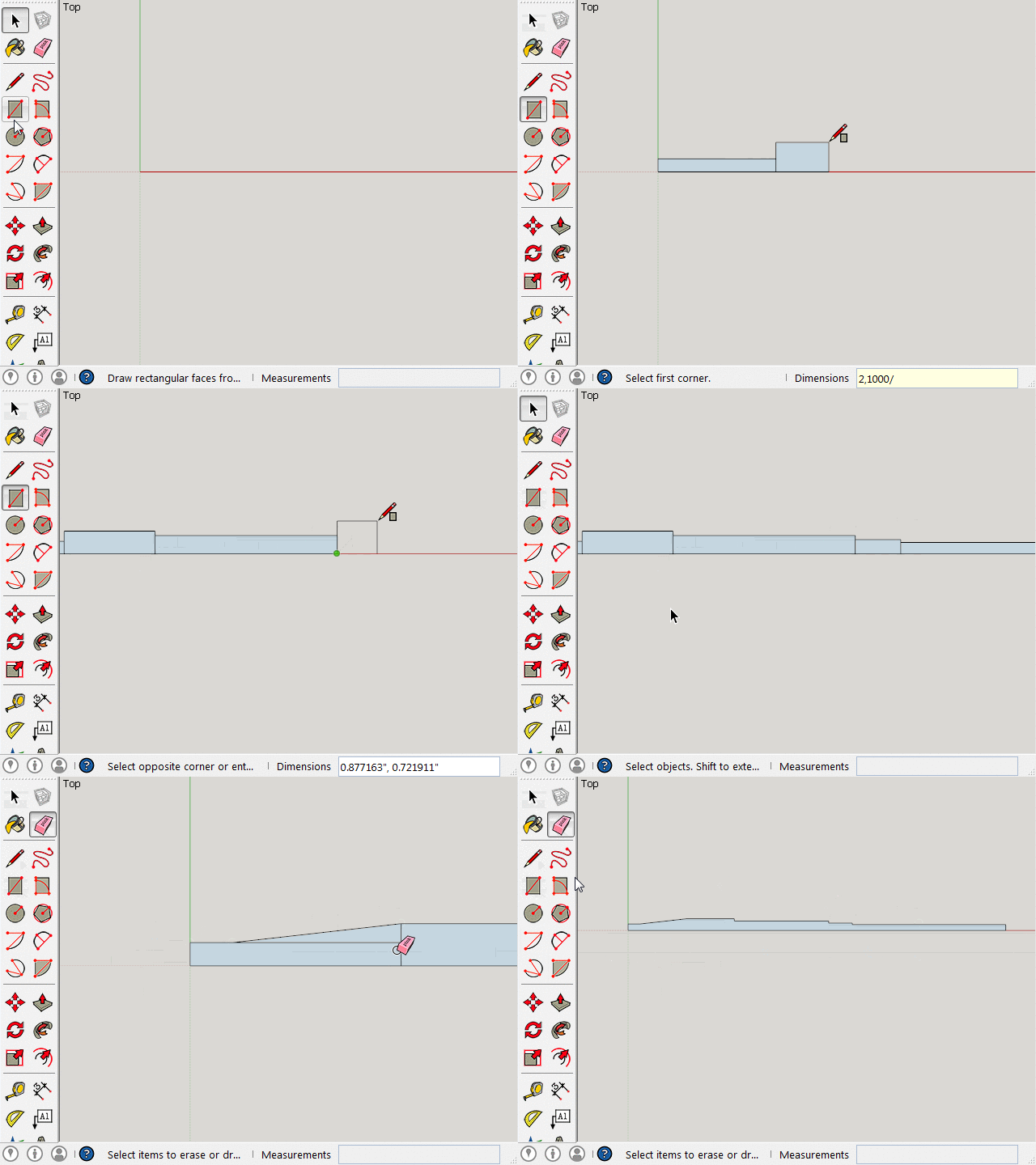
I don’t generally use fractions if I can avoid it, but “to the thousandth” (in the Imperial world) means something like 625/1000 … not 620/1000 or 630/1000. Otherwise it would be in “hundredths” as 62/100 or 63/100. As it applies to @birdus’s project, a 0.625" (or 5/8") diameter can be expressed as 625/1000 and the radius as 625/2000. Since SketchUp accepts inches in fractional format, this allows for something like:

Hi folks.
Let SketchUp do the math.
Enter the diameter value as the radius that you require when drawing the profile. However, use the correct length.
Of course the part will be to thick.
Then, when done drawing the profile, scale it by 0.5 in the direction corresponding to the width of the profile to bring it back to correct dimensions. Then do the lathing operation.
This is if you draw a half profile.
If you draw a full profile, use the diameter values. IMHO this is the method I would use.
Just ideas.
Jean
At the real risk of this topic becoming tedious, in the world of American aerospace engineering drawing practices, precision, or number of decimal places, is associated with a certain tolerance range: a value stated to three places gets a tighter manufacturing tolerance than one stated to two places, so .620 is a different dimension than .62, calling for a different inspection regimen and possibly a different manufacturing process.
Although it is not the practice on metric drawings, on US inch drawings, a tolerance is required to be stated to the same number of decimal places as the basic dimension it modifies, so if I needed a ±.0005 tolerance for a particular dimension, I’d be required to state the nominal dimension to four places, even if that were .6200, thus .6200±.0005, not .62±.0005.
-Gully
At the risk…that train left some time ago.
Lucky you’re here to keep things interesting.
-G
Good idea, Jean. That definitely helps to streamline the process.
Thanks,
Jay
One more question on topic. After my drawing is done, is there any way to change the diameter of a section (easily)? I fear not, but thought I’d ask since I’m clearly a neophyte.
Thanks,
Jay
You can change the size of individual features with judicious use of the Scale tool. It probably won’t be easy the first few times you try it. There are some subtle aspects to the procedure that may not be obvious the first few times. However, attempts 10 through n should be pretty easy.
-Gully
Edit: Depending on the circumstances, the Move tool can also be used to resize and relocate features.
birdus:
Su usually can model items several different ways. The Follow me and the push / pull tool approaches looks the same on the outside but, detailed look will show some major differences for the internal details. The PP toll should give you a cleaner model. Travelling 24 early AM so time limited for check now. If you make the individual sections of Jims approach components you can probably scale easier vs.follow tool approach.
BTW we use to be able to do simple math in the VCB, if not removed you may still be able to input dia/2. Lots of discussion about tol but done about chamfer which you will get with real tool. Depending what your plans you may have to worry?