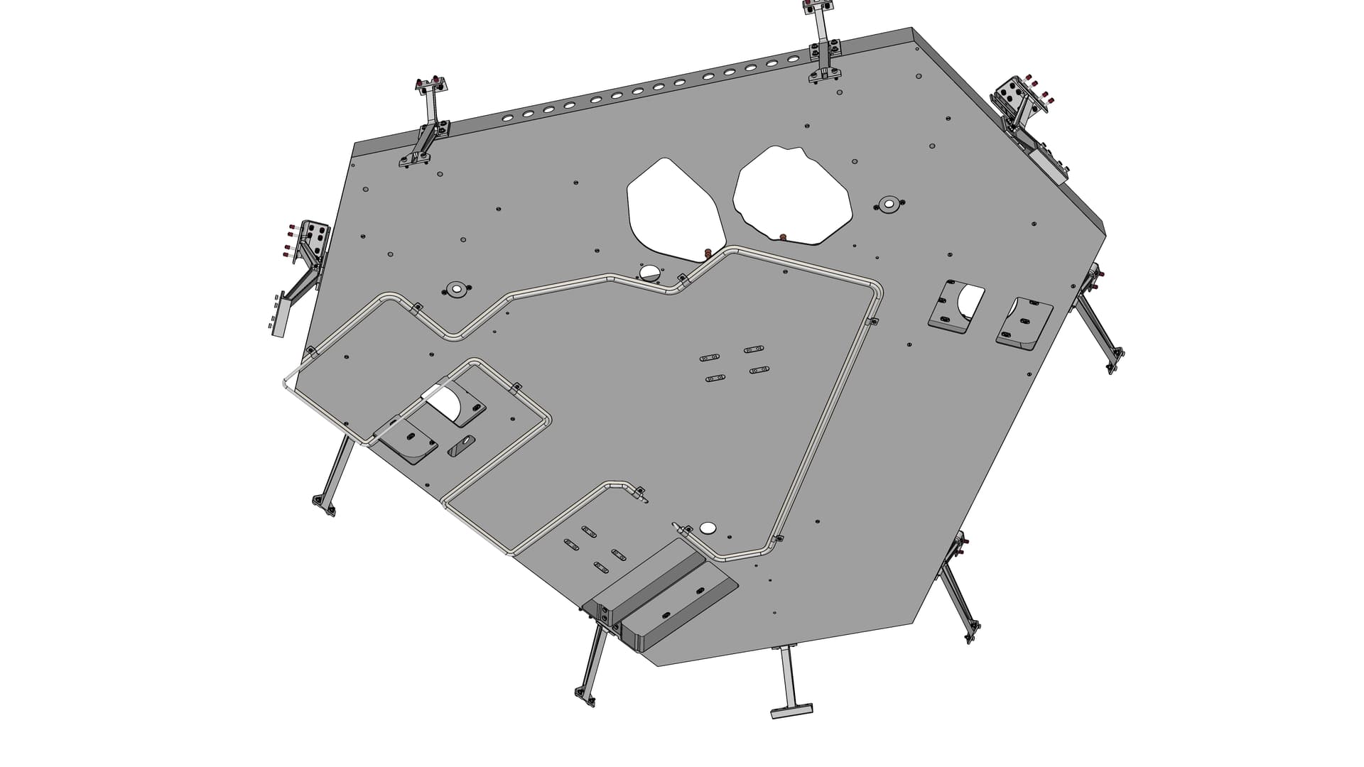
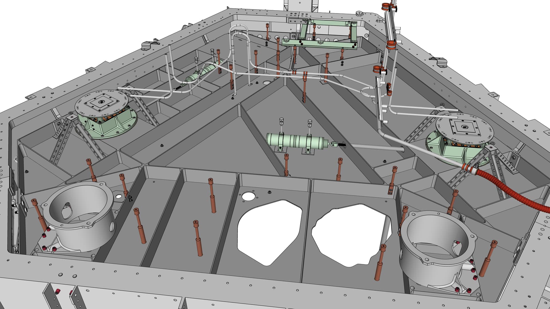
The Viking '75 Mars lander’s fuel system model is complete. Here are overall views of the work-in-progress lander (which is still missing many large external components) with the fuel tanks and all the lines and valves in place, along with the four roll-control thrusters that are mounted on the fuel tanks (two thrusters per tank). Front view:
Top view:
The next image is just the fuel system, without any other parts of the lander. There are about 300 unique Solid components in the fuel system: valves, lines, fittings, and roll-control thruster assemblies. The fuel lines (3/4 inch OD and 1/4 inch OD) were manufactured in sections, which were sometimes joined by welding and other times via couplings. The model represents each distinct section before welding or coupling.
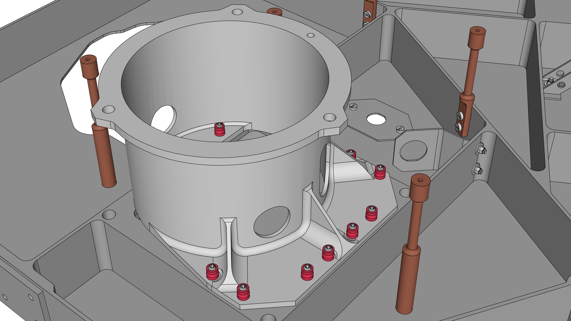
The four small fuel lines in a vertical cluster right of center are for filling the fuel tanks with hydrazine (N2H4) propellant, which was done after the final two-day heat sterilization of the entire sealed lander capsule. The two right-most lines of the cluster are for the lander’s two fuel tanks. The two left-most lines of the cluster are to fill two additional fuel tanks within the aeroshell capsule that protected the lander (not in the model). The aeroshell had 12 small rocket thrusters that were used to brake the capsule out of Mars orbit. The pair of aeroshell tank fill lines are routed horizontally through a couple of turns, then go nearly vertically down to dead-end near the bottom of lander fuel tank 1 on the right. At the dead-end point, a pyrotechnic tubing cutter on the aeroshell severed the lines before the aeroshell was jettisoned, about a minute before landing on Mars.
Here are comparisons between the SketchUp model and the test lander unit at the
Virginia Air and Space Science Center. This test unit differs in various ways from the actual Flight landers on Mars (and is missing some parts), but it was my primary reference (having taken many many dozens of photographs and measurements of it in 2014). Photographs of the Flight landers during build-up that show these details are extremely limited. Most historic photographs were taken after insulating blankets were installed that completely hide the tanks and nearby plumbing.
The two MR-50F roll-control thrusters (made by Rocket Research Company, now part of Aerojet Rocketdyne) mounted on each of the lander’s two fuel tanks were mentioned earlier. The
MR-50F SketchUp model is available by itself on the 3D Warehouse. Here is a view of the thruster pair on fuel tank 2:
The purpose of the roll-control thrusters was to control rotation or roll of the lander about its vertical axis during the final minute before landing on Mars. A pre-planned heading was chosen so that the final azimuth at landing would face in the desired direction for optimal mid-day solar illumination of the Mars surface for camera imaging during the landed mission. (This worked as planned for both Viking 1 and 2 when they landed in July and September 1976, respectively.)
The thruster’s gold cylinders are thin heat shields, to limit the heat radiated to the rest of the spacecraft from the thrust chamber within the shields. The black cylinder on the inboard end of each thruster are fuel valves. The light gray thruster nozzle is just barely visible protruding from the outboard end of the heat shield, pointing outward and slightly down (to cope with being off the lander’s vertical center of gravity).
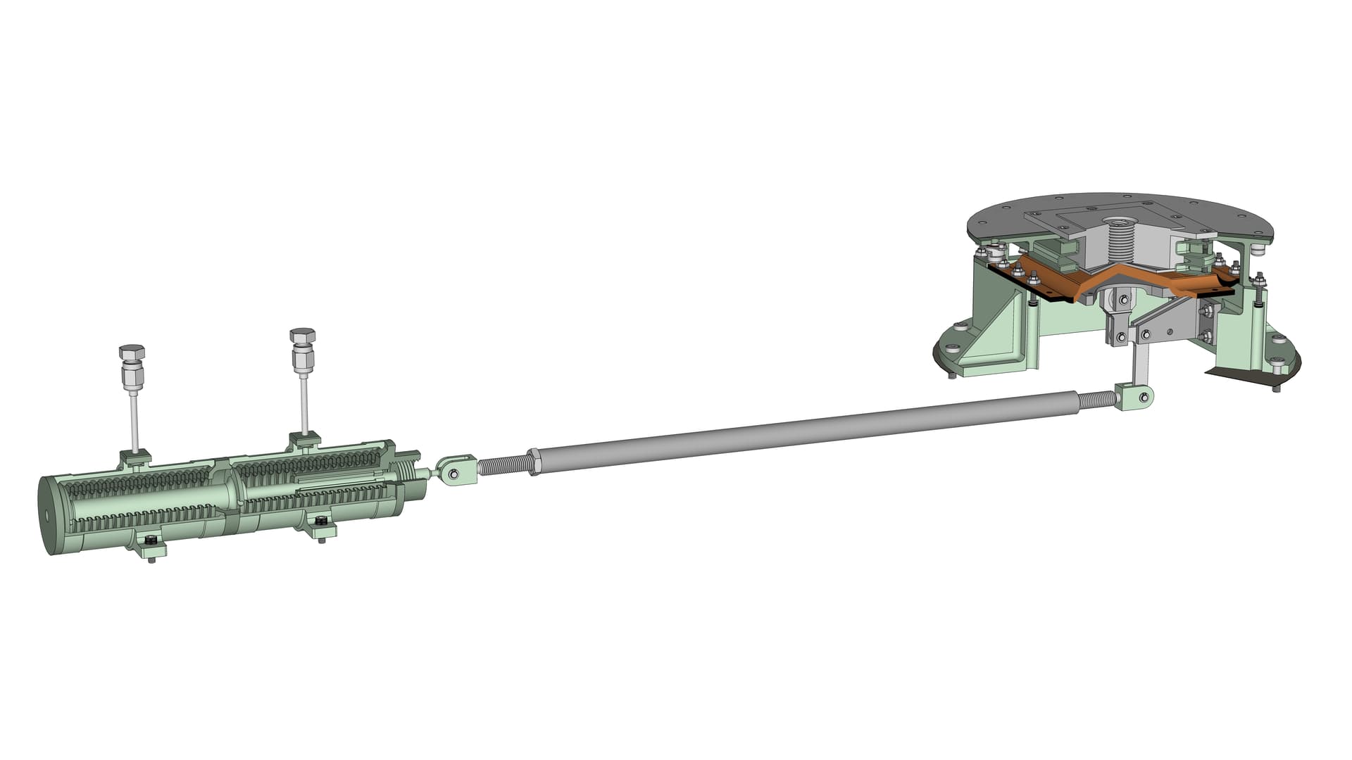
Here is an exploded view of a mounted thruster (which includes a one-piece machined aluminum mounting fitting at center, behind the thruster body):
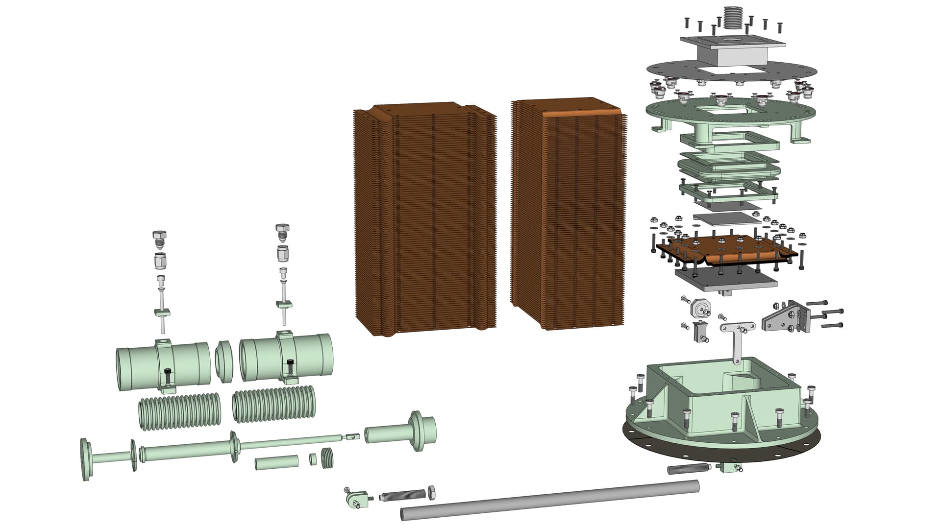
An exploded view of a thruster itself:
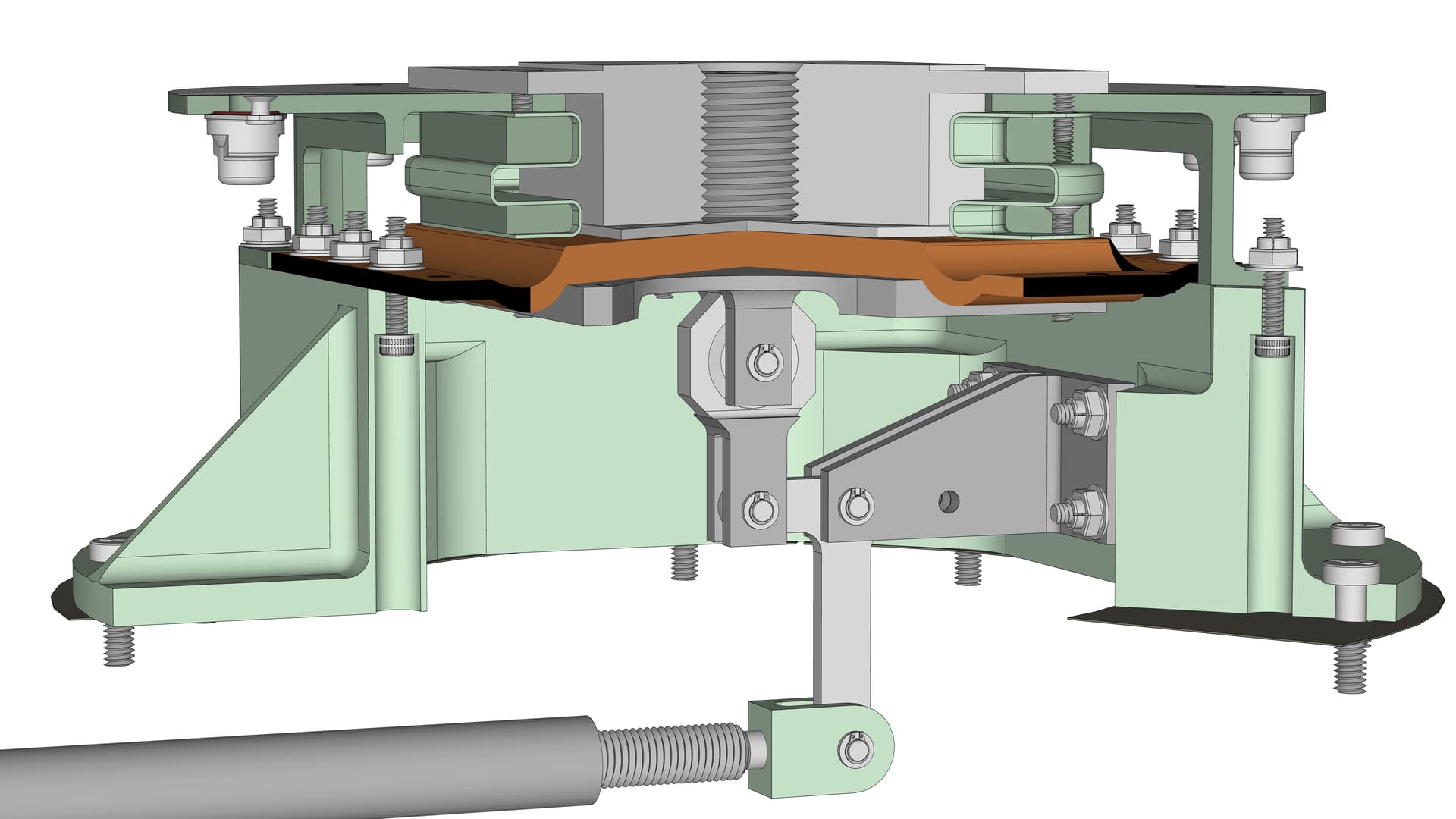
And a cut-away view of a thruster:
Hydrazine propellant was pressure-fed into the end of a dual solenoid valve (into a cavity in the upper-left corner of the above image). The dark striped ovoid forming the right side of the cavity is a fuel filter.
Two identical solenoid-actuated valves are in series. Two valves were included for redundancy. The biggest worry was a failed valve that stuck open, letting the thruster run continuously and forcing an opposed thruster to also fire continuously to counteract the torque. In addition to flight control complications, this would deplete fuel at a rate faster than anticipated. It was extremely unlikely that both of the dual valves would fail open. A failed-closed scenario was less of a concern, because the equivalent thruster on the other fuel tank could do the job (and fail-closed of both equivalent thrusters was also very unlikely).
The two solenoid electromagnet coils are the gold objects with lines representing the coiled wire. When electrically actuated they pulled an armature disc slightly toward the coil (to the left in the above image). The displaced armature compressed a small tapered coil spring at the center of each valve which opened a poppet mechanism (tiny white disc) to allow fuel to flow through the center of the valve, toward the right.
The pressure-fed fuel would then travel through the tiny straight channel connecting the valves to the thrust- or reaction-chamber just right-of-center, at the core of the thruster (within the gold heat shield). The feed channel is split into three tiny branches. The three branches lead to two stacked “Rigimesh” discs which further disperse the fuel before it reaches the upper catalyst bed - the thick light gray disc with a pebble texture. This volume of the thrust chamber was tightly packed with Shell 405 catalyst, which is granules of aluminum plated with iridium - the active catalyst ingredient. When hydrazine comes in contact with iridium, it immediately decomposes into nitrogen gas and hydrogen gas (producing a lot of heat in the process). This is how a monopropellant hydrazine engine works. there is no combustion, no need for a separate oxidizer (thus, “mono” or single-propellant).
Two additional larger Rigimesh screens separate the upper catalyst bed from the larger lower catalyst bed. The lower bed is packed with a smaller granule size (more surface area) to promote a more complete reaction of the remaining hydrazine that passed through the upper catalyst bed without reacting. Two final Rigimesh screens at the bottom of the lower catalyst bed, just before the narrow throat of the reaction chamber and expanding exhaust nozzle, retain the catalyst granules within the thruster. The catalyst is not consumed by the reaction; so long as hydrazine is fed into the chamber, the engine will continue producing thrust.
The hot nitrogen and hydrogen exhaust gasses finally exit the thruster via the expanding nozzle, producing 8 pounds of thrust (in the Viking configuration). This type of engine cannot be throttled, it is either off or on at full power. It can be pulsed in very short operations (milliseconds) for fine flight control.
Recently I was delighted to acquire an actual MR-50F thruster reaction-chamber-nozzle component. I spent a lot of time measuring the unit. The following image shows how I measured a stack of successive diameters of the nozzle exterior, using acrylic shims to control the vertical offset of the measurement plane. To measure the nozzle’s interior diameter I made a resin casting of it, and then used the same technique on the casting. I also made a casting of the chamber throat interior to determine its angle of convergence (which turns out to differ from a published figure) and the curves connecting the convergent and divergent (expanding) portions of the nozzle.
The overall work-in-progress Viking '75 Mars lander SketchUp model remains available on
DropBox via this link (warning, the file is ~260MB).