Yes, this kind of situation can be a rail pain in SketchUp. The intersection will look like a horrid zig-zag up close, but from a distance it will look better. The short edges that are created at the intersection may not withstand even the “Dave” method. When this happens to me, I manually fudge the adjacent endpoints and/or draw new edges (often including long diagonals on the connected faces) to repair the damage caused by SKetchUp’s validity-check “repair”.
If you want two curved surfaces to ‘match up’ as they intersect, then they must have the same number of segments and their spacings must also match. Otherwise the cut will be jagged…
Ok, here is how I did it. Hope this is an OK way to do it and I wont be having serious misalignment issues down the path when dealing with real materials.
In order to avoid having huge diagonals along the edge that is to be attached to the plywood part of the horn, I located profiles as close to each other as possible:

I then used the Cuviloft option that draws only intermediate edges:

I tried to draw a line along the long edge of the mitered profile so that I have a face on it which didn’t lead to any success.
So I accidentally tried Skin Contrours command and it made a face on this mitered profile with a lot of diagonals:
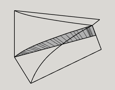
After that, i used Loft along path first vertically and than horizontally and now I have to parts with a miter:

Sides of these parts can be extruded of CNCed separately and after that glued to the rest of the model.
What do you think?
It is a pain that forum doesn’t allow me to put several pictures in one post.
Anyway, i was going to CNC the curved parts and parts of the joint. Do you think it is gonna be a pain for the carpenter to then put all the parts together?
Let’s return to the basic model. I tried to solve the curve problem in the following way.
I first copied the horizontal profile curve and moved it so that the points A coincide (see my previous post), then I scaled it in the direction of the x axes so that the points B also coincide.

The result does not satisfy me, because it can be seen that the surface of the straight part will not be tangent to the curve. It is easy to notice that the original curve is not very correct and a fracture of the curve is visible in the middle of it.
Now I tried to repeat the same with the vertical profile curve. The result in relation to the straight surface is already better, but I did not get a complete coincidence of curves here either (of course).

So my question is: how correct are the profile curves shown in the model, and how are they geometrically constructed? Are the curves based on a measurable geometric body (circle, ellipse, arch, etc.)?
Well, i am trying to replicate what was done in this thread on another forum. In the case of the author of that post, he left the horn standing on its own. Well, with the help of a post, so that it doesn’t fall down. In my case I’ll be putting it in a cabinet.
The geometry of the profile is called "modified tractrix’, as the original producer of the horn calls it. In the case of the thread i linked to, I don’t know how the author of that post derived that profile geometry. I doubt that he used formulas, it is more likely that he just drew it in Autocad.
I simply took the picture of the profile from that thread and tried to replicate it in Sketchup as closely as possible. I used 2 point arc tool to draw those profiles as i know no other way of doing it as of now ![]()
Seems to me you may be overthinking it, it might be that you just need to decide the profile you want and use follow me. You could then scale if necessary or adjust it in various ways, each quarter can be separated out as a group or component.

1 Like
That animation you posted, Box, almost made my head explode ![]()
Ok, will this method allow me to preserve the dimensions necessary for the horn? Acoustic properties may vary largely with little minor change applied to the profile.
Also, i want to make straight sided part out of plywood and curved part will be CNCed.
Anything is possible.

I’d recommend you spend some time learning the basic before you go any further.
https://learn.sketchup.com/
Constructing an unmodified tractrix between two points requires much more than just the name of the curve. You also need to know what and how is modified when it comes to a modified tractrix. Without this basic knowledge, any curve will only be approximate.
I agree with @Box that a sufficiently accurate representation can also be obtained with the Follow Me tool. Only I would not scale all the details, but only the curved parts of the profiles (upper and lower or right and left) as I showed in my previous post, otherwise the thickness of the materials will also scale.
If I understood you correctly, then the your existing horn geometry is rather rough and slight smoothing it will not cause any harm. I recommend using the Bezier Curve Tool from the Extension Warehouse for this purpose. You also have to learn to work with it. If you have taken into account all of the above, it will not be difficult for you to get accurate profiles that can be processed with CNC equipment.
If you still have questions, feel free to ask.
1 Like
Thank you guys, I will learn the tools you mentioned and will report back.
It was very helpful. Sorry for asking this kind of questions before driving deeper into basics.
вт, 5 янв. 2021 г., 16:57 Guntis Konstants via SketchUp Forum <sketchup@discoursemail.com>:
1 Like
So i got much more accurate copy of the profile using Bezier Curve Tool. Then i proceeded with Follow Me tool and it gave me a rectangular horn (well, the curved part of it):
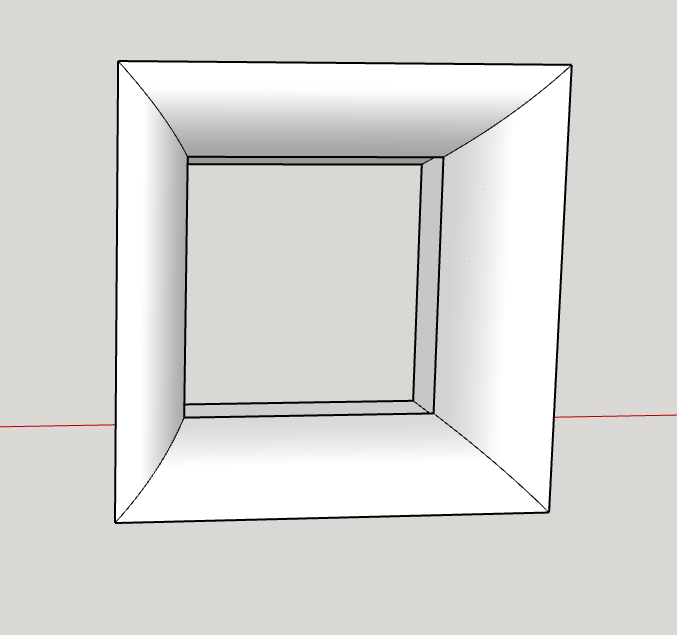
When i scale it to the needed width, the thickness of of the material also scales, as @kamambers warned:

How do I prevent this?
You could make the ‘path’ the correct shape, or select the geometry of a side and move it into place.
Scaling is perhaps the right thing to do, but I wonder if removing the outer shell and remodelling the material thickness with, for instance, Fredo’s JointPushPull would produce the correct shape.
This what I meant by make the path the right size, or move one quarter.
If you create the path the size you want and align the profile it will come out the right size and shape.
One created it is also just geometry, so it is possible to select just parts of it and move it to create the size you want.

Another option.
