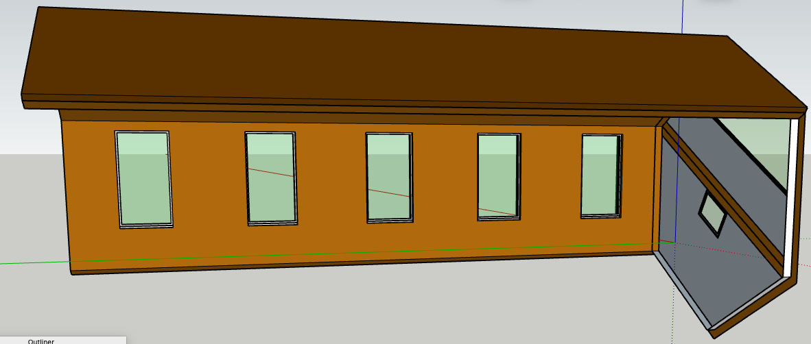
FlexTools problem: In the first attached set of 5 windows, you can see through the windows. In the second set, after the model had been rotated 60 degrees, the windows were no longer transparent.
Why? RH Hexagon Apr 22.skp (995.4 KB) RH Hexagon Apr 22 After Rotation.skp (989.9 KB)
I attached the before & after SKP files in case there was a change happened within the second one.
The interior wall group doesn’t have any holes in it so it’s no wonder you can’t see through the windows. It’s like the sheetrock hasn’t been cut around the windows.
What happened is the windows were, in my opinion, perfect. Then I rotated the entire hexagon 60 degrees. That changed the SKP file so that the windows are no longer transparent. (See the 2 attachments.)
I’ve turned hexagons 60 degrees several times. This is the first time it ever changed the opacity of the windows.
Not sure exactly what happened but the side windows are not components. They are faces and they are not grouped with anything. So it’s likely that you selected some or all of your groups/components and rotated them. That would not necessarily have selected the faces… unless you did a dragging selection that included them.
It does look like you are selecting everything in the video.
Are the two files the same?
It seems the side window glass is out of alignment in the rotated model.
The other model you shared can be rotated… I actually would have guessed you’d rotate from the center of the hexagon, not from the corner of the bounding box.
RH Hexagon Apr 22 copy 2.skp (1.0 MB)
Sorry Learned One. I had previously attached a SKP file. But, I should have attached another because there was a new video.
Your windows are all different. Rather than unscramble an egg, I’d redo the windows using only one window component.
But first I would create and save a template that has:
Length snapping disabled so it never causes problems again. It frequently causes small measurement errors (creates the " ~ " shown in measurements).
Profiles turned off so it is easier to see lines.
Always use this template as it will help to avoid errors! Especially watch for the tilde " ~ " in your measurements. It technically means, “approximate”. But in practice it often means, “incorrect”.
Looking at your ‘glass’, which is loose geometry but should be components: they are not all identical.
But also, your Flex Fixed Windows already have glass (in the sash group).
So you can get rid of your loose geometry glass.
Dave pointed out that you don’t have holes cut in the wall. Can’t say why… but you can turn the Flex Windows off and see there are some problems with the walls.
Here is one way you can use Move + Control (Options on Mac, I think) to copy some geometry to cut holes. You can see that after using Intersect Faces, the lines/edges are on the wall face so the interior face of the window can be cut out.
You’ll need to cut holes into the Right Perimeter AND Outer 4" walls. Cutting a hole in one will not cut a hole in the other.
[quote=“3DxJFD, post:12, topic:269549”]
You said, “your Flex Fixed Windows already have glass (in the sash group)”.
[/quote] I don’t see any evidence of windows. For instance, I cannot change the colour of the “window” with varying intensities of opacity.
Please explain how I can “paint” the windows with transparent glass.
Thank you for the information about “length snapping disabled” and “profiles turned off”. I made sure that was done before I made the SKP file I sent you today.
I’ve added your wisdom to my well-indexed file of SketchUp instructions.
I’m using the latest upload: RH Heagon Apr 23 3pm.
The glass is light blue and difficult to see. One way to quickly check if there is a transparent material on the glass is to switch to Monochrome. Since you can see through the window when materials are on, but not when they are not, there is a transparent material.
Here is how you could adjust the transparency:
I don’t know. I haven’t used the Wall Cutter tool. It sounds like you are correct that it would do that. But the proof is in the pudding and in the model you shared the holes were not there.
I would try to make it a habit that once I was done with drawing geometry to turn it into a component right away. Most of the time -but not always- loose geometry is going to cause trouble. You might forget about it and end up having it stick to new geometry you are adding for something else. For example, if you were going to draw a frame around the glass and the glass was not a component, your new frame would stick to it.
Those are two settings that can cause problems. The Length snapping one sometimes introduces small errors. Having the Profiles turned on makes it more difficult to see when a line is, or is not, on a face.
For example, in the pictures below, you can see the same edges but with profiles turned on some look different (bolder line weight).
With profiles off the lines are lighter… so if you see thick looking lines there may be a problem.
The architect I will be working with likes to have light green windows. Does anyone know how I can change those windows I’ve created so that they will have a green tint?
It looks like you put the transparent green glass material on the entire window component. That makes everything in the component (or group) take on that material. You just want it on faces inside of the component or group. In general, put the materials on faces, not groups or components.
You can see in the video that there is green glass on the entire window. So even though there is blue glass on the actual glass component you can’t see it.
Here I put the default material back onto the component. Then I open the glass (off screen) and put your green glass material on. Which was Material17. Probably easier to know which is which if you name the materials as you make them!
And “Yes” I broke the rule about putting materials on components. The reason I did that is because that’s what had the other blue glass material. My first guess is that Flex Tools can change the thickness and number of glass panes and it controls all of their materials by putting it on the containing component. But the general rule still applies to put materials on faces.
It looks like something else happened when you copied the windows: part of the wall hitched a ride. It’s the wall_all component in the some of the windows. Maybe that is from one of the tools. Since I don’t know I’m going to cut it out. Hopefully it isn’t needed.
Now you have a bunch of mismatched windows. The window I’ve been adjusting has the desired material glass material color and doesn’t have the wall_all so I’m going to use that for all of the lower windows.
The upper window glass: change material on glass then replace selected components to swap out the other 4. You can’t see Replace Selected because the menu is out of the recording area… but you use the right click on the component in the Component Tray to access it.
I can see that Flex Tools has some clever tagging going on… I don’t know if I’m breaking any of that. But I’d rename for clarity and purge the model of the other window components.