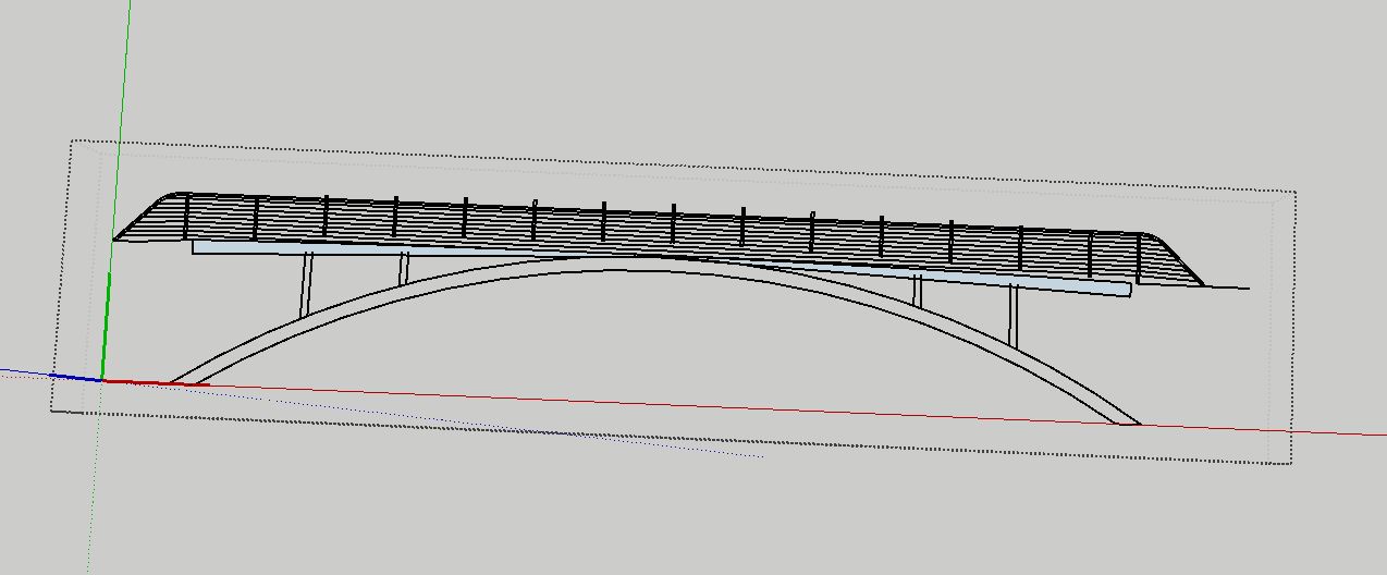
Hi, I am importing linework from CAD to SKP and I’m experiencing some weird glitch. The linework appears differently almost like it isn’t picking up what was trimmed or extended in CAD. All of this linework is flat and was imported in a separate file. This did not seem to make it right. Any advice on why this is occurring and ways to fix it? As you can see in SKP (white screen), the lines of the posts are extended past the rail and the places where the beams align at the bottom feel very off.

Is it imported at the right size? Can you share the .dwg file?
new bridge.dwg (478.1 KB)
CAD file is here above. I looked at my import options and nothing felt off to me but not sure. I tried to import into a fresh SKP but no avail.
How big is the thing supposed to be? What are the missing entities in the CAD program? Do you need to explode them?

Looks like both of those bottom beams are about 1’ while the overall length of the bridge is roughly 78’. This matches in the SKP file currently so no scaling seems to be occurring. It is purely linework (lines and polylines). I exploded it and it seemed to help with the top rail but now the top rail is reading as seperate lines and I can’t smooth the segments which is causing it to look sloppy and pointed. A lot of linework is still out of place for some reason. There is a little bit of overlap in the cad but it isn’t quite that extreme and I need the lines because the objects are not supposed to be coplanar.

Very odd. I imported with units sets to meters to try to make sure to avoid any tiny edges. There seem to be some oddities about the file, though. Notice how the verticals are displaced in my attempt. I can’t tell where the problem lies. Is it a problem with the .dwg file or what?

That said, I would tend to follow the general wisdom about imported CAD files and only use them as a reference for creating the proper model geometry. I would draw the geometry from scratch in SketchUp and use groups or components as I make the 3D model. As it is all of the geometry in the import is one lump which would make it tedious at best to work with.
DWG looks fine on home PC with Acad 2021. I did explode the polyline curves to arcs and it did import some what “better” but not great. Here it is in SU Pro 2021 and Form Z Free 9.

Here is the file saved as a dxf and in MoI…

The number of segments that SketchUp allocates to imported polyline arcs seems to be somewhat random. Here it seems that the long radius segments in the railings are imported as a edge.
I opened the file in Rhino and exploded the polylines. Then arcs imported as arcs, although many had only 2 segments, and most others had too few to look smooth. I then corrected some of the segment counts in Entity Info but not all.
bridge.skp (88.4 KB)