What I am trying to achieve is an adapter that has a 2 TPI left-hand thread with a diameter of 1.5". I am working in meters X10. It looks pretty in SketchUp but the slicer screws it up. I am using Curve Maker and Upright Extruder to make the profile. Solid inspector shows internal face edges. trying to clean this thing up is a chore, producing bat results. Where am I going wrong? Should I be drawing in inches X10 or what?
forum scene.skp (497.7 KB)
Is the profile correct? If so, let me see what I can do.
Is it supposed to be solid or a hole down the middle?
Here’s a quick copy done using truebend. Not perfectly accurate, I made a guess or two.
forum scenebox.skp (577.0 KB)
What does it look like in a slicer?
Do you mean does it show as a sliceable solid, yes. I didn’t make it a specific size tho if that’s what you mean? I could do.

That is what I am looking for, showing as a sliceable solid. I just finished dinner, BBQ Spares and a bottle of wine. This is fodder for tomorrow morning. I will let you know the results.
D
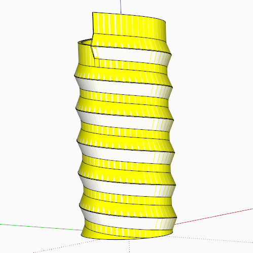
The outside looks OK, although it has a top and bottom face. How did you achieve the result?
The main issue with your model is all the junk inside the shape, I have no idea how you created all these internal faces.
I wasn’t clear you wanted it to be hollow and couldn’t tell exactly what you’re trying to achieve because of all the strange internal faces. I used the same method I used in the tutorial video I posted last year on drawing screw threads which I thought you were trying to follow. Once the thing is solid, though, putting a hole in it is trivial.
Just out of interest, I made these at the correct size no scaling or anything, 96s no holes. I know it’s not the profile you were using but it is 2tpi and 1.5 inch dia

1.5 thread.skp (2.3 MB)
1 Like
It is a solid prior to setting the planes at each end to achieve a height of 20M or 2". I am going to try Split to plane.
That is exactly what I have been working with.
The tiny faces show when flatting the ends to gain the height desired.
Something’s missing in your process.
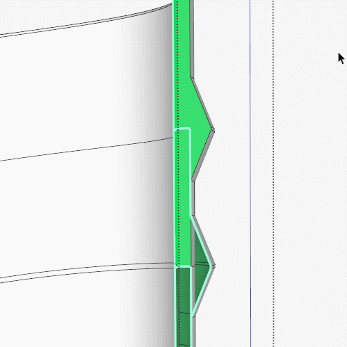
Is there supposed to be a hole down through the thing? If so, it would be easier to add it after you’ve created the solid screw. For some reason there’s also a problem with your starting profile which results in the smal edges Box shows in his section view.
OK, I will try a different approach and substitute the thread point with an arc. More later.
I changed the vertical height of the profile to get it working. Also, I ran CleanUp3 on it and ignored Solid Inspectors’ advice. Next, it was imported into the slicer, also ignoring the warnings. the print is what I need. Unfortunately, the pitch is unknown as I am copying an existing Shop-Vac fitting.
Thanks for the help.
Dave’s method works well and I’m honestly not sure what it is you are doing that is creating all those internal faces.
I personally like using Truebend to create threads and it can be very accurate. I’ve made a video, shock horror not a gif, of how I get the profile from your model and use it to make the thread with truebend.
I’m also not sure how you want the ends cut off, your model has an extension at the top which can be done by simply moving the top face up, but I have simply cut it at the point of the thread. I didn’t bother repeating the action for the bottom as it is the same.
Note I use Zorro2 to slice the model using the section plane. And Fixit 101 to remove the inner face. Both actions can be done manually.
I’ve set this video as unlisted as I’m trying to make it viewable to anyone in this thread but not public on my channel, let me know if it doesn’t work for anyone here.

3 Likes
Very informative. Even though I have achieved my goal, there are some good tips here I can use in the next part to be coupled to the profile I have made.