Face Orientation into 3rd Party App

I’m writing and importer to read skp files into another application. However I keep having problems with flipped normals. I’ve looked through the forum and seen the various answers provided. The models I’m using to test are those supplied with SketchUp and I’ve checked the orientation of the faces by selecting monochrome and looking for front and back faces. I’ve tried testing for the normals, checked loop, edge and edgeuse direction and still I get flipped faces. The bed.skp example ends up with one side, some corner faces and one end of the mattress flipped. I think I’ve captured all the transformations as overall the object looks correct apart from the face directions. I’ve even tried to use the mesh helper to triangulate the faces, this didn’t work either. Is there some way within SketchUp of find out which transformations have been applied to a face, component of group.

Thank you.

Via UI to visually inspect?

I got Transformation inspector:

https://extensions.sketchup.com/en/content/transformation-inspector

All though - you only get transformations for groups, component instances and images. Faced, Edges etc inherit from their parent containers.

In order to get the correct orientation it should be enough to collect the combined transformation of the parent containers of a face and use the vertex order of the face’s loop.

That’s the best I can suggest for such a generic question though. If you got specific code (that can be copy+pasted to run) and models it might help.

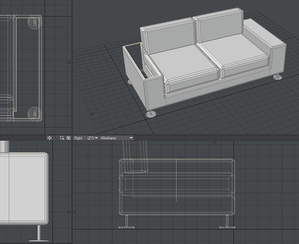
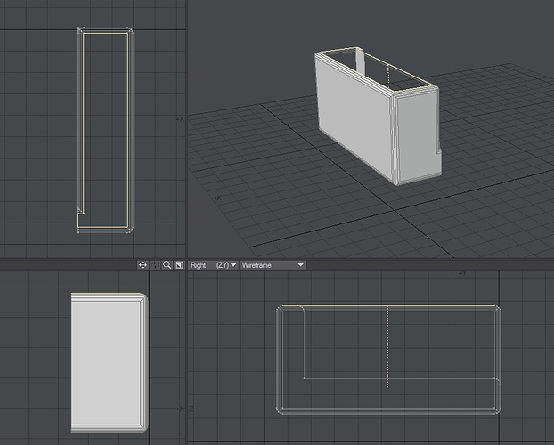
Thanks for the information on the extension. I’ve attached two images, one from Sketchup the other from Lightwave after importing. The highlighted faces have their normals pointing in the opposite direction to those in the sketchup image. I’ll see what the extension indicates. The model used is the bed.skp that is supplied with SketchUp 2016. As previously stated I’ve check the face orientation in Sketchup.

Thanks.

Perhaps you can share some code that shows how you read the faces? At the moment we don’t have much info to go by.

Sussed it out. By getting the determinant of the 4x4 matrix of the last transformation I can set the point order to CW or CCW.

1 Like

Flipped faces on import of skp model into lightwave. I’m using the couch.skp file that comes with 2016. I end up with one face flipped in the couch arm. On the other arm which is a transformed version of the arm I have no problems. I’ve been using the skp to xml project as a guide.

Is there a definitive way of getting the point order for the face. I’ve tried loops, edges and edgeuses to get winding orders and looked at the normal vector of the face.

If I use the mesh helper to create a tessellated object I can get all the faces pointing in the correct direction. However I don’t want to use triangles as this makes any further modelling laborious.

Attached is part of the function for writing the face and images of objects as they are imported into lightwave.

Any pointers would be appreciated.

Thanks

FacePoints.txt (3.8 KB)


Sometimes the issue comes from transformation applied to instances. This usually happens when you have a mirrored part for example. As you’ve already found, if the determinant of the transformation matrix is negative the transformation does flip the faces, so you should reverse the vertex sequence. Beware that only the rotation part of the matrix must be used (so make 0 the scale and translate factors of the matrix before calculating det)

Hi, my formulae for calculating the det value uses just those in the 3 x 3 matrix. I have managed to get faces orientated in the correct direction by recalculating the the face normals after import and that works for about 99% of the cases.

I’ve revised my face drawing function to use edges and edgeuses and depending on whether the edge is reversed I get either the first or last vertex from the edge. However I still have a problem with some of the faces being flipped. I use the bed.skp and couch.skp files that are supplied as test objects. Previous images show the couch arm with one face flipped. I can run a normalize routine on the faces however it can result in some correct faces being flipped incorrectly.

Am I missing some information from the SDK regarding transforming points, some function that I need to call?

Face_Draw.txt (4.7 KB)

I tried importing the bed.skp without any transformations and if I use the outerloop one end of the headboard is reversed, i.e. the normals point into the center of the headboard. If I try with the edges and edgeuses both outer ends of the the headboard point into the center of the headboard. So it would appear not to be the process of applying the transformations but how the points and being selected from either the outer loop or edge/edgeuses.

Is there some test that I can do on the face/edges to get the correct orientation?

Thanks.

Why does it do this? Because SketchUp doesn’t care about other programs working with SketchUp models. Most will draw with dual-sided surfaces anyways.

Where does this matter? When you use a program that ONLY draws the “normal”, which is faster to draw. (Games)

Also, it matters with double-sided face drawing, if the “surface smoothing” is calculated by the “normal-face orientation”. If every other triangle is “flipped”, it turns a flat surface into a chunk of lasagna noodles. Trying to “bend the surface”, at every other reversed “normal”. Creating inaccurate shades and bumps and “normal-maps”.

Face-normals are calculated by one of two methods, right-hand or left-hand. CW or CCW order of the “points”.

When an object is triangulated, the order of rotation is being lost. Programs usually have a “fix”, called “recalculate normals”, which attempts to “Face the surfaces”, in all one direction. If it guesses wrong, you then only have to reverse all normals, to get them the right way.

You have to do some 3D calculations, as the orientation is based of CW or CCW ordering in 3D space, not 2D space. The order is not always “lowest to highest”.

First, you have to figure-out the original surfaces orientation/normal. Then, using that CW or CCW order, you start to create a NEW set of shapes to replace the single surface that you are triangulating. You can actually “cheat” and use a fast-render to “test” the surfaces you are creating. (Using GL and a camera, you get the pixel-value of the scene with the original surface drawn in the center. Then, in a new camera, add the “test shape”, to the center of the screen, and get that pixel value. If the value is the same, it is correctly faced. If the pixel value is NOT equal, it is facing the wrong way from the original surface.)

I believe there is even a call for this, without the use of the camera. Drawing a “shape”, you can get the “normal value”, which is an XYZ orientation. One of the values will be negative, if the face flipped. Just try reordering the points, until you get the desired matching “normal” values.

Also note, the point order will also alter the UV mapping, if the points are not just reverse-ordered. It has to be exact reverse order. A-B-C → C-B-A.

Also note, Direct-X use opposite ordering from OpenGL. (Has to do with a copyright thing. Just as one uses left-top drawing for UV-Mapping, and the other uses bottom-right drawing for UV-Mapping.)